EP0349020A2 - Herstellung und Verpacken von Strümpfen - Google Patents
Herstellung und Verpacken von Strümpfen Download PDFInfo
- Publication number
- EP0349020A2 EP0349020A2 EP89116758A EP89116758A EP0349020A2 EP 0349020 A2 EP0349020 A2 EP 0349020A2 EP 89116758 A EP89116758 A EP 89116758A EP 89116758 A EP89116758 A EP 89116758A EP 0349020 A2 EP0349020 A2 EP 0349020A2
- Authority
- EP
- European Patent Office
- Prior art keywords
- hose
- former
- transfer
- support
- carrier
- Prior art date
- Legal status (The legal status is an assumption and is not a legal conclusion. Google has not performed a legal analysis and makes no representation as to the accuracy of the status listed.)
- Withdrawn
Links
- 238000004806 packaging method and process Methods 0.000 title claims description 29
- 238000004519 manufacturing process Methods 0.000 title description 4
- 230000007246 mechanism Effects 0.000 claims description 24
- 238000000034 method Methods 0.000 claims description 17
- 239000000969 carrier Substances 0.000 claims description 5
- 210000003371 toe Anatomy 0.000 abstract 2
- 239000010410 layer Substances 0.000 description 21
- 238000007689 inspection Methods 0.000 description 10
- 239000004744 fabric Substances 0.000 description 2
- 238000000926 separation method Methods 0.000 description 2
- 210000003423 ankle Anatomy 0.000 description 1
- 230000009286 beneficial effect Effects 0.000 description 1
- 238000003780 insertion Methods 0.000 description 1
- 230000037431 insertion Effects 0.000 description 1
- 238000009940 knitting Methods 0.000 description 1
- 239000002991 molded plastic Substances 0.000 description 1
- 238000009877 rendering Methods 0.000 description 1
- 230000000717 retained effect Effects 0.000 description 1
- 238000004826 seaming Methods 0.000 description 1
- 238000009958 sewing Methods 0.000 description 1
- 239000002356 single layer Substances 0.000 description 1
Images
Classifications
-
- B—PERFORMING OPERATIONS; TRANSPORTING
- B65—CONVEYING; PACKING; STORING; HANDLING THIN OR FILAMENTARY MATERIAL
- B65B—MACHINES, APPARATUS OR DEVICES FOR, OR METHODS OF, PACKAGING ARTICLES OR MATERIALS; UNPACKING
- B65B25/00—Packaging other articles presenting special problems
- B65B25/20—Packaging garments, e.g. socks, stockings, shirts
-
- B—PERFORMING OPERATIONS; TRANSPORTING
- B65—CONVEYING; PACKING; STORING; HANDLING THIN OR FILAMENTARY MATERIAL
- B65D—CONTAINERS FOR STORAGE OR TRANSPORT OF ARTICLES OR MATERIALS, e.g. BAGS, BARRELS, BOTTLES, BOXES, CANS, CARTONS, CRATES, DRUMS, JARS, TANKS, HOPPERS, FORWARDING CONTAINERS; ACCESSORIES, CLOSURES, OR FITTINGS THEREFOR; PACKAGING ELEMENTS; PACKAGES
- B65D85/00—Containers, packaging elements or packages, specially adapted for particular articles or materials
- B65D85/18—Containers, packaging elements or packages, specially adapted for particular articles or materials for wearing apparel, headwear or footwear
Definitions
- the present invention relates to improvements in hosiery manufacture and packaging; "hosiery” and “hose” mean leg garments of full length, knee-length or ankle length.
- this invention aims to devise a hosiery package and method of packaging which may avoid the need for formers individual to each hose of a pair of hose.
- a pair of hose packaged for sale wherein a first hose of the pair is stretched flat on and by a former inserted in that hose and a second hose is disposed inside the first hose, between one face of the former and a confronting layer of the first hose.
- the single former may be a card or like board stiff enough to keep the first hose stretched flat. It may be substantially as long as the first hose and may have a rounded end for engagement by the toe end thereof.
- the former could be folded or doubled to keep the size of the hosiery package within reasonable bounds, especially in the case of full hose or knee-length hose.
- the assembly may be wrapped inside a transparent wrapping if desired and/or the card could be folded in half and a band, e.g. of card, could be placed around the then-confronting toe and welt end of the card-supported first hose. Such a band could bear printed information helpful to the seller and/or purchaser.
- a band e.g. of card
- a method of packaging a pair of hose wherein a first hose of the pair is mounted, preferably right-side out, on a flat former so as to be streched laterally thereby, a layer of the first hose confronting one face of the former is separated from the said face to create an open space, into which the second hose of the pair is inserted, and thereafter the said layer of the first hose is permitted, or caused, to move toward the said face so as to entrap the second hose therebetween.
- the first hose Before the first hose is mounted on the former, it and its companion hose may be in an inside-out state.
- the first hose is everted to a right side out state, e.g. in the course of mounting it on the former and the second hose is everted and thereafter delivered into the said space created between the first hose and the former.
- the second hose is everted by a suction everter and is delivered pneumatically into the said space.
- Another object of the invention is to integrate the process with the operation of a hose processing machine. Accordingly, the two hose are supported internally by a pair of hose carriers of a hose processing machine, the former is moved into operative juxtaposition with one of the carriers which supports the first hose and the latter is transferred onto the former so as to be supported internally by the former, the second hose thereafter being dismounted from its carrier and inserted into the first hose between the latter and one face of the former.
- the former will be juxtaposed with the said one carrier such that former and carrier are aligned end-to-end, ends adjacent, and the first hose is stripped in a forward direction from the carrier across to the adjacent former and is drawn with eversion thereof onto the former.
- the said machine can, for instance, be a toe closer, an inspection machine or a boarding machine.
- the invention provides a method of finishing and packaging a pair of hose, starting with tubular hose blanks that are open at both their opposite ends, comprising closing toe ends of the two blanks, thereafter drawing a first of the toe-closed hose onto a flat former so as to be supported internally and stretched laterally thereby, preferably in a right side out state, creating a space between one of the layers of the first hose and one face of the former by separating the said one layer from the face, inserting the second toe-closed hose into the said space, and then permitting or causing the said one layer to move toward the said face of the forger to entrap the second hose inside the first hose, thereby forming a hose package assembly comprising the first hose supported flat by the inserted former with the second hole located to one side of the former and inside the first hose.
- the invention also seeks to provide apparatus for automatically providing a pair of hose packaged for sale. Accordingly, the present invention provides apparatus for packaging a pair of hose wherein one hose is stretched flat on a former and the other hose is located inside the first hose, comprising means to support the first hose in operative relationship to a flat former, means to transfer the first hose from the support means onto the former so as to closely encircle the former, means to separate one layer of the first hose temporarily from one face of the former, and means to deliver the second hose into the space created by the temporary separation of the said layer of the first hose from the former.
- the support means and former are disposed adjacent one another in general end-to-end alignment, and said transfer means is operative to load the first hose with eversion onto the former.
- said hose is mounted in a right-side out state on the former, even though it may have been inside-out on the support means.
- the transfer means is movable between the support means and the former and includes a hose-engaging element, the element being positioned and operable to engage a welt end of the first hose located on the support means, to remove the hose therefrom and to transfer the hose to the former and to mount it in an encircling position about the former.
- the apparatus includes means to hold the former in operative juxtaposition to the support means, and the transfer means is arranged to transfer the first hose onto both the former and the holding means so that the said hose encircles both.
- the holding means includes a hollow body configured to create the said space between the first hose and the former.
- the apparatus also includes means to grip an end of the former and the first hose, the gripping means and holding means being relatively movable to disengage the holding means from the encircling first hose such that the latter slips from the holding means and closely encircles the former.
- the support means can comprise inspection forms or boarding forms respectively of a hosiery inspection machine or hosiery boarding machine, or the leg supports or carriers of a toe closing machine.
- a preferred embodiment of the intention is a hosiery finishing and packaging machine comprising, in combination, a toe closer including two supports for a pair of hose to be toe closed, means to place a first of the supports and a flat packaging former in operative juxtaposition after toe closing of the first hose, the second support being adapted to evert the second hose by suction after toe closing thereof, a transfer mechanism and a conveying means, the transfer mechanism being operable to evert the first hose and place it in an encircling relationship on the former, the said mechanism being movable between the operatively-juxtaposed first support and the former and having a hose engaging element which is positioned and operative to engage a welt end of the first hose on the first support, to remove the first hose therefrom, to transfer it to the former and to mount it in an encircling position on the former, the conveying means being arranged to deliver the everted second hose into a space temporarily formed between the first hose and one face of the former.
- finishing and packaging machine is meant to produce a pair of hose packaged for sale, as hereinbefore defined.
- the apparatus can be configured, adapted or operated such that the hose are mounted on individual formers such as cards, if such is desired, instead of placing one hose in a space between one face of the former and a confronting layer of the other hose.
- Pairs of card mounted hose will then be gathered, mechanically or manually, for wrapping together to form a package.
- a pair of hose can be prepared for wrapping as a package by gathering one card-mounted hose and associating with it a second hose which is not mounted on a card; the second hose could, for instance, simply be laid upon the card-mounted companion of the pair.
- the invention also provides a hosiery finishing and packaging machine, such as a toe closer, having a suppoprt for a hose to be toe closed, means to place a flat packaging former in operative juxtaposition with the support for transfer of the hose from the support to the former, and a transfer mechanism operable to evert the hose and place it in an encircling relationship on the former, the transfer mechanism being movable between the operatively-juxtaposed toe closer support and the former and having a hose engaging element, the element being positioned and operative to engage a welt end of the hose located on the support, to remove the hose therefrom, to transfer the hose to the former and to mount it in an encircling position about the former, and means to deliver the former-mounted hose to another station for assembling it with another hose to make up a pair of hose.
- a hosiery finishing and packaging machine such as a toe closer, having a suppoprt for a hose to
- a method of packaging hose wherein a flat packaging former is juxtaposed with a hose mounted on a support of a hosiery processing machine, a transfer mechanism is operated to strip the hose from the support and mount it in a laterally-stretched condition encircling the former, and thereafter the hose mounted on the former is associated with another hose for packaging together as a pair.
- the other hose need not be, but could be, mounted likewise on a packaging former individual thereto.
- the other hose could be drawn over the first card-mounted hose such that the latter is contained within the other hose.
- a flat packaging former and a first hose mounted on a support of a hosiery processing machine are juxtaposed for a transfer of the hose to the former, a transfer mechanism is operated to strip the hose from the support and mount it in a laterally-stretched condition encircling the former, and thereafter the former bearing the said hose and another hose mounted on a support of the machine are juxtaposed and the or another transfer mechanism is operated to transfer the other hose and mount it in a laterally-stretched condition encircling the first hose and the former therein.
- the present invention is primarily concerned with finishing, and especially packaging, hose effectively in a manner suiting their inspection by prospective purchasers.
- a pair of hose is packaged using a relatively stiff backing former or card.
- the card is inserted in one of the hose and the companion hose is located between one surface of the card and a layer of the said one hose.
- the former is stiff enough to hold the said one hose flat and laterally stretched so that a layer thereof is clearly displayed for inspection.
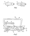
- Fig. 1 shows the pair of hose, the first hose 10 of the pair being stretched flat on and by the former 11 inside that hose.
- the second hose 12 is inside the first hose 10, between one face 13 of the former 11 and a confronting layer of the first hose 10.
- the former has a rounded end 16 for supporting a rounded toe T of the first hose 10, and is substantially as long as the first hose.
- the former can be shorter, longer or the same length as the first hose.
- the first hose 10 is mounted on the former such that its heel H confronts the face 13 of the former, the second hose being between this face and the lower or sole layer of the first hose. Since the first hose is stretched on and closely encircles the former, the second hose is securely retained within the first hose.
- the pair of hose and former can be enclosed in a transparent wrapping not shown and/or can be folded in half lengthwise and kept folded by the wrapping or by a band, not shown. Howsoever the hose are finally packaged, a top surface 18 of the first hose is displayed clearly against a backing comprising the confronting face of the former 11.
- the packaged hose shown in Fig. 1 could be assembled by placing the second hose 12 on the former 11 followed either by drawing the first hose 10 over them or by inserting them into the first hose.
- the method preferred, however, involves mounting the first hose 10 on the former 11 so as to be stretched laterally thereby, the lower layer thereof confronting the face 13 of the former is separated from the said face to create an open space therebetween, and the second hose 12 is inserted into this space. Thereafter the said layer of the first hose 10 is permitted, or caused, to move toward the said face 13 so as to entrap the second hose therebetween. Tension in the fabric of the laterally-stretched hose 10 pulls the said layer towards the face 13 of the former 11.
- the first hose 10 is everted to a right side out state, preferably in the course of mounting it on the former.
- the second hose 12 is everted and thereafter delivered into the said space created between the first hose 10 and face 13 of the former 11.
- the second hose is everted by a suction everter and delivered pneumatically into the said space.
- apparatus 20 comprises means 21 to support the first hose 10 in operative relationship to the flat former 11, means 22 to transfer the first hose from the support means 21 onto the former 11 so as to closely encircle the former, means 24 to separate one layer 25 of the first hose temporarily from one face 13 of the former, and means 26 to deliver the second hose 12 into the space created by the temporary separation of the said layer of the first hose from the former.
- the apparatus 20 also includes a second support means 28 for the second hose.
- Support means 21 and 28 are elongated members and are disposed adjacent and parallel to one another.
- the support means 21, 28 which support the hose 10, 12 internally are parts of a hosiery processing machine M.
- the machine could be an inspection or boarding machine, but preferably is a toe closer.
- the toe closer M can be of any type such as those manufactured and marketed by Detexomat Machinery Limited under the trade mark SPEEDOMATIC. See, for example, GB-B-1,501,869, GB-B-1,577,758 and GB 2,074,203. Full details of such toe closers are not given here since they are well known in the art, but a brief summary of such a toe closer follows.
- a plurality e.g. six, eight or ten hose support means, or leg carriers are mounted at intervals around a circular turret 30 which rotates upon a support 31 about a horizontal axis, the support means e.g. 21, 28 all projecting horizontally from a face of the turret.
- the support means move around an endless path in turn visiting several stations.
- a first station I visited by the support means is a loading station, whereat open-ended hose blanks are mounted inside oit manually or mechanically on the support means.
- the support means present toe ends of the hose blanks to a seamer such as a sewing machine.
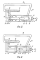
- the support means move to a discharge station III (shown in Figs. 2 to 7) whereat the toe closed hose are stripped from the toe closer and assembled with the former 11. After removal of the hose from their support means at station III, the said means move back to the loading station I for receiving new hose blanks for processing.
- the support means include suction tubes connectible through ports 36 in the turret 30 and support 31 to a source of suction.
- the tubes are exposed to suction at loading station I.
- Support means 28, but not 21, has its tube connected to suction at station III.
- the support means 21 is located in suitable alignment with means 35 which hold the former 11 and present it suitably to support means 21 for transfer of the first hose 10 to the former.
- the support means 28 has its hollow tube connected to aligned ports 36 in the turret 30 and its support 31 for suction to be generated in the tube at the appropriate time. Suction is used to strip the second hose 12 off support means 28 and evert it into its tube; after eversion, the second hose leaves the tube and enters conveying means 26 for pneumatic delivery into the first hose 10.
- the former holding means 35 comprise an elongated plate 39 and a hollow body 40 having an upper surface serving as the means 24 for separating the hose layer 25 from surface 13 of the former.
- the former 11 is inserted, or sandwiched, and gripped between the plate 39 and the hollow body.
- the holding means 35 comprising plate 39 and body 40 is movable towards and away from support means 21 at the discharge station. Suitable guide means 41 and drive means 42 are provided for controlling the movement of the holding means 35.
- support means 21 with a toe-closed hose 10 thereon arrives at station III, holding means 35 moves towards the support means 21. This is to dispose the support means 21 and former 11 adjacent one another in general end-to-end alignment, see Figs. 2 and 3. This movement brings the rounded end of the former 11 into engagement with the toe end of the hose 10 on the support means 21.
- a continued movement of the holding means 35 then causes the plate 39 and body 40 to slip along the now-arrested former 11 until corresponding ends of the plate 39 and body 40 are adjacent or in contact with the hose toe end. See Fig. 4.
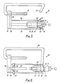
- control means renders the transfer means 22 operative to load the first hose 10 with eversion onto the former 11.
- the transfer means 22 is movable along guide means 44 by a drive means 45 and in this case includes two hose-engaging elements 46.
- the elements 46 are positioned and operable first to engage a welt end 48 of the first hose 10 located on the support means 21, then to remove the hose therefrom as the transfer means moves rightwards along the guide means 44.
- the transfer means 22 transfers the hose and mounts it in an encircling position about the holding means 35 and the former 11 held thereby. See Fig. 4 which illustrates an early stage in the operation of the transfer means, and Fig. 5 which shows the transfer means moved beyond and clear of the welt end of the hose now disposed about the holding means and the former.
- the operation of the transfer means 22 is such as to transfer the hose 10 with eversion from the support means 21 to the former which, at present, is located in the holding means 35. Due to tension in the fabric of hose 10 and the fact that it is stretched open as it is passed over the former 11 and the holding means 35, when the hose is released from the hose engaging elements 46 it closely encircles holding means 35.
- the hollow body 40 of holding means 35 has an upper surface 24 spaced clear of the top surface 13 of former 11.
- its layer 25 is spaced from the former suitably for receipt of the second hose 12.
- suction is generated in the suction tube of support means 28.
- the suction causes eversion of hose 12 into the suction tube.
- conveying means 26 is operated to convey the everted hose 12 pneumatically to the holding means 35.
- the conveying means 26 is a duct which is connected between the toe closer and the hollow body 40 of the holding means 35.
- the second hose 12 is then blown into the hollow body 40.
- the latter has an opening at its front end so that hose 12 can be blown to the toe end of the hose 10.
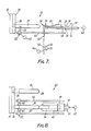
- the apparatus includes means 50 to grip an end of the former 11 and the first hose 10.
- the gripping means and holding means 35 are relatively movable to disengage the holding means 35 from the encircling first hose 10 such that the latter slips from around the holding means 35 and closely encircles the former 11.
- the gripping means 50 includes two jaws 51 mounted to a vertically movable stem 52 so as to adopt open or closed positions.
- the gripping means 50 is located below the path of movement of the holding means 35 except when the hose 10, 12 and former 11 are being disengaged from the holding means.
- the gripping means 50 is raised by a drive means 54, with the jaws open.
- the jaws 51 are level with the front of the holding means, they are closed to grip the toe of the first hose 10 and the rounded end of the former 11.
- the opening 56 at the front of the hollow body 40, and a suitable configuration or positioning of the plate 39, enable the jaws to grip the first hose and former.
- the holding means 35 is driven away from the gripping means 50 by drive means 42.
- the holding means is driven rightwards, i.e. away from the toe end of hose 10 and the rounded end of former 11.
- the first hose which encircled the holding means 35 slips therefrom and collapses around the former 11. Due to the width of the former relative to the girth of the first hose, the latter is laterally stretched on the former 11.
- the former and hose 10, 12 are disengaged fully from the holding means, whereupon the gripping means 50 can be lowered by drive means 54 and its jaws opened to release the packaged pair of hose.
- plate 39 of the holding means could be omitted, provided the hollow body 40 is furnished with means to hold the former 11.
- the equipment shown in Figs. 1 to 7 serves as a hosiery finishing and packaging machine comprising a toe closer including at least two supports 21, 28 for a pair of hose 10, 12 to be toe closed, means 35 which place a first 21 of the supports and a flat packaging former 11 in operative juxtaposition after toe closing of the first hose, while the second 28 of the supports is adapted to evert the second hose by suction after toe closing thereof.
- the machine includes a transfer mechanism 22 and a conveying means 26, the transfer mechanism 22 being operable to evert the first hose and place it in an encircling relationship about the former.
- the said mechanism is movable between the operatively-juxtaposed first support and the former and has a hose engaging means 46 positioned and operative (a) to engage a welt end 48 of the first hose 10 on the first support 21, (b) to remove the first hose from the support (c) to transfer it to the former and (d) to dispose it in an encircling position around the former 11.
- the conveying means 22 is arranged to deliver the everted second hose 12 into a space temporarily formed between the first hose 10 and one face 13 of the former 11.
- the apparatus disclosed hereinbefore is based on a toe closer having supports for the hose, but equally it could be based on an inspection machine or a boarding machine, or indeed on any hosiery processing machine having supports for hose which are suitable for coaction with a transfer mechanism.
- the hose 12 delivered pneumatically into the space inside hose 10 is derived from support 28 alongside support 21 on which hose 10 was previously mounted.
- support 28 could be part of a second hosiery processing machine which is operated in conjunction with a first hosiery processing machine that is fitted with the transfer mechanism 22, the former holding means 35 and the components allied therewith.
- Conveying means 26 will then extend from the second machine to the holding means 35.
- Such an arrangement may suit some hosiery manufacturers and may be a convenient way of achieving optimum prod uction rates.
- apparatus 20′ shown in Fig. 8 is the above-described apparatus adapted for this purpose. In essence, apparatus 20′ omits the facility to evert hose 12 and the pneumatic conveying means, or said facility and conveying means are disabled. In use of apparatus 20′, each support in turn is located in operative juxtaposition to the holding means 35 and a former held thereby. The hose on each support is then transferred to the holding means 35 and former 11, and the former 11 is thereafter disengaged from the holding means, all as described above. Once the first hose 10 is thus mounted on its former, the operation is repeated to place the second hose 12 on its former.
- the former-supported hose can be discharged and incorporated into packages with suitable wrappings.
- pairs of hose - each mounted on a former - can be assembled, manually or mechanically, and wrapped for easy inspection.
- a former-mounted hose can be associated with a companion hose to form a pair, the companion hose being in its limp, unmounted state.
- the companion hose may be simply laid on the former-mounted hose.
- the companion hose can be processed on the same machine as the hose that is mounted on the former, or on another machine in the hose manufactory.
- a package can readily be produced with the former-mounted hose presenting a single layer thereof to view for easy inspection by a customer.
- the companion hose could be drawn over the first, former-mounted hose so that both hose are in a laterally-stretched, flat condition encircling the one former.
- a former will be fed to and engaged with the holding means 35 for every other hose brought into juxtaposition with the holding means 35.
- the same transfer mechanism will, normally, be used for successively mounting the two hose of a pair on the former.
- the apparatus of Fig. 8 could be adapted, if desired, so as to place the second hose 12 in an encircling, mounted position about the first hose 10, after the latter has been mounted on the former 11.
- a transfer mechanism which e.g. is the same mechanism 22 employed for mounting the first hose 10 on the former 11, is then activated to transfer the second hose and mount it about the first hose 10 and the former 11 therein.
- the former 11 now bearing the successively mounted first and second hose 10, 12 is then disengaged from the holding means.
- a pair of hose, so mounted, can then be wrapped in a way permitting easy inspection of the nature and quality of the hose.
- the transfer means 22 could first strip the hose from support 21 in a forward or toe first direction as described. Then, the transfer means could move into operative juxtaposition with a former 11 disposed, for instance, generally alongside the support 21. The transfer means 22 could then be caused to make a return or rearward movement so as to don the hose welt first about the former.
- hosiery may be sold in units comprising more than a pair, e.g. in packages comprising two pairs.
- two pairs could be assembled using the apparatus 20 by adapting or rendering the apparatus operable to mount one hose 10 on a former and then to deliver three successive hose 12 into the space created temporarily between hose 10 and the former.
- each former-mounted hose obtained from apparatus 20′ can be associated a plurality of limp, unmounted companion hose, the latter e.g. being processed on other hosiery machines and delivered to an appropriate location for assembly with the mounted hose.
Landscapes
- Engineering & Computer Science (AREA)
- Mechanical Engineering (AREA)
- Auxiliary Devices For And Details Of Packaging Control (AREA)
- Treatment Of Fiber Materials (AREA)
Applications Claiming Priority (4)
| Application Number | Priority Date | Filing Date | Title |
|---|---|---|---|
| FR8610860A FR2601803B1 (fr) | 1986-07-21 | 1986-07-21 | Appareillage pour la mise en place d'un encart dans un bas ou une chaussette en vue de sa presentation |
| FR8610860 | 1986-07-21 | ||
| GB868621984A GB8621984D0 (en) | 1986-09-12 | 1986-09-12 | Hosiery |
| GB8621984 | 1986-09-12 |
Related Parent Applications (2)
| Application Number | Title | Priority Date | Filing Date |
|---|---|---|---|
| EP87306170A Division EP0254463B1 (de) | 1986-07-21 | 1987-07-13 | Herstellung und Verpacken von Strümpfen |
| EP87306170.9 Division | 1987-07-13 |
Publications (2)
| Publication Number | Publication Date |
|---|---|
| EP0349020A2 true EP0349020A2 (de) | 1990-01-03 |
| EP0349020A3 EP0349020A3 (de) | 1990-04-11 |
Family
ID=26225406
Family Applications (2)
| Application Number | Title | Priority Date | Filing Date |
|---|---|---|---|
| EP89116758A Withdrawn EP0349020A3 (de) | 1986-07-21 | 1987-07-13 | Herstellung und Verpacken von Strümpfen |
| EP87306170A Expired EP0254463B1 (de) | 1986-07-21 | 1987-07-13 | Herstellung und Verpacken von Strümpfen |
Family Applications After (1)
| Application Number | Title | Priority Date | Filing Date |
|---|---|---|---|
| EP87306170A Expired EP0254463B1 (de) | 1986-07-21 | 1987-07-13 | Herstellung und Verpacken von Strümpfen |
Country Status (3)
| Country | Link |
|---|---|
| US (2) | US4827693A (de) |
| EP (2) | EP0349020A3 (de) |
| DE (1) | DE3767399D1 (de) |
Cited By (1)
| Publication number | Priority date | Publication date | Assignee | Title |
|---|---|---|---|---|
| WO2002022719A1 (en) * | 2000-09-14 | 2002-03-21 | Toyo Tire & Rubber Co., Ltd. | Process for producing vulcanized rubber/thermoplastic resin composite |
Families Citing this family (9)
| Publication number | Priority date | Publication date | Assignee | Title |
|---|---|---|---|---|
| BR8807668A (pt) * | 1987-08-21 | 1990-06-05 | Pacific Dunlop Ltd | Processo e aparelho para dobrar bainhas de meia soquete |
| US5083414A (en) * | 1991-02-15 | 1992-01-28 | Wu Cheng M | Method for packaging birth control and disease preventing device |
| US5279094A (en) * | 1991-06-04 | 1994-01-18 | Bemis Company, Inc. | Apparatus for closing bags |
| US5136825A (en) * | 1991-08-28 | 1992-08-11 | Family Health International | Apparatus and method for compacting flexible, compactible articles |
| US5692606A (en) * | 1993-10-15 | 1997-12-02 | Elmaleh; Daphne | Compact hosiery packaging |
| USD490704S1 (en) | 2000-10-16 | 2004-06-01 | Daphne Elmaleh Zohar | Compact garment packaging |
| US6802418B2 (en) * | 2001-04-06 | 2004-10-12 | Daphne Elmaleh Zohar | Compact packaging for garments made from delicate materials |
| ITMI20011101A1 (it) * | 2001-05-24 | 2002-11-24 | Sergio Salvetti | Macchina per agevolare la disposizione di manufatti, in particolare calze,su forme di confezionamento e di esposizione |
| US10370131B2 (en) * | 2015-12-17 | 2019-08-06 | Victor Manuel Quinones | Apparatus and method for packaging coiled materials |
Family Cites Families (18)
| Publication number | Priority date | Publication date | Assignee | Title |
|---|---|---|---|---|
| US2481A (en) * | 1842-03-09 | Machine for gutting shingles | ||
| US622791A (en) * | 1899-04-11 | alexander | ||
| US622741A (en) * | 1899-04-11 | weller | ||
| US2870589A (en) * | 1954-12-06 | 1959-01-27 | John C Berry | Package forming machine |
| US2857085A (en) * | 1955-04-05 | 1958-10-21 | Wade V Bowman | Hosiery form inserting apparatus and method |
| US2896380A (en) * | 1956-03-16 | 1959-07-28 | Paramount Textile Mach Co | Method of and apparatus for forming hosiery package |
| US2989178A (en) * | 1956-10-24 | 1961-06-20 | Jr Edgar W Parker | Hosiery package, and method and apparatus for producing the same |
| US3099353A (en) * | 1956-11-09 | 1963-07-30 | Berry Brothers Corp | Stocking package and method |
| US2971302A (en) * | 1957-02-12 | 1961-02-14 | William J Berry | Stocking packaging machine and method |
| US3037770A (en) * | 1959-06-17 | 1962-06-05 | John S Palmer | Golf club |
| US3097770A (en) * | 1959-10-20 | 1963-07-16 | Alba Waldensian | Apparatus and method for packaging hosiery |
| GB955385A (en) * | 1962-05-15 | 1964-04-15 | Pasquale Agostino Gazzaniga | Apparatus for inspecting stockings and socks |
| US3209511A (en) * | 1962-11-28 | 1965-10-05 | Burlington Industries Inc | Method and apparatus for packaging stockings |
| US3486471A (en) * | 1966-03-31 | 1969-12-30 | Southern Textile Machinery Co | Method and apparatus for seaming and inspecting hosiery |
| US3826062A (en) * | 1973-05-10 | 1974-07-30 | Bear Brand Hosiery Co | Pneumatic package loader |
| DE3263051D1 (en) * | 1981-01-23 | 1985-05-23 | Detexomat Machinery Ltd | Boarding apparatus and method |
| EP0057056B1 (de) * | 1981-01-23 | 1985-04-10 | Detexomat Machinery Limited | Vorrichtung und Verfahren zur Abstreifen eines Strumpfes aus einem Behandlungsapparat |
| GB8303159D0 (en) * | 1983-02-04 | 1983-03-09 | Detexomat Machinery Ltd | Transferring hosiery between manufacturing machines |
-
1987
- 1987-07-13 DE DE8787306170T patent/DE3767399D1/de not_active Expired - Lifetime
- 1987-07-13 EP EP89116758A patent/EP0349020A3/de not_active Withdrawn
- 1987-07-13 EP EP87306170A patent/EP0254463B1/de not_active Expired
- 1987-07-14 US US07/073,018 patent/US4827693A/en not_active Expired - Fee Related
-
1989
- 1989-01-23 US US07/300,356 patent/US4972650A/en not_active Expired - Fee Related
Cited By (1)
| Publication number | Priority date | Publication date | Assignee | Title |
|---|---|---|---|---|
| WO2002022719A1 (en) * | 2000-09-14 | 2002-03-21 | Toyo Tire & Rubber Co., Ltd. | Process for producing vulcanized rubber/thermoplastic resin composite |
Also Published As
| Publication number | Publication date |
|---|---|
| EP0254463A1 (de) | 1988-01-27 |
| US4972650A (en) | 1990-11-27 |
| EP0349020A3 (de) | 1990-04-11 |
| DE3767399D1 (de) | 1991-02-21 |
| EP0254463B1 (de) | 1991-01-16 |
| US4827693A (en) | 1989-05-09 |
Similar Documents
| Publication | Publication Date | Title |
|---|---|---|
| US4972650A (en) | Hosiery manufacture and packaging | |
| JP2580088B2 (ja) | パンティストッキングの自動形成、製造装置及び形成方法 | |
| US4862815A (en) | Pantihose manufacture | |
| US4539924A (en) | Loading system for a toe closing assembly | |
| EP0184340B1 (de) | Vorrichtung und Verfahren zum Fördern von Strumpfwaren | |
| US3886026A (en) | Label applying apparatus | |
| JPH0999903A (ja) | 衣料品の袋詰め方法及び袋詰め装置 | |
| US4925022A (en) | Pantyhose package | |
| HU210246B (en) | Apparatus for cutting out sections of clotming articles from ribbon-like material, for example from web | |
| EP0057055B1 (de) | Einrichtung und Verfahren zur Behandlung von Strümpfen | |
| US5511501A (en) | Method and apparatus for handling flexible objects | |
| JP2000511855A (ja) | 更なる処理のために適切な配向で靴下ブランク又はパンティーストッキングを供給する装置及び方法 | |
| JPH03254762A (ja) | 使い捨てマスクの製造装置 | |
| US4602710A (en) | Loading system for a toe closing assembly | |
| US3902300A (en) | Flat folding and packaging apparatus and method | |
| US5024429A (en) | Method and apparatus for piling plural sheets of material having a repetitive pattern thereon, while ensuring the vertical alignment of the patterns from one sheet to the next | |
| US3470675A (en) | Packaging machine | |
| JPS62271826A (ja) | 靴下の折り畳み包装方法とその装置 | |
| WO1995027097A1 (en) | Method and apparatus for handling flexible objects | |
| US2842298A (en) | Hosiery boarding and form inserting apparatus | |
| US4712782A (en) | Method and apparatus of separating and transporting fabric pieces | |
| US4102727A (en) | Method for closing end portions of tubular fabric articles | |
| US3507234A (en) | Waistband end finishing apparatus and method | |
| US4323149A (en) | Transfer apparatus for natural tobacco leaves | |
| CN113574220B (zh) | 裤子处理装置及相应的裤架 |
Legal Events
| Date | Code | Title | Description |
|---|---|---|---|
| PUAI | Public reference made under article 153(3) epc to a published international application that has entered the european phase |
Free format text: ORIGINAL CODE: 0009012 |
|
| AC | Divisional application: reference to earlier application |
Ref document number: 254463 Country of ref document: EP |
|
| AK | Designated contracting states |
Kind code of ref document: A2 Designated state(s): DE ES FR GB IT |
|
| RIN1 | Information on inventor provided before grant (corrected) |
Inventor name: OLIVE, CORINNE Inventor name: EGEA, NOEL |
|
| PUAL | Search report despatched |
Free format text: ORIGINAL CODE: 0009013 |
|
| AK | Designated contracting states |
Kind code of ref document: A3 Designated state(s): DE ES FR GB IT |
|
| STAA | Information on the status of an ep patent application or granted ep patent |
Free format text: STATUS: THE APPLICATION IS DEEMED TO BE WITHDRAWN |
|
| 18D | Application deemed to be withdrawn |
Effective date: 19901012 |