EP0348949A2 - Plattensteuergerät - Google Patents
Plattensteuergerät Download PDFInfo
- Publication number
- EP0348949A2 EP0348949A2 EP89111788A EP89111788A EP0348949A2 EP 0348949 A2 EP0348949 A2 EP 0348949A2 EP 89111788 A EP89111788 A EP 89111788A EP 89111788 A EP89111788 A EP 89111788A EP 0348949 A2 EP0348949 A2 EP 0348949A2
- Authority
- EP
- European Patent Office
- Prior art keywords
- disc
- head
- memory
- track position
- track
- Prior art date
- Legal status (The legal status is an assumption and is not a legal conclusion. Google has not performed a legal analysis and makes no representation as to the accuracy of the status listed.)
- Withdrawn
Links
Images
Classifications
-
- G—PHYSICS
- G11—INFORMATION STORAGE
- G11B—INFORMATION STORAGE BASED ON RELATIVE MOVEMENT BETWEEN RECORD CARRIER AND TRANSDUCER
- G11B21/00—Head arrangements not specific to the method of recording or reproducing
- G11B21/02—Driving or moving of heads
- G11B21/08—Track changing or selecting during transducing operation
- G11B21/081—Access to indexed tracks or parts of continuous track
- G11B21/083—Access to indexed tracks or parts of continuous track on discs
-
- G—PHYSICS
- G11—INFORMATION STORAGE
- G11B—INFORMATION STORAGE BASED ON RELATIVE MOVEMENT BETWEEN RECORD CARRIER AND TRANSDUCER
- G11B7/00—Recording or reproducing by optical means, e.g. recording using a thermal beam of optical radiation by modifying optical properties or the physical structure, reproducing using an optical beam at lower power by sensing optical properties; Record carriers therefor
- G11B7/08—Disposition or mounting of heads or light sources relatively to record carriers
- G11B7/085—Disposition or mounting of heads or light sources relatively to record carriers with provision for moving the light beam into, or out of, its operative position or across tracks, otherwise than during the transducing operation, e.g. for adjustment or preliminary positioning or track change or selection
- G11B7/08505—Methods for track change, selection or preliminary positioning by moving the head
- G11B7/08517—Methods for track change, selection or preliminary positioning by moving the head with tracking pull-in only
Definitions
- the invention relates to a disc control apparatus, and more particularly to a disc control apparatus for controlling a reading and/or recording head to access to a disc having a spiral track.
- a conventional disc control apparatus for controlling a reading and/or recording head (simply called “head” hereinafter) to access to a disc having a spiral track
- the head is controlled to move from a first track(physical) position presently traced on the spiral track to a second track(physical) position to be next traced on the spiral track.
- the number of tracks is calculated between the first track position and the second track position, so that the head is moved in an inner or outer radial direction on the disc by a distance determined based on the calculated track number.
- Operation of moving the head on the disc from the first track position to the second track position at a predetermined high speed is defined as "seek", and a time period which it takes the head to begin reading information stored in the second track position of the disc stably after the head arrives on the second track position is defined as "settling time”.
- a rotating number of a disc having a spiral track used as, for instance, a CD-ROM is 360 rpm, and a moving speed of a head is 3 msec/one track, and further assumed that information is read from the center portion of the disc to the peripheral portion thereof under a state that the disc is rotated such that a track speed is linearly maintained constant relative to the head.
- the head is controlled to move from a first track position A of a spiral track to a second track position B of the spiral track which is on the outside relative to the first track position A by the track number of 5
- the head is started to move in a direction from the first track position A to the outer peripheral portion of the disc, and is stopped to move when the number of tracks is counted by "5", so that the head is assumed to arrive on the second track position B. Accordingly, information is read from the first track position A of the disc and then the second track position B of the disc successively.
- the conventional disc control apparatus there is a disadvantage that an access time becomes long for the following reason. That is, the disc is kept rotating during the moving of the head in the radial direction on the disc, thereby resulting that the head is positioned to be deviated from the second track position B which is a destination of the head by a distance determined based on a product of a moving time of the head and a rotating speed of the disc. As a result, operation of correcting the deviated position error in which the head is corrected to move from the deviated position to the destination (the second track position B) is necessary to be carried out.
- the rotating number N R1 of the disc is calculated during a time period of moving the head from the first track position A to second track position B in the equation (1).
- the rotating number N R2 of the disc is calculated during a settling time in the equation (2), where the settling time is 1.5 msec.
- the disc is rotated by approximately one before the head is stopped to read information from the disc.
- the head is inevitably moved to a third position C approximately corresponding to a track which is on the outside of the second track position B by one track number, unless the operation of correcting the deviated position error is carried out.
- a disc control apparatus comprises, a head for reading information from a disc having a spiral track, a first means for storing first data indicating a first track position on the spiral track of the disc which is presently traced by the head, a second means for storing second data indicating a second track position on the spiral track of the disc which is next to be traced by the head, a first memory for storing a first rotating number of the disc at a time period during which the head is moved under a seek operation, a second memory for storing a second rotating number of the disc at a settling time period, and an address means for producing address signals in accordance with the first and second data to access the first and second memories, a calculating means for producing a head moving signal in accordance with the first and second data, and the first and second rotating numbers, and a control circuit for controlling the head to move from the first track position to the second track position in accordance with the head moving signal.
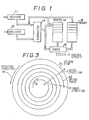
- a disc control apparatus in a first embodiment according to the invention.
- the disc control apparatus comprises registers 11 and 12, a subtracter 13, memories 14 and 15, and an adder 16, wherein an output of the register 11 is connected to a first input of the subtracter 13 and address inputs of the memories 14 and 15, an output of the register 12 is connected to a second input of the subtracter 13, an output of the subtracter 13 is connected to the address input of the memory 14 and a first input of the adder 16, an output of the memory 14 is connected to a second input of the adder 16, and an output of the memoriy 15 is connected to a third input of the adder 16.
- An output of the adder 16 is connected to a control circuit (not shown).
- the register 11 holds data of a first track position on a disc which is presently traced by a head
- the register 12 holds data of a second track position on the disc which is to be next sought by the head.
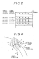
- the memory 14 is a read only memory (ROM) for storing a rotating number of the disc during a time period of a seek operation, wherein an address is determined by a combination of data (upper address) stored in the register 11 and those (lower address) of the subtracter 13 as shown in Fig.2, and the memory 15 is a ROM for storing a rotating number of the disc during a settling time which is calculated beforehand.
- ROM read only memory
- Fig.3 shows the disc 21 which is used for a CD-ROM having a spiral track 22, wherein the disc 21 is rotated in an anti-clockwise direction M, and the spiral track 22 is provided with address numbers increasing in a direction indicated by an arrow N.
- Fig.4 shows an enlarged portion of the disc 21 on which track positions A, B and C are indicated.
- the first track position A is "0010101 B "
- the second track position B is "0011010 B "
- the suffix "B” indicates that the codes are binary data, and a value of the data is plus (positive) when the most significant bit is "0", and minus (negative) when the most significant bit is “1”.
- These data are held in the registers 11 and 12, respectively, so that the subtraction "0010101 B -0011010 B " is carried out in the subtracter 13 to supply an output signal "1111011 B ".
- the memory 14 is accessed at an address including "0010101 B " (upper address) and "1111011 B " (lower address) to provide information of a disc rotation number under a seek operation.
- a content "0000001 B” of the memory 14 is supplied to the second input of the adder 16.
- the memory 15 is accessed at an address determined by the data of the register 11, so that a rotating number of the disc during a settling time is supplied from the memory 15 to the third input of the adder 16.
- the output data of the memory 15 is "0000000 B ". Therefore, the respective three output data "1111011 B “, "0000001 B “ and “0000000 B “ of the subtracter 13, and the memories 14 and 15 are added in the adder 16 to provide an added value "1111100 B " which is supplied to the control circuit.
- the control circuit controls the head to seek in an inner radial direction of the disc 21, as shown in Fig.3 and 4 by an arrow X, when the most significant bit of the added value is "0", and in an outer radial direction of the disc 21, as shown therein by an arrow Y, when the most significant bit is "1".
- the added value is "1111100 B ", so that the head is controlled to traverse (jump over) four tracks by seeking in the outer radial direction Y on the disc 21, and thus, the head is moved to the second track position B in a single seek operation.
- the head is moved to the third track position C as explained before in conjunction with the equations (1) to (3), despite that the head is controlled to move from the first track position A to the second track position B. Therefore, the head must be corrected to move from the third track position C to the second track position B. This is the aforementioned disadvantage of the conventional disc control apparatus.
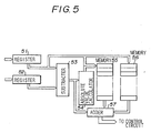
- Fig.5 shows a disc control apparatus in a second embodiment according to the invention.
- the disc control apparatus comprises registers 51 and 52, a subtracter 53, an absolute value calculator 54, memories 55 and 56, and an adder 57, wherein an output of the register 51 is connected to a first input of the subtracter 53 and address inputs of the memories 55 and 56, an output of the register 52 is connected to a second input of the subtracter 53, an output of the subtracter 53 is connected to an input of the absolute value calculator 54 and a first input of the adder 57, and output of the absolute value calculator 54 is connected to the address input of the memory 55, outputs of the memories 55 and 56 are connected to second and third inputs of the adder 57, and an output of the adder 57 is connected to a control circuit (not shown).
- the register 51 holds data for indicating a first track position presently traced
- the register 52 holds data for indicating a second track position to be next traced
- the subtracter 53 provides data for indicating a distance across which a head moves on a disc.
- the memory 55 is a ROM for storing a calculated rotating number of the disc at the time of a seek operation
- a memory 56 is a ROM for storing a calculated rotating number of the disc at a settling time.
- the data of the registers 51 and 52 are supplied to the subtracter 53, from which a subtraction value corresponding to a moving distance of the head is supplied to the absolute value calculator 54.
- an absolute value of the subtraction value is produced in the absolute value calculator 54, so that the memory 55 is accessed at an address determined by the data of the register 51 and the absolute value to provide the rotating number of the disc at the time of a seek operation.
- the memory 56 is accessed at an address determined solely by the data of the register 51 to provide the rotating number of the disc at the settling time.
- output data of the subtracter 53, and the memories 55 and 56 are added in the adder 57 to provide an added signal which is supplied to the control circuit. Consequently, the head is controlled to move in an inner or outer direction of the disc dependent on a content of the most significant bit of the added signal by jumping across a predetermined number of tracks determined by a content of the added signal excluding the most significant bit.
- the absolute value calculator is further provided as compared to the first embodiment. Therefore, the number of addresses is decreased in a memory for storing a rotating number of a disc to reduce a capacity thereof by a half, because the rotating numbers are equal in both inner and outer moving directions of a head.
Landscapes
- Moving Of Head For Track Selection And Changing (AREA)
Applications Claiming Priority (2)
| Application Number | Priority Date | Filing Date | Title |
|---|---|---|---|
| JP63161466A JPH0210580A (ja) | 1988-06-28 | 1988-06-28 | ディスク制御装置 |
| JP161466/88 | 1988-06-28 |
Publications (2)
| Publication Number | Publication Date |
|---|---|
| EP0348949A2 true EP0348949A2 (de) | 1990-01-03 |
| EP0348949A3 EP0348949A3 (de) | 1991-09-11 |
Family
ID=15735633
Family Applications (1)
| Application Number | Title | Priority Date | Filing Date |
|---|---|---|---|
| EP19890111788 Withdrawn EP0348949A3 (de) | 1988-06-28 | 1989-06-28 | Plattensteuergerät |
Country Status (3)
| Country | Link |
|---|---|
| US (1) | US5089999A (de) |
| EP (1) | EP0348949A3 (de) |
| JP (1) | JPH0210580A (de) |
Cited By (5)
| Publication number | Priority date | Publication date | Assignee | Title |
|---|---|---|---|---|
| EP0399513A1 (de) * | 1989-05-24 | 1990-11-28 | Sony Corporation | Verfahren zur Erfassung von Pitmustern |
| EP0463820A3 (en) * | 1990-06-29 | 1992-04-15 | International Business Machines Corporation | Disk drive apparatus and a seek method for spiral tracks |
| WO1992014248A1 (de) * | 1991-02-09 | 1992-08-20 | Deutsche Thomson-Brandt Gmbh | Verfahren zur verkürzung der zugriffszeit |
| EP1587080A1 (de) * | 2004-04-14 | 2005-10-19 | Deutsche Thomson-Brandt Gmbh | Spursprungsteuerungsverfahren |
| EP1587081A3 (de) * | 2004-04-14 | 2008-10-29 | Thomson Licensing | Spursprungsteuerungsverfahren |
Families Citing this family (8)
| Publication number | Priority date | Publication date | Assignee | Title |
|---|---|---|---|---|
| US5202864A (en) * | 1988-04-14 | 1993-04-13 | Matsushita Electric Industrial Co., Ltd. | Slip-off preventing tracking control apparatus |
| JP2702260B2 (ja) * | 1990-05-17 | 1998-01-21 | キヤノン株式会社 | 情報記録再生方法 |
| US5220545A (en) * | 1990-07-30 | 1993-06-15 | Nec Corporation | Disk controller including format control unit instructing directly jump back operation |
| JP2896925B2 (ja) * | 1990-09-04 | 1999-05-31 | 三菱電機株式会社 | 光ディスク記録装置 |
| US5315572A (en) * | 1991-01-23 | 1994-05-24 | Olympus Optical Co., Ltd. | Information reproducing apparatus capable of eliminating jitters |
| US6426843B1 (en) | 1999-04-27 | 2002-07-30 | International Business Machines Corporation | Settle time estimator feedback for rotational position reordering in data storage devices |
| KR100352816B1 (ko) * | 2000-03-10 | 2002-09-16 | 광주과학기술원 | 초고속 광검출기용 에피택시얼 구조 |
| TW200705398A (en) * | 2005-07-27 | 2007-02-01 | Lite On It Corp | Method for generating driving force parameter |
Family Cites Families (7)
| Publication number | Priority date | Publication date | Assignee | Title |
|---|---|---|---|---|
| JPS5753879A (en) * | 1980-09-12 | 1982-03-31 | Victor Co Of Japan Ltd | High-speed searching system for reproducer of disk-shaped information recording medium |
| JPH0812743B2 (ja) * | 1983-06-30 | 1996-02-07 | 株式会社東芝 | ディスク装置 |
| US4884259A (en) * | 1984-08-28 | 1989-11-28 | Fuji Photo Film Co., Ltd. | Optical memory disk and track access therefor |
| US4809094A (en) * | 1986-06-11 | 1989-02-28 | Matsushita Electric Industrial Co., Ltd | Method of accessing data recorded on a disk at a high speed |
| KR910005644B1 (ko) * | 1986-09-19 | 1991-08-01 | 가부시키가이샤 도시바 | 디스크재생장치 |
| JP2612262B2 (ja) * | 1986-12-16 | 1997-05-21 | 富士通株式会社 | 磁気デイスク装置 |
| US4839877A (en) * | 1987-10-02 | 1989-06-13 | International Business Machines Corporation | Rotational position controls for optical disk players using removable disks |
-
1988
- 1988-06-28 JP JP63161466A patent/JPH0210580A/ja active Pending
-
1989
- 1989-06-27 US US07/371,931 patent/US5089999A/en not_active Expired - Fee Related
- 1989-06-28 EP EP19890111788 patent/EP0348949A3/de not_active Withdrawn
Cited By (8)
| Publication number | Priority date | Publication date | Assignee | Title |
|---|---|---|---|---|
| EP0399513A1 (de) * | 1989-05-24 | 1990-11-28 | Sony Corporation | Verfahren zur Erfassung von Pitmustern |
| US5136564A (en) * | 1989-05-24 | 1992-08-04 | Sony Corporation | Pit pattern detecting apparatus and method |
| EP0463820A3 (en) * | 1990-06-29 | 1992-04-15 | International Business Machines Corporation | Disk drive apparatus and a seek method for spiral tracks |
| WO1992014248A1 (de) * | 1991-02-09 | 1992-08-20 | Deutsche Thomson-Brandt Gmbh | Verfahren zur verkürzung der zugriffszeit |
| EP0499323A3 (en) * | 1991-02-09 | 1992-12-16 | Deutsche Thomson-Brandt Gmbh | Method for reducing access time |
| TR25805A (tr) * | 1991-02-09 | 1993-09-01 | Thomson Brandt Gmbh | BIR KAYDETME VE/VEYA PLEYBEK TERTIBATINDA DÖNEN BIR DISK üZERINDEKI BIR DATA IZININ BELIRLI BIR HEDEF NOKTASINA GIRIS MüDDETINI KISALTMAK ICIN BIR USUL |
| EP1587080A1 (de) * | 2004-04-14 | 2005-10-19 | Deutsche Thomson-Brandt Gmbh | Spursprungsteuerungsverfahren |
| EP1587081A3 (de) * | 2004-04-14 | 2008-10-29 | Thomson Licensing | Spursprungsteuerungsverfahren |
Also Published As
| Publication number | Publication date |
|---|---|
| US5089999A (en) | 1992-02-18 |
| EP0348949A3 (de) | 1991-09-11 |
| JPH0210580A (ja) | 1990-01-16 |
Similar Documents
| Publication | Publication Date | Title |
|---|---|---|
| US5089999A (en) | Disc control apparatus | |
| US4723223A (en) | Direct memory access controller for reducing access time to transfer information from a disk | |
| EP0605222A1 (de) | Wiedergabegerät und Signalverarbeitungskreis für Daten, die auf eine Platte aufgezeichnet sind | |
| US4845571A (en) | Programmed reproduction system for still picture recording/reproduction device | |
| US5235576A (en) | Optical disc apparatus | |
| US4894732A (en) | Programmed reproduction system for still picture recording/reproduction device | |
| US5245594A (en) | Data read/write system for a disc storage unit | |
| US4907107A (en) | Method for positioning a magnetic head in accordance with digital peak values corresponding to servo data and magnetic disk positioning apparatus for the same | |
| US4763123A (en) | Signal selecting circuit for simultaneously performing plural input-output operations | |
| US5483389A (en) | Reproducing apparatus for temporarily writing reproducing data into memory | |
| US5146374A (en) | Method and apparatus for determining track position of a head on a recording medium | |
| US5574704A (en) | Header searching method and apparatus in a data recording medium | |
| US5164867A (en) | Magnetic disk storage and a method for accessing a track in a magnetic disk storage | |
| EP0285800A2 (de) | Servomechanismus für optischen Plattenspieler | |
| US4450552A (en) | Linear velocity control means | |
| JPH02282981A (ja) | トラッキングサーボ装置 | |
| US5953292A (en) | Rapid data reproduction method and apparatus for optical disk | |
| JPS61115126A (ja) | 磁気デイスク装置 | |
| JP2981449B2 (ja) | 情報記録再生装置 | |
| KR900006675B1 (ko) | 광 디스크 장치에서의 픽업 이송제어회로 | |
| JP2928689B2 (ja) | 光学ディスク再生装置 | |
| JPH01223677A (ja) | 磁気デイスク装置 | |
| JPH01155579A (ja) | ディスク装置のヘッド位置制御回路 | |
| JPH043374A (ja) | ディスク記憶装置のヘッド位置制御方式 | |
| JPS61264508A (ja) | 磁気デイスク装置 |
Legal Events
| Date | Code | Title | Description |
|---|---|---|---|
| PUAI | Public reference made under article 153(3) epc to a published international application that has entered the european phase |
Free format text: ORIGINAL CODE: 0009012 |
|
| 17P | Request for examination filed |
Effective date: 19890628 |
|
| AK | Designated contracting states |
Kind code of ref document: A2 Designated state(s): DE FR GB |
|
| PUAL | Search report despatched |
Free format text: ORIGINAL CODE: 0009013 |
|
| AK | Designated contracting states |
Kind code of ref document: A3 Designated state(s): DE FR GB |
|
| 17Q | First examination report despatched |
Effective date: 19921016 |
|
| STAA | Information on the status of an ep patent application or granted ep patent |
Free format text: STATUS: THE APPLICATION IS DEEMED TO BE WITHDRAWN |
|
| 18D | Application deemed to be withdrawn |
Effective date: 19930227 |