EP0348939A2 - Procédé pour orienter un dispositif optique à cristal liquide et appareil pour l'utilisation de ce procédé - Google Patents
Procédé pour orienter un dispositif optique à cristal liquide et appareil pour l'utilisation de ce procédé Download PDFInfo
- Publication number
- EP0348939A2 EP0348939A2 EP89111770A EP89111770A EP0348939A2 EP 0348939 A2 EP0348939 A2 EP 0348939A2 EP 89111770 A EP89111770 A EP 89111770A EP 89111770 A EP89111770 A EP 89111770A EP 0348939 A2 EP0348939 A2 EP 0348939A2
- Authority
- EP
- European Patent Office
- Prior art keywords
- liquid crystal
- optical device
- roll
- crystal optical
- orientation
- Prior art date
- Legal status (The legal status is an assumption and is not a legal conclusion. Google has not performed a legal analysis and makes no representation as to the accuracy of the status listed.)
- Granted
Links
Images


Classifications
-
- G—PHYSICS
- G02—OPTICS
- G02F—OPTICAL DEVICES OR ARRANGEMENTS FOR THE CONTROL OF LIGHT BY MODIFICATION OF THE OPTICAL PROPERTIES OF THE MEDIA OF THE ELEMENTS INVOLVED THEREIN; NON-LINEAR OPTICS; FREQUENCY-CHANGING OF LIGHT; OPTICAL LOGIC ELEMENTS; OPTICAL ANALOGUE/DIGITAL CONVERTERS
- G02F1/00—Devices or arrangements for the control of the intensity, colour, phase, polarisation or direction of light arriving from an independent light source, e.g. switching, gating or modulating; Non-linear optics
- G02F1/01—Devices or arrangements for the control of the intensity, colour, phase, polarisation or direction of light arriving from an independent light source, e.g. switching, gating or modulating; Non-linear optics for the control of the intensity, phase, polarisation or colour
- G02F1/13—Devices or arrangements for the control of the intensity, colour, phase, polarisation or direction of light arriving from an independent light source, e.g. switching, gating or modulating; Non-linear optics for the control of the intensity, phase, polarisation or colour based on liquid crystals, e.g. single liquid crystal display cells
- G02F1/133—Constructional arrangements; Operation of liquid crystal cells; Circuit arrangements
- G02F1/1333—Constructional arrangements; Manufacturing methods
- G02F1/1337—Surface-induced orientation of the liquid crystal molecules, e.g. by alignment layers
-
- B—PERFORMING OPERATIONS; TRANSPORTING
- B29—WORKING OF PLASTICS; WORKING OF SUBSTANCES IN A PLASTIC STATE IN GENERAL
- B29C—SHAPING OR JOINING OF PLASTICS; SHAPING OF MATERIAL IN A PLASTIC STATE, NOT OTHERWISE PROVIDED FOR; AFTER-TREATMENT OF THE SHAPED PRODUCTS, e.g. REPAIRING
- B29C55/00—Shaping by stretching, e.g. drawing through a die; Apparatus therefor
-
- G—PHYSICS
- G02—OPTICS
- G02F—OPTICAL DEVICES OR ARRANGEMENTS FOR THE CONTROL OF LIGHT BY MODIFICATION OF THE OPTICAL PROPERTIES OF THE MEDIA OF THE ELEMENTS INVOLVED THEREIN; NON-LINEAR OPTICS; FREQUENCY-CHANGING OF LIGHT; OPTICAL LOGIC ELEMENTS; OPTICAL ANALOGUE/DIGITAL CONVERTERS
- G02F1/00—Devices or arrangements for the control of the intensity, colour, phase, polarisation or direction of light arriving from an independent light source, e.g. switching, gating or modulating; Non-linear optics
- G02F1/01—Devices or arrangements for the control of the intensity, colour, phase, polarisation or direction of light arriving from an independent light source, e.g. switching, gating or modulating; Non-linear optics for the control of the intensity, phase, polarisation or colour
- G02F1/13—Devices or arrangements for the control of the intensity, colour, phase, polarisation or direction of light arriving from an independent light source, e.g. switching, gating or modulating; Non-linear optics for the control of the intensity, phase, polarisation or colour based on liquid crystals, e.g. single liquid crystal display cells
- G02F1/133—Constructional arrangements; Operation of liquid crystal cells; Circuit arrangements
- G02F1/1333—Constructional arrangements; Manufacturing methods
- G02F1/133365—Cells in which the active layer comprises a liquid crystalline polymer
-
- B—PERFORMING OPERATIONS; TRANSPORTING
- B29—WORKING OF PLASTICS; WORKING OF SUBSTANCES IN A PLASTIC STATE IN GENERAL
- B29K—INDEXING SCHEME ASSOCIATED WITH SUBCLASSES B29B, B29C OR B29D, RELATING TO MOULDING MATERIALS OR TO MATERIALS FOR MOULDS, REINFORCEMENTS, FILLERS OR PREFORMED PARTS, e.g. INSERTS
- B29K2105/00—Condition, form or state of moulded material or of the material to be shaped
- B29K2105/0079—Liquid crystals
-
- C—CHEMISTRY; METALLURGY
- C09—DYES; PAINTS; POLISHES; NATURAL RESINS; ADHESIVES; COMPOSITIONS NOT OTHERWISE PROVIDED FOR; APPLICATIONS OF MATERIALS NOT OTHERWISE PROVIDED FOR
- C09K—MATERIALS FOR MISCELLANEOUS APPLICATIONS, NOT PROVIDED FOR ELSEWHERE
- C09K2323/00—Functional layers of liquid crystal optical display excluding electroactive liquid crystal layer characterised by chemical composition
-
- G—PHYSICS
- G02—OPTICS
- G02F—OPTICAL DEVICES OR ARRANGEMENTS FOR THE CONTROL OF LIGHT BY MODIFICATION OF THE OPTICAL PROPERTIES OF THE MEDIA OF THE ELEMENTS INVOLVED THEREIN; NON-LINEAR OPTICS; FREQUENCY-CHANGING OF LIGHT; OPTICAL LOGIC ELEMENTS; OPTICAL ANALOGUE/DIGITAL CONVERTERS
- G02F1/00—Devices or arrangements for the control of the intensity, colour, phase, polarisation or direction of light arriving from an independent light source, e.g. switching, gating or modulating; Non-linear optics
- G02F1/01—Devices or arrangements for the control of the intensity, colour, phase, polarisation or direction of light arriving from an independent light source, e.g. switching, gating or modulating; Non-linear optics for the control of the intensity, phase, polarisation or colour
- G02F1/13—Devices or arrangements for the control of the intensity, colour, phase, polarisation or direction of light arriving from an independent light source, e.g. switching, gating or modulating; Non-linear optics for the control of the intensity, phase, polarisation or colour based on liquid crystals, e.g. single liquid crystal display cells
- G02F1/137—Devices or arrangements for the control of the intensity, colour, phase, polarisation or direction of light arriving from an independent light source, e.g. switching, gating or modulating; Non-linear optics for the control of the intensity, phase, polarisation or colour based on liquid crystals, e.g. single liquid crystal display cells characterised by the electro-optical or magneto-optical effect, e.g. field-induced phase transition, orientation effect, guest-host interaction or dynamic scattering
- G02F1/139—Devices or arrangements for the control of the intensity, colour, phase, polarisation or direction of light arriving from an independent light source, e.g. switching, gating or modulating; Non-linear optics for the control of the intensity, phase, polarisation or colour based on liquid crystals, e.g. single liquid crystal display cells characterised by the electro-optical or magneto-optical effect, e.g. field-induced phase transition, orientation effect, guest-host interaction or dynamic scattering based on orientation effects in which the liquid crystal remains transparent
- G02F1/141—Devices or arrangements for the control of the intensity, colour, phase, polarisation or direction of light arriving from an independent light source, e.g. switching, gating or modulating; Non-linear optics for the control of the intensity, phase, polarisation or colour based on liquid crystals, e.g. single liquid crystal display cells characterised by the electro-optical or magneto-optical effect, e.g. field-induced phase transition, orientation effect, guest-host interaction or dynamic scattering based on orientation effects in which the liquid crystal remains transparent using ferroelectric liquid crystals
Definitions
- the present invention relates to a method of orienting a liquid crystal optical device and to an apparatus usable for the method.
- the present invention relates to a method of orienting a liquid crystal optical device which can be advantageously employed as a practical method of orienting a liquid crystal material in the production of a liquid crystal optical device whereby providing a liquid crystal optical device comprising a highly oriented smectic liquid crystal and being suitable as a liquid crystal display device, a liquid crystal memory device or the like.
- the present invention relates to an apparatus which can be suitably used for the method of orienting a liquid crystal optical device.
- liquid crystal optical devices produced by employing a ferroelectric liquid crystal among smectic liquid crystals as a liquid crystal material, precisely controlling the orientation of the ferroelectric liquid crystal, and supporting the liquid crystal material between two substrates carrying their respective electrode layers have been attracting interest because of their excellent qualities, for example, high-speed response to external factors, such as an electric field, and high contrast ratio, and accordingly, their use for liquid crystal display devices, liquid crystal memory devices, etc. has extensively increased.
- the orientation control has been conducted by using a rubbing technique, a shearing technique, a temperature gradient technique, a sio oblique evaporation technique or the like.
- the orientation control using these techniques has deficiencies such as complicated pretreatment of substrates and complicated control operations. Further, the usual use of glass substrates causes problems such as difficulty in continuous production because of the troublesome conveyance process, difficulty in enlargement of area, etc.
- the orientation of liquid crystal molecules is induced by an orientation layer, such as a polyimide or polyvinylalcohol, which has been oriented by a rubbing treatment after having been provided on the surface of a glass substrate for supporting liquid crystal.
- an orientation layer such as a polyimide or polyvinylalcohol
- the above method (2) has problems in that
- An object of the present invention is to provide a practically advantageous method of orienting liquid crystal optical devices, which excels in that the method can realize very easy, high speed, and continuous production of a high quality of liquid crystal optical devices having excellent fundamental properties of liquid crystal devices, such as high contrast ratio and high speed of response to external factors including electrical field, and also having sufficient flexibility and easiness in enlargement of area, and which excels, as well, in that the method makes it possible to attain easily a high degree of orientation without subjecting substrates to any particular pretreatment for orientation control.
- Another object of the present invention is to provide a method of orienting liquid crystal optical devices and an orientation apparatus therefor which can produce liquid crystal optical devices having a high contrast independent of the anisotropy of substrates.
- Another object of the present invention is to provide a method of orienting liquid crystal optical devices and an orientation apparatus therefor which can use polarizing plates most efficiently, the polarizing plates being to be used as a component in liquid crystal optical devices.
- Another object of the present invention is to provide a method of orienting liquid crystal optical devices and an orientation apparatus therefor which have practical advantages in that continuous operation, particularly, orienting cut-sheet type and lengthy panel type of liquid crystal optical devices can be efficiently practiced. Further, due to its simple instrumental components and construction, the apparatus of the present invention can provide liquid crystal optical devices excelling in quantitative productivity and stability.
- Another object of the present invention is to provide an apparatus for orienting liquid crystal optical devices which is simple in construction, makes it possible to orient liquid crystal optical devices in an efficient, continuous operation by subjecting a lengthy liquid crystal optical element alone to bending treatment, and enables steady and a high degree of orientation.
- the inventors continued researches to achieve the above objects and found that, without particular pretreatment of substrates, highly oriented liquid crystal optical devices, such as liquid crystal display devices, having excellent high-speed responsibility and high contrast ratio can be easily obtained by an extremely simple procedure, i.e. by applying bending treatment to a liquid crystal optical device which comprises a smectic liquid crystal supported between two flexible substrates bearing electrodes, and that the procedure is particularly effective for liquid crystal optical devices produced by applying continuously and at a high speed a liquid crystal material consisting of a smectic liquid crystal, on a plastic substrate bearing electrode and subsequently, putting on the liquid crystal layer an opposite plastic substrate bearing electrode and then laminating at a high speed.
- the inventors consequently completed the present invention.
- the present invention provides a method of orienting a liquid crystal optical device including a smectic liquid crystal and two flexible substrates which support the smectic liquid crsytal layer between them and carry on their surfaces facing each other their respective electrode layers, which method comprises orienting the smectic liquid crystal by subjecting the liquid crystal optical device to a bending treatment.
- a polymer liquid crystal As the smectic liquid crystal, producibility of a film from the liquid crystal is extremely improved and plastic substrates can be suitably used, whereby enlargement in area becomes easy and productivity is increased. Further, the use of a polymer liquid crystal has the advantage that a high degree of orientation can be attained by a simple procedure without using rubbing technique, temperature gradient technique, sio oblique evaporation technique, or the like, which require complicated pretreatment.
- the present invention provides a method of orienting a liquid crystal optical device including a smectic liquid crystal, and two flexible substrates which support the smectic liquid crystal layer between them, and carry on their surfaces facing each other their respective electrode layers, which method comprises orienting the smectic liquid crystal by supporting the liquid crystal optical device with a supporting means consisting of at least one supporting sheet and subjecting the supporting means supporting the liquid crystal optical device to a bending treatment in the course of continuous move of the supporting means.
- the present invention further provides an apparatus for orienting a liquid crystal optical device comprising two supporting belts for supporting a liquid crystal optical device between them, at least two heating rolls for heating the liquid crystal optical device supported between the two supporting belts, a driving means for driving the two supporting belts, and at least one support roll for supporting jointly with at least one of the heating rolls the liquid crystal optical device supported between the two supporting belts.
- the present invention further provides an apparatus for orienting a liquid crystal optical device comprising a supply roll for supplying a lengthy liquid crystal optical device, at least one heating roll whose roll surface comes into contact with the supplied lengthy liquid crystal optical device in the course of the move of the lengthy liquid crystal optical device so that the lengthy liquid crystal optical device is heated and subjected to a bending treatment by the heating roll, and a winding roll for winding the lengthy liquid crystal optical device subjected to the bending treatment.
- the flexible substrates to be used in the present invention may be of various kinds. From the standpoints of productivity, wide use, processability, etc., however, it is preferable to use those made of a plastic or the like, which excels in strength, heat resistance, transparency, and durability.
- the flexible plastics include crystalline polymers such as uniaxially oriented or biaxially oriented polyethyleneterephthalate, noncrystalline polymers such as polysulfones and polyethersulfones, polyolefins such as polyethylene and polypropylene, polycarbonates and polyamides such as nylons.
- uniaxially oriented polyethyleneterephthalate polyethersulfones
- polycarbonates particularly preferred are uniaxially oriented polyethyleneterephthalate, polyethersulfones, and polycarbonates.
- the two substrates may be made of the same material, or each substrate may be made of a material different from that of the other.
- at least one of the two substrates is optically transparent and is provided with a transparent electrode layer.
- substrates to be used in the present invention there is no particular restriction in the form of the substrates to be used in the present invention, and the forms of the substrate to be used may vary depending on the purpose of use, etc.
- substrates of plate-form, sheet-form or film-form are preferably used in the present invention, and it is particularly preferable to use film-form substrates to take advantage of their fitness to continuous production system.
- the thickness of the substrates may be selected according to the qualities of the substrates such as the degrees of transparency, flexibility, strength, and processability, the purpose of use of the produced devices, etc., and it is generally from about 20 to about 1000 ⁇ m.
- the electrode structures to be used in the present invention may be of common kinds, for example, conductive inorganic films such as a metal film and a film of a conductive oxide, a conductive organic film or the like.
- a transparent or semitransparent electrode layer as at least one of the two electrode layers and to provide the transparent or semitransparent electrode layer to a transparent substrate.
- the transparent or semitransparent electrode layer examples include tin oxide film called NESA, indium oxide containing tin oxide, which is called ITO (Indium-Tin oxide), deposition layers of gold, titanium, etc., and thin layers of metals or alloys.
- NESA tin oxide film
- ITO Indium-Tin oxide
- These electrode layers may be provided to the prescribed surfaces of substrates or to the surface of liquid crystal layer by means of various techniques including known techniques, for example, spattering technique, evaporation technique, printing technique, application technique, gilding technique, and adhering technique.
- the electrode layers may cover the whole surfaces of the prescribed subjects such as the substrates, or may have a form of a stripe or any other form desired.
- the smectic liquid crystal to be used in the present invention may be any liquid crystal exhibiting a smectic phase in its liquid crystal state.
- the preferred is a ferroelectric liquid crystal, and any ferroelectric liquid crystal may be used so long as it exhibits a ferroelectric liquid crystal phase.
- liquid crystal exhibiting a ferroelectric liquid crystal phase examples include ferroelectric low molecular weight liquid crystals, ferroelectric polymer liquid crystals, and mixtures thereof.
- ferroelectric low molecular weight liquid crystals include a liquid crystal consisting of one ferroelectric low molecular weight liquid crystal, a mixture of two or more ferroelectric low molecular weight liquid crystals, a mixture of one or more ferroelectric low molecular weight liquid crystals and one or more non-ferroelectric low molecular weight liquid crystals, and the like.
- ferroelectric polymer liquid crystals include a liquid crystal consisting of one ferroelectric polymer liquid crystal, a mixture of two or more ferroelectric polymer liquid crystals, a mixture of one or more ferroelectric low molecular weight liquid crystals and one or more ferroelectric polymer liquid crystals, a mixture of one or more ferroelectric low molecular weight liquid crystals and one or more non-ferroelectric polymer liquid crystals, a mixture of one or more ferroelectric polymer liquid crystals and one or more non-ferroelectric low molecular weight liquid crystals, and the like.
- ferroelectric polymer liquid crystals which may be used in the present invention include all types of polymer liquid crystals exhibiting ferroelectricity, for example, ferroelectric polymer liquid crystals of which the polymer molecules themselves exhibit ferroelectric properties of liquid crystals (including homopolymers, copolymers, and mixtures thereof); a mixture of one or more ferroelectric polymer liquid crystals and one or more non-ferroelectric polymer liquid crystals and/or one or more non-liquid-crystalline polymers; a mixture of one or more ferroelectric polymer liquid crystals and one or more ferroelectric low molecular weight liquid crystals; a mixture of one or more ferroelectric polymer liquid crystals and one or more ferroelectric low molecular weight liquid crystals and one or more non-ferroelectric polymer liquid crystals and/or one or more non-liquid-crystalline polymers; and a mixture thereof with one or more non-ferroelectric low molecular weight liquid crystals.
- ferroelectric polymer liquid crystals described above are side-chain type ferroelectric polymer liquid crystals, and the particularly preferred are side-chain type ferroelectric polymer liquid crystals exhibiting chiral smectic C phase.
- side-chain type ferroelectric polymer liquid crystals include the polymers and copolymers which have the repeating units represented by the following general formulas, and blends thereof.
- k is an integer having a value of 1 to 30, X is -COO- or -OCO-, R2 is -COOR3, -OCOR3, -OR3 or -R3, wherein R3 is wherein each of m and n is independently an integer having a value of 0 to 9, q is an integer having a value of 0 or 1, each of R4 and R5 is independently -CH3, a halogen atom or -CN, with the proviso that when R5 is -CH3, n is not a value of 0, C* represents an asymmetric carbon atom.
- the number average molecular weights of the polymers are preferably 1,000 to 400,000.
- a number average molecular weight less than 1,000 may sometimes decrease the application formability into films and, on the other hand, a number average molecular weight of more than 400,000 may sometimes cause undesirable results such as a lengthened response time.
- the particularly preferred range of the number average molecular weight cannot be uniformly defined because it depends on the kind of R1, the value of k, the optical purity of R3, etc., but it is generally from 1,000 to 200,000.
- the polymers may be generally obtained by polymerizing the monomers represented by the following general formula wherein k, R1, R2, R3, R4, R5, m, and n are as defined above, using a known polymerization method.
- the number average molecular weights of the polymers are preferably 1,000 to 400,000.
- a number average molecular weight less than 1,000 may sometimes decrease the application formability into films and, on the other hand, a number average molecular weight of more than 400,000 may sometimes cause undesirable results such as a lengthened response time.
- the particularly preferred range of the number average molecular weight cannot be uniformly defined because it depends on the kind of R1, the value of k, the optical purity of R3, etc., but it is generally from 1,000 to 200,000.
- the polymers may be generally obtained by polymerizing the monomers represented by the following general formula wherein k, R1, R2, R3, R4, R5, m, n, and X are as defined above. using a known polymerization method.
- R6 is a lower alkyl radical, and wherein k, R1, R2, R3, R4, R5, m, n, and X are as defined above.
- the number average molecular weights of the polymers are preferably 1,000 to 400,000.
- a number average molecular weight less than 1,000 may sometimes decrease the application formability into films and, on the other hand, a number average molecular weight of more than 400,000 may sometimes cause undesirable results such as a lowered speed of response to electric field.
- the particularly preferred range of the number average molecular weight cannot be uniformly defined because it depends on the kind of R1, the values of k, m, and n, the optical purity of R3, etc., but it is generally from 1,000 to 200,000.
- R7 is -H, -CH3 or -C2H5
- s is an integer having a value of 1 to 20
- A is -O- (oxygen) or -COO-
- t is an integer having a value of 0 or 1
- R1, R2, R3, R4, R5, k, m, and n are as defined above or wherein s, A, t, R1, R2, R3, R4, R5, k, m, and n are as defined above.
- These polymers may be obtained by employing general methods for polycondensation of polyesters. That is, these polymers may be obtained by polycondensing a dibasic acid or an acid chloride therefrom with a dihydric alcohol corresponding to the above structures.
- the number average molecular weights of the polymers are preferably 1,000 to 400,000.
- a number average molecular weight less than 1,000 may sometimes decrease the application formability into films and, on the other hand, a number average molecular weight of more than 400,000 may sometimes cause undesirable results such as a lowered speed of response to electric field.
- the particularly preferred range of the number average molecular weight cannot be uniformly defined because it depends on the kind of R2, the value of k, the optical purity of R3, etc., but it is generally from 1,000 to 200,000.
- copolymers comprising the repeating units of the above-described [I], [II], [III], and [IV] are shown below.
- Copolymers comprising the repeating unit of [I] and one or more repeating units represented by the following formulas wherein R8 is -H, -CH3 or -Cl and R9 is an alkyl or aryl of C1 ⁇ 10.
- the number average molecular weight of the copolymers are generally 1,000 to 400,000, preferably 1,000 to 200,000.
- the content of the repeating unit of [I] is preferably 20 to 90 %.
- ferroelectric polymer liquid crystals which may be used in the present invention are not limited to those having one or two asymmetric carbon atoms in the end portion of each side chain, and those having three or more asymmetric carbon atoms in the end portion of each side chain also may be used.
- ferroelectric polymer liquid crystals a mixture of one or more of the above-described ferroelectric polymer liquid crystals and one or more low molecular weight liquid crystals having chiral smectic C phase may be used.
- the ferroelectric polymer liquid crystals further include, for example, a blend of one or more polymers each having a proton donor and/or a proton acceptor and one or more ferroelectric low molecular weight liquid crystals (These are disclosed in WO 088/00606).
- ferroelectric polymer liquid crystals include those wherein one or more of the low molecular weight liquid crystals shown below and polyvinylacetate are bonded by hydrogen bond to form a polymeric state.
- ferroelectric low molecular weight liquid crystals include the following compounds.
- ferroelectric polymer liquid crystals include a blend of a ferroelectric low molecular weight liquid crystal and a thermoplastic noncrystalline polymer (The blend are disclosed in Japanese Patent Application Laid-open No. 61-47427).
- the above liquid crystal is a liquid crystal composition
- a liquid crystal composition comprising 10 to 80 % by weight of a thermoplastic noncrystalline polymer and 20 to 90 % by weight of a low molecular weight liquid crystal.
- the liquid crystal composition is provided with an ability of self-form-retention by the addition of a prescribed amount of a specific noncrystalline polymer to a low molecular weight liquid crystal lacking the ability of self-form-retention, the addition of the noncrystalline polymer enabling to form the obtained liquid crystal composition into a film or the like.
- thermoplastic noncrystalline polymers to be used in the liquid crystal composition are those having no optical anisotropy, such as polystyrene and polycarbonates.
- low molecular weight liquid crystals include those shown below, which are ferroelectric liquid crystal compounds having chiral smectic C phase.
- the ferroelectric liquid crystal can be further mixed with thermoplastic resins other than those described above so far as the accomplishment of the object of the present invention would not be hindered.
- the preferred amount of the thermoplastic resins to be added is less than 60 % by weight.
- the preferred thermoplastic resins have a Tg (glass transition temperature) of higher than 30°C , more preferably higher than 70°C.
- thermoplastic resins include polymers or copolymers of a vinyl halide, for example, polyvinylchloride, polyvinyliodide, polyvinylfluoride, vinyl chloride-vinyl acetate copolymer, vinyl chloride-ethylene copolymer, vinyl chloride-propylene copolymer, vinyl chloride-vinylidene chloride copolymer, vinyl chloride-butadiene copolymer, vinyl chloride-acrylic ester copolymer, vinyl chloride-acrylonitrile copolymer, vinyl chloride-styrene-acrylonitrile terpolymer, vinyl chloride-vinylidene chloride-vinyl acetate copolymer, polyvinylidenechloride, polytetrafluoroethylene, polytetrafluorochloroethylene, and polyvinylidenefluoride; polymers or copolymers of an unsaturated alcohol or an unsaturated ether,
- the compatibility of the thermoplastic resin with the liquid crystal may be either large or small because the thermoplastic resin is to be used as a structural material.
- the ferroelectric liquid crystal may be mixed with a resin able to be crosslinked, prior to use, according to demand.
- a resin able to be crosslinked include epoxy resins, unsaturated polyester resin, and silicone resins able to be crosslinked.
- the resins able to be crosslinked include hardening agents for epoxy resins, such as amine and acid anhydrides, and hardening agents for unsaturated polyester resins, such as styrene.
- the crosslinking treatment should be carried out after conclusion of bending treatment.
- the resin When it is required to add a resin able to be crosslinked into a ferroelectric liquid crystal composition, the resin is added to form a weight fraction of the resin able to be crosslinked of 5 to 90 %, preferably 10 to 70 %. If the amount of the resin able to be crosslinked is too large, contrast will be decreased because the quantity of the liquid crystal is not sufficient. If the amount of the resin able to be crosslinked is too small, the filling up between the upper and lower substrates will become insufficient causing a decrease in the dynamic stability of the product device.
- the method of mixing the ferroelectric liquid crystal and the resin able to be crosslinked is not particularly limited so far as the method permits the formation of capsules of liquid crystal part, and some examples of the method include the following simple mixing method and solution mixing method.
- Simple mixing method is a method of kneading a resin which is able to be crosslinked but not yet crosslinked and a ferroelectric liquid crystal at room temperature or in a range of temperature in which the ferroelectric liquid crystal does not exhibit crystal phase or glass phase but exhibit a liquid crystal phase, isotropic phase or a mixed phase thereof.
- the preferred degree of kneading is such that capsules of liquid crystal part of not more than several hundred ⁇ m in size can be formed, but a kneading providing a mixture homogeneous under visual observation will suffice practical demands.
- Solution mixing method is a method of mixing a ferroelectric liquid crystal and a resin which is able to be crosslinked but not yet crosslinked, after dissolving them in a solvent.
- a solvent various kinds of solvents can be used, for example methylene chloride, chloroform, toluene, xylene, tetrahydrofuran, methyl ethyl ketone, dimethylacetamide, and dimethylformamide.
- a uniformly dispersed mixture can be obtained by evaporating the solvent and, further, the size of capsules of liquid crystal can be varied by controlling the rate of evaporation.
- the smectic liquid crystal material used for the production of the liquid crystal optical device consists of the above-described ferroelectric liquid crystal or a composition consisting of the ferroelectric liquid crystal and one or more additives, for example, the above-described thermoplastic resins, the resins able to be crosslinked, and other common additives such as adhesives, plasticizers, coloring matters, etc.
- Liquid crystal optical devices comprising a smectic liquid crystal can be produced by a method of laminating substrates bearing electrode and a film of smectic liquid crystal or by a method comprising forming a layer of a smectic liquid crystal on a substrate bearing electrode by application or the like, and then laminating another substrate bearing electrode on the obtained film.
- a film of a smectic liquid crystal is formed by employing a film forming technique commonly employed for ordinary polymers, such as casting technique, extrusion technique, and press technique, and supporting the both sides of the film by flexible substrates equipped with transparent electrode, to produce a liquid crystal optical device.
- a film forming technique commonly employed for ordinary polymers such as casting technique, extrusion technique, and press technique
- the smectic liquid crystal is not required to have been subjected to orientation treatment.
- the latter method is suitable for the present invention because it is advantageous in that the range of the desirable operation condition is wide, the thickness of the film can be widely varied, and so on.
- Some examples of the method of application include a method of applying a solution of a smectic liquid crystal dissolved in a proper solvent by means of gravure coating, roll coating or the like.
- the liquid crystal optical device which includes a smectic liquid crystal to be oriented by a bending treatment and two flexible substrates, the substrates supporting the smectic liquid crystal between them and bearing their respective electrodes, and any known method other than the methods described above can be employed.
- the thickness of the film of the smectic liquid crystal may be generally adjusted in the range of about from 0.5 to 10 ⁇ m, preferably from 0.5 to 4 ⁇ m.
- Fig. 1 is a view illustrating an example of a method of forming a layer film of smectic liquid crystal by an application method suitable as the step previous to the orientation step according to the present invention and supporting step by lamination, etc.
- the referential numeral 1 represents a flexible substrate bearing electrode layer
- the referential numeral 2 represents a smectic liquid crystal
- the referential numeral 3 represents a laminated substrate consisting of the flexible substrate bearing electrode layer 1 and the layer of the smectic liquid crystal 2 applied on the substrate
- the referential numeral 4 represents a roll coater
- the referential numeral 5 represents a support roll
- the referential numeral 6 represents a supply roll
- the referential numeral 7 represents a doctor knife for scraping.
- the continuity between the substrates may be prevented by providing an insulating spacer made of, for example, silicon oxide or an insulating plastic, between the substrates in the film-forming step or the supporting step, or by previously providing an insulating layer of a thin polymer, etc. between the substrate and the smectic liquid crystal layer by application method or the like.
- the thickness of the insulating layer is not particularly limited and the preferred thickness is generally not more than 1 ⁇ m, preferably not more than 0.5 ⁇ m.
- the two substrates may be fixed with an epoxy-based adhesive, etc., if desired.
- Fig. 2 shows one of the simplest example of the laminating technique using pressure rollers.
- the referential numeral 8 represents a pair of pressure rollers
- the referential numeral 3 represents a flexible substrate bearing electrode layer 1 applied with a smectic liquid crystal w
- the referential numeral 1′ represents an opposite flexible substrate bearing electrode layer.
- An example of the continuous and high speed mass-production method suitable for the production of the liquid crystal optical devices to be used in the present invention is a method wherein a smectic liquid crystal is continuously applied on one flexible plastic substrate bearing electrode structure by the above-described application method, etc. while moving the substrate at a high speed, and subsequently layering another opposite plastic substrate bearing electrode on the smectic liquid crystal layer to continuously laminate them.
- the smectic liquid crystal in a liquid crystal optical device for example, the liquid crystal optical device produced by the manner described above, is oriented by subjecting the liquid crystal optical device to a bending treatment.
- a smectic liquid crystal having a small macroscopic modulus of elasticity in its multi-domain state such as an ferroelectric polymer liquid crystal
- a sufficient orientation can be attained merely by bending.
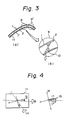
- Fig. 3 is a schematic view illustrating the distribution of the shear stress applied by a bending treatment to the bending treated portion of a smectic liquid crystal in a liquid crystal optical device
- the figure (a) is a schematic view showing an example where a liquid crystal optical device 11 is being subjected to a bending treatment
- each of referential numeral 1 and 1′ represents a flexible substrate bearing electrode layer
- the referential numeral 2 represents a smectic liquid crystal
- the referential numeral 9′ represents the part of the liquid crystal optical device 11 being subjected to a bending treatment
- the figure (b) is a partially enlarged view of the portion subjected to a bending treatment, wherein arrows show distribution of the shear stress applied to the smectic liquid crystal by the bending treatment.
- smectic liquid crystals have a larger modulus of elasticity than nematic liquid crystals, bending treatment is apt to cause a deformation due to the slip occurred between the contacting domain units rather than a uniform deformation.
- the bending direction refers to a direction of a line bounding two planes formed on a surface of a substrate at the time of bending the substrate.
- the bending treatment when substrates exhibiting optical anisotropy, such as uniaxially or biaxially oriented PET, are used, it is preferable to conduct the bending treatment with the bending direction adjusted so that the the bending direction and the optically principal axis (orientation direction ) of the substrates approximately make, on the plane of the substrates, the tilt angle ⁇ of the ferroelectric liquid crystal or 90° - ⁇ .
- Fig. 4 illustrates the relation between the bending direction of a liquid crystal device and a polarizer.
- the referential numeral 11 represents a liquid crystal optical device enclosing a ferroelectric liquid crystal therein
- the referential numeral 12 represents the optically principal axis of substrate
- each of the referential numerals 13 and 14 represents a bending direction of the device
- each of the referential numerals 15 and 16 represents the polarizing axis of the polarizer
- the referential numeral 17 represents the orientation direction of the liquid crystal (darkness) at the time when an electric field is applied in a certain direction
- the referential numeral 17′ represents the orientation direction of the liquid crystal (light) at the time an electric field is applied in the opposite direction.
- a bending treatment along the bending direction 13 makes domains of liquid crystal orient in a direction parallel with the dotted line 13.
- oriented device can be switched between light and dark states by arranging two polarizers outside the device 11 with their polarizing axes 15 and 16 perpendicularly intersecting each other and, subsequently, switching the orientation direction of the liquid crystal between 17 and 17′ by switching the electric field between positive and negative.
- the two polarizers may also be arranged with both of their polarizing axes directed in one direction 15 or 16 to be parallel to each other. In the latter case, the switching between light and darkness is reversed.
- the obtained liquid crystal device can be delivered from the effect of the optical anisotropy by adjusting the bending direction so that the bending direction and the optically principal axis of at least one of the substrates make ⁇ or 90° - ⁇ .
- the orientation by means of the bending treatment can be more effectively performed by heating the liquid crystal optical device to a proper temperature depending on the kind of the liquid crystal.
- the smectic liquid crystal exhibits at least one liquid crystal phase, such as a mixed phase of isotropic phase and smectic A phase, a mixed phase of isotropic phase and chiral smectic C phase, smectic A phase or chiral smectic C phase.
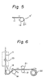
- the above-described orientation by a bending treatment can be conducted by using various kinds of apparatuses and systems. It is generally suitable to use a method of subjecting a liquid crystal optical device to a bending treatment using at least one free rotation roll in the course of continuous move of the liquid crystal optical device, preferably a method of subjecting a liquid crystal optical device to a bending treatment in the course of continuous move of the liquid crystal optical device moving through at least two free rotation rolls.
- Fig. 5 is a schematic view illustrating an embodiment of the orientation method according to the present invention, wherein a liquid crystal optical device 11 is subjected to a bending treatment using one roll 18 in the course of continuous move of the liquid crystal optical device.
- the referential numeral 9′ represents the part of the liquid crystal optical device 11 being subjected to bending treatment.
- the bending degree of the liquid crystal optical device adjusted within generally 5 to 1,000 mm, preferably 10 to 500 mm, as measured as the radius of curvature.
- Too small radius of curvature is apt to damage substrates or to cut electrode structures delicate in pattern and, on the other hand, if the radius of curvature is too large, the shear stress applied to the liquid crystal may become insufficient resulting in a poor orientation state.
- orientation of smectic liquid crystals by means of the above described bending treatment can be performed more effectively and more efficiently by subjecting a liquid crystal optical device to the bending treatment in the course of continuous move of the liquid crystal optical device. Particularly, it can be performed furthermore effectively at a high speed, enabling mass production, by continuously moving the liquid crystal optical device through at least two free rotation rolls to subject the liquid crystal optical device to a bending treatment.
- the moving speed of the liquid crystal optical device during the bending treatment cannot be uniformly defined because it varies depending on the radius of curvature at the bending part, temperature, the kind of the smectic liquid crystal, etc. It is generally sufficient to adjust the speed to the line speed of a continuous production process including a step of film-forming by application and a step of lamination treatment. Therefore, it is possible to equalize all of the line speeds of various steps including the orientation step by a bending treatment, whereby a continuous, high-speed process for mass producing liquid crystal optical devices can be efficiently realized, resulting in an extreme improvement of mass productivity.
- the suitable moving speed of liquid crystal optical device during the bending treatment ranges generally from 0.1 to 50 m/min. (0.16 to 83.3 cm/sec.).
- the moving speed suitable only for bending treatment there is no particular limit in the moving speed suitable only for bending treatment, and the range can be larger that the above-described range.
- the moving speed is too high, some kinds of substrates may suffer a damage, such as cracking, during the bending treatment, and on the other hand, if it is too low, although a sufficient orientation will be attained, the production time will be elongated resulting in a decrease of practicality.
- orientation treatment is performed by conducting bending treatment while cooling liquid crystal from an isotropic phase temperature to a liquid crystal phase temperature, referring to drawings.
- FIG. 6 and Fig. 7 is a schematic view illustrating, as a particularly preferred embodiment of the orientation method according to the present invention, an example of continuous orientation method wherein bending treatment is conducted while cooling liquid crystal from an isotropic phase temperature to a liquid crystal phase temperature.
- the referential numeral 11 represents a liquid crystal optical device
- each of the referential numerals 18 and 19 represents a free rotation roll for applying bending treatment
- the referential numeral 21 represents a pair of support rolls
- the referential numeral 22 represents a winding roll
- the referential numeral 23 represents a heating apparatus
- the referential symbols T1, T2, and T3 represent the temperatures of the heating apparatus 23, the free rotation rolls 18, and the free rotation rolls 19, respectively.
- the referential numeral 11 represents a liquid crystal optical device
- each of the referential numerals 18, 19, and 20 represents a free rotation roll for applying bending treatment
- the referential numeral 23 represents a heating apparatus.
- a liquid crystal optical device 11 is, at first, heated by a heating apparatus 23 to a temperature at which the ferroelectric liquid crystal in the liquid crystal optical device 11 exhibits isotropic phase, in the course of continuous move of the liquid crystal optical device moviug through the heating apparatus 23 adjusted to a temperature T1. Subsequently, in the course of continuous move of the liquid crystal optical device moving from a free rotation roll 18 of a temperature T2 to another rotation roll 19 of a temperature T3, the liquid crystal optical device 11 is then subjected to an orientation treatment by bending treatment using the two free rotation rolls 18 and 19 while cooling the ferroelectric liquid crystal to a temperature at which it exhibits a liquid crystal phase. The obtained oriented product is then moved through between a pair of support rolls 21 and is continuously wound up by a winding roll 22.
- the temperature T1 it is sufficient to adjust the temperature T1 so that the heated liquid crystal optical device 11 can maintain isotropic phase until, at least, the liquid crystal optical device 11 begins to be subjected to bending treatment. It is also sufficient to adjust the temperatures T2 and T3 so that before the conclusion of the bending treatment, the liquid crystal optical device 11 can be cooled to a temperature at which it exhibits a liquid crystal phase.
- the temperatures T2 and T3 may be identical with or different from each other. However, in order to make the control of temperature easy considering the heat capacity of the liquid crystal optical device and to maintain stable operation for a long time, it is generally desirable to maintain the temperature T3 lower than the temperature T2.
- the orientation method of the present invention there is no particular restriction in the arrangement of the free rotation rolls to be used in the orientation by bending treatment.
- it is particularly preferable to conduct the bending treatment as the examples shown in Fig. 6 and Fig. 7, by arranging at least two free rotation rolls in sequential order and continuously moving a liquid crystal optical device through the free rotation rolls.
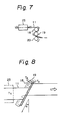
- Fig. 8 is a schematic view illustrating a particularly preferable embodiment of the above-described continuous orientation method according to the present invention wherein bending treatment is conducted with the bending direction inclining at an angle, while cooling the temperature from a isotropic phase temperature to a liquid crystal phase temperature.
- the referential numeral 11 represents a liquid crystal optical device
- each of the referential numerals 18 and 19 represents a free rotation roll
- the referential numeral 23 represents a heating apparatus
- the referential numerals T1, T2, and T3 represent the temperatures of the heating apparatus 23, the free rotation roll 18, and the free rotation roll 19, respectively.
- the liquid crystal optical device 11 in the course of continuous move of the liquid crystal optical device 11, the liquid crystal optical device 11 is heated to a temperature at which the smectic liquid crystal in the liquid crystal optical device exhibits isotropic phase by the heating apparatus 23 adjusted to a temperature T1, and then the liquid crystal optical device 11 is subjected to bending treatment for orientation in the course of continuous move of the liquid crystal optical device 11 moving through the two free rotation rolls 18 and 19 adjusted to temperatures T2 and T3, respectively, while cooling the smectic liquid crystal to a temperature at which it exhibits a liquid crystal phase.
- the two rolls are arranged so that the bending direction of the substrate and the direction right-angled to the principal axis of at least one of the substrate make ⁇ or 90° - ⁇ .
- the number of the rolls is not limited to two but also may be one or three or more. The preferred number is two or more.
- the temperatures T2 and T3 may be identical with or different from each other. However, in order to make the temperature control easy considering the heat capacity of the liquid crystal oprical device, and to maintain stable operation for a long time, it is generally desirable to maintain the temperature T3 lower than the temperature T2.
- the orientation method of the present invention there is no particular restriction in the arrangement of the free rotation rolls to be used in the orientation by bending treatment.
- the method of orienting liquid crystal optical device according to the present invention is extremely advantageous in practical use in that a high degree of orientation can be attained by extremely simple procedures without requiring complicated pretreatment to substrates, etc., for example rubbing treatment or incline deposition treatment; liquid crystal optical devices having excellent high speed response property, contrast ratio, etc. can be obtained in an efficient manner; and a high speed and continuous mass-production system can be easily realized.
- the orientation method of the present invention are, therefore, suitable for orientation method in a production process of various kinds of smectic liquid crystal optical devices with supporting substrates bearing electrodes.
- a substrate having no optical anisotropy such as PES (polyethersulfones), PC (polycarbonates) or PS (polysulfones)
- PES polyethersulfones
- PC polycarbonates
- PS polysulfones
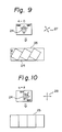
- the liquid crystal molecule 24 inclines from the major axis of the oriented liquid crystal molecule to make an angle, + ⁇ or - ⁇ , between them and exhibits dark state or light state.
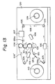
- Fig. 11 is a schematic view illustrating an embodiment of the apparatus for orientation according to the present invention and, at the same time, illustrating an embodiment of the orientation method according to the present invention.
- two belts i.e. a downside belt 108 and an upside belt 108′ , are used as the supporting means for suppoting liquid crystal optical device.
- both of the two belts form their respective loops in a state of a conveyer (endless conveyer).
- the two belts are not necessarily required to form a loop, it is preferable, from the viewpoint of the productivity and convenience in operation, that at least one forms a loop, and it is particularly preferable that both belts form their respective loops.
- a liquid crystal optical device is supported preferably between two belts and is subjected to bending treatment by moving the belts supporting the liquid crystal optical device between them so that the two outer surfaces of the belts by turns come closely into contact with the roll surfaces of at least two heating rolls whereby the liquid crystal in the liquid crystal optical device is oriented to a high degree.
- the supporting structure is not limited to a belt, and any supporting structure similar to belt may be used.
- the heating roll is not particularly limited in number so long as two or more heating rolls are used, and it is generally sufficient to use two to four, preferably three heating rolls.
- the system for moving a belt is not particularly limited. Generally, a moving system by properly arranged driving rolls or the like is suitable. In the apparatus of the present invention, at least one driving roll is provided to move the belts.
- driving rolls may also serve as heating rolls.
- the heating rolls are not particularly limited in the materials, and common materials, for example metals such as stainless steel or the like may be suitably used, particularly stainless steel or the like are preferable.
- the material for driving rolls (including those used also as heating rolls) is not particularly limited so long as it can provide sufficient driving force and conforms to condition in use.
- the preferred generally include rubbers and ones similar to rubbers, and the particularly preferred materials are rubbers.
- heating rolls 101 to 103 are arranged so that each roll comes into contact with another one in the order of the arrangement, and there is also provided a support roll 104.
- the heating roll 102 doubles as a driving roll.
- Each of the belts 108 and 108′ respectively forms an independent loop and circulate through the heating rolls and the guide rolls 105. In the course of the circulation, the liquid crystal optical device supported between the belts is subjected to bending treatment during the move through each heating roll.
- liquid crystal optical device 126a is sandwiched between the upper belt 108′ and the under belt 108, and moves, in the state supported between the belts, through between the heating roll 101 and the heating roll (driving roll) 102 and between the heating roll (driving roll) 102 and the heating roll 103 in order while being oriented by bending.
- the two belts 108 and 108′ are separated from each other in different directions to collect an oriented liquid crystal optical device 126b.
- the points of supply and collection and the moving system (the route, etc.) of the belts 108 and 108′ are not limited to those shown in Fig. 11 and, for example, the systems which are shown in Figs. 13 to 15 and will be described later may also be suitably employed.
- liquid crystal optical may also be used in a form of a sufficiently lengthy device.
- the lengthy liquid crystal optical device is continuously supplied from a supply roll 109 to which the device has been wound in a roll state and is continuously collected being wound up by a winding roll 110.
- the oriented liquid crystal optical device may also be discharged from the orientation system without using a winding roll but by using driving rolls other than those shown in Fig. 11, leaving the sheet-form of the device as it is.
- three tension controllers 106 and one panel angle controller 107 are provided.
- the tension controllers 106 in a proper arrangement and applying a proper tension to the belts 108 and 108′, the slip between driving roll (heating roll 102) and the belts 108 and 108′ can be prevented and the bending treatment for a high degree of orientation can be efficiently performed. Therefore, it is preferable to provide such tension controllers in a proper arrangement.
- the preferred driving roll (heating roll 102) is a rubber roll.
- the panel angle controller is provided to control the panel angle of the liquid crystal optical device to be subjected to orientation, whereby a high degree of orientation of liquid crystal by means of bending treatment can be more effectively performed.
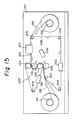
- Fig. 13 shows another embodiment of orientation method using an apparatus similar to that used in the method shown in Fig. 11.
- tension is controlled by passing the belts 108 and 108′ respectively through the other two tension controllers. That is, in the embodiment shown in Fig. 13, the belts 108 and 108′ move taking a route partially different from that of the embodiment shown in Fig. 11. Accordingly, the arrangement of the guide rolls 105 is altered. Further, in the embodiment shown in Fig. 13, the liquid crystal optical device is taken out after it comes out through between the heating roll (driving roll) 102 and the heating roll 103.
- the heating roll 101 heats a liquid crystal optical device to a temperature at which the liquid crystal in the device exhibits isotropic phase, and subsequently, the heating roll 102 (driving roll) and the heating roll 103 control the temperature of the liquid crystal optical device so that the liquid crystal exhibits a liquid crystal phase, such as a mixed phase of isotropic phase and smectic A phase or a mixed phase of isotropic phase and chiral smectic C phase. It is generally preferable that the heating roll 102 adjusts the temperature of the liquid crystal optical device to a temperature 5 to 10°C lower than the temperature at which phase transition of the liquid crystal to isotropic phase occurs.
- the spaces between the heating rolls 101 and 102 and between the heating rolls 102 and 103 are not particularly limited.
- the bending direction of bending treatment on the surface of substrate is adjusted so that the bending direction and the direction of the optically principal axis (orientation direction ) of substrate approximately make the tilt angle ⁇ of ferroelectric liquid crystal used or 90° - ⁇ , or the bending direction and the longitudinal direction of substrate approximately make the tilt angle ⁇ of ferroelectric liquid crystal used or 90° - ⁇ .
- Bending direction means the direction of the straight line in which two planes of a substrate formed by bending the substrate intersect.
- orientation direction can be suitably conducted by using a panel angle controlling device. That is, orientation direction can be constantly adjusted to be uniform by using a panel angle controlling device in which the liquid crystal optical device 126a is placed on the downside belt 108 with the angle (a) adjusted as shown in Fig. 17.
- the control of orientation direction is also applicable to the continuous (supply) orientation treatment for lengthy liquid crystal optical devices shown, as examples, in Fig. 14 to Fig. 16.
- the degree of bending liquid crystal optical device in the bending treatment is as described above.
- the orientation method of the present invention is also applicable to liquid crystal optical devices of cut-sheet type and therefore, a plural number of liquid crystal optical devices can be efficiently and continuously oriented in a high speed and in a mass-production scale.
- the orientation method of the present invention applicable to an extensive range of liquid crystal materials including low molecular weight liquid crystals, polymer liquid crystals, and mixtures thereof, it is preferable to employ an operation system in which the orienting speed is adjusted by controlling the rotating speed of heating rolls (driving rolls). Also, the orienting speed may be controlled by directly driving each roll.
- the shear force generated by bending can be controlled by properly adjusting the curvature at the time of bending a liquid crystal optical device.
- the adjustment of the curvature can be effectively and easily accomplished by arranging the heating rolls 101 and 103 so that they can move round the heating roll 102 (driving roll) to either side at the angle of about 45° or less.
- Fig. 12 illustrates the case where both of the moving angle ⁇ 1 of the first heating roll 101 and the moving angle ⁇ 2 of the third heating roll 103 are adjusted to 0°
- the largest shear force is obtainable in the case of (b) and on the other hand, the smallest shear force is obtainable in case of (c).
- FIG. 13 to Fig. 15 schematically illustrates an embodiment of the orientation method according to the present invention.
- the orientation apparatus shown in Fig. 13 to Fig. 15 may be fundamentally identical with that shown in Fig. 11. That is, the same apparatus can be used by altering the moving system (route) of the belts 108 and 108′ , altering accordingly the point of collecting liquid crystal optical devices or the system of supplying and collecting them, and moving the position of some of the guide rolls 105.
- liquid crystal is heated to its isotropic phase temperature by a heating roll 101 and then adjusted to its liquid crystal phase temperature by a heating roll 102 (driving roll) and, at the same time, the liquid crystal is oriented by the two heating rolls.
- This method is suitably applicable to liquid crystal materials which are relatively easy to orient. Unnecessary decrease in temperature can be prevented by adjusting the space between the heating rolls 101 and 102 to 3 mm or less as described above.
- some or all of the guide rolls 105 can be secured at arbitrary points in the side wall plate 120 and further, when altering the number of the heating rolls and the length of contacting portions in which a liquid crystal optical device contacts to heating rolls, the positions of the guide rolls 105 can be properly moved to form a desired loop of belt (conveyer).
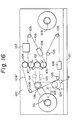
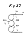
- FIG. 14 and Fig. 15 shows a continuous method of orienting a lengthy liquid crystal optical device 126 by using three heating rolls.
- orientation by bending treatment is conducted by using substantially two heating rolls among the three heating rolls in the same manner as in the method shown in Fig. 13.
- orienting speed is generally controlled by controlling the rotating speed of winding roll 110.
- Fig. 16 is a front view schematically showing the construction of the whole orientation apparatus of the present invention.
- Heating rolls 101 to 103 are generally used at 40 to 120°C .
- the shape of heating rolls are not particularly limited and, for example, rolls having a diameter of about 10 to 500 mm and a roll length of about 10 to 2000 mm as effective length may be suitably used.
- the heating rolls 101 and 103 are not particularly limited in material and generally, those made of mirror-finished stainless steel may be suitably used. With regard to the material of the heating roll 102 which is to be used as a driving roll according to circumstances, a roll having a surface layer made of rubber may be suitably used, and the sufficient thickness of the rubber is generally about 3 mm.
- the rotating speed of the heating rolls variable in the range about 0 to 50 m/min. as measured as the linear velocity of the belts 108 and 108′ .
- the rotation of the heating rolls or the movement of the belts 108 and 108′ is conducted by the method using the heating roll 102 as a driving roll or the method using the winding roll 110 as a driving roll as described above, generally, they are not limited to these methods.
- the spaces between the heating rolls 101 and 102 and between the heating rolls 102 and 103 are preferably adjusted to about 0.1 to 20 mm. As described above, the heating rolls 101 and 103 are arranged so that they can move round the heating roll 102 to either side at a desired angle with the maximum of about 45° .
- the support roll 104 not only supports the supplied liquid crystal optical device but also controls the entry angle thereof.
- the support roll 104 is not limited in material, those made of mirror-finished stainless steel may be suitably used.
- the roll may be generally about 10 to 500 mm in diameter and 10 to 2000 mm in roll length (effective length).
- the guide rolls 105 are not particularly limited in material and generally, those made of aluminum will work sufficiently. With regard to the shapes of the guide rolls 105, the rolls may be generally about 10 to 500 mm in diameter and about 10 to 2000 mm in roll length (effective length). The guide rolls 105 may be properly arranged at desired positions according to the orientation method by securing generally to a side-wall plate 120.
- the panel angle controlling device 107 serves to adjust the arrangement of supplied liquid crystal optical device on the downside belt 108, i.e. panel angle "a", so that the orientation direction and the optically principal axis of the substrate used approximately make the tilt angle of the liquid crystal ⁇ or 90° - ⁇ .
- the range of angles in which the panel angle is to be adjusted may be generally set to from 0 to 90° .
- Placement of liquid crystal optical devices on the downside belt 108 may be generally conducted by using one-touch lever system.
- the widths of the belts 108 and 108′ may be generally from about 10 to 2000 mm, and the thickness from about 20 to 500 ⁇ m.
- the materials are not particularly limited and include, for example plastic films of PET, PES, PI, PP, PS or the like and mixed materials thereof with an inorganic filler such as ceramics or metals. Also, these may be coated with aluminum or the like.
- the winding roll 110 and supply roll 109 may be generally about 50 to 300 mm in diameter and about 100 to 2000 mm in length. These rolls may be equipped with their respective electromagnetic brakes if needed.
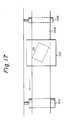
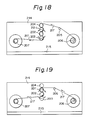
- Fig. 18 is a front view schematically showing the construction of an example of the apparatus for orienting the above-described lengthy liquid crystal display device.
- This apparatus comprises three heating rolls 201 to 203, one support roll 204, one guide roll 205, one supply roll 206, and a winding roll 207.
- the liquid crystal display device supplied from the supply roll 206 is introduced to the upper part of the support roll 204 by the guide roll 205 at a proper angle.
- the liquid crystal display device 217 is then securely fixed to the first heating roll. Thereafter, it moves round the first, the second, and the third heating rolls in order while closely contacting its face and back by turns to the heating rolls and is then wound up by the winding roll 207 from the lower part of the third heating roll.
- liquid crystal display device 217 may take a different route as that described above: that is, liquid crystal display device 217 may also be wound up by the winding roll directly after it comes out through between the second and third heating rolls, by moving it through between the support roll 204 and the first heating roll and subsequently, moving it while closely contacting it to only the first and second heating rolls. In this case, substantially, orientation was performed by bending using only two heating rolls, i.e. the first and second heating rolls, among the three heating rolls.
- each heating rolls individually. It it preferable to heat liquid crystal display device by the first heating roll to a temperature at which the liquid crystal material exhibits isotropic phase and then decrease the temperature by the second and third heating rolls to a temperature at which the liquid crystal material exhibits a liquid crystal phase so that the liquid crystal can be oriented. It is generally appropriate to control the temperature of the third heating roll about 5 to 10°C lower than the temperature of the second heating roll.
- the spaces between the first and the second heating rolls and between the second and the third heating rolls are not particularly limited, it is effective to adjust the spaces to 3 mm or less for preventing the liquid crystal display device from cooling lower than the temperature of the next roll, whereby a high degree of orientation can be attained by merely moving the liquid crystal display device round the heating rolls with its surface closely contacted to that of the heating rolls.
- the orientation state of liquid crystal material depends on the combination of liquid crystal material, orienting speed, bending force, etc.
- orienting speed it is preferable to make it variable so that a wide range of liquid crystal materials including low molecular weight liquid crystals , polymer liquid crystals, and mixtures thereof can be oriented by this method.
- a too large orienting speed may sometimes cause insufficient orientation or injury to substrates and on the other hand, if orienting speed is too small, though a sufficient orientation can be performed, the time required for the orientation may sometimes increase resulting in a decrease in practicability.
- the orienting speed is adjusted to a speed identical with those of the steps of producing the liquid crystal display device, for example the step of applying and drying liquid crystal material, lamination step, or the like, a continuous process of producing liquid crystal display device at a high speed will become easy to practice efficiently, resulting in an extreme improvement of mass-productivity.
- the preferred diameter is generally 10 to 500 mm
- the preferred roll length which is not particularly limited, is generally 10 to 2000 mm as measured as the effective length.
- the materials of the heating rolls may be any of metals, ceramics, and rubbers, and the preferred are those having even surfaces and small temperature distributions.
- the second heating roll is preferably made of rubber for the purpose of preventing slip between the roll and the liquid crystal display device.
- the rotating speed of the heating rolls it is preferable to make it variable within the range of 0 to 50 m/min. as measured as the linear velocity of the heating rolls.
- the particularly preferred range is 0.2 to 20 m/min. It is preferable to control the rotating speed by using the winding roll as a driving roll.
- the heating rolls it is generally preferable to adjust the spaces between the first and second heating rolls and between the second and third heating rolls to 0.1 to 20 mm.
- the particularly preferred space is 0.5 to 5 mm.
- the preferred diameter is generally 10 to 500 mm
- the preferred roll length which is not particularly limited, is generally 10 to 2000 mm as measured as the effective length.
- the support roll 204 and the guide roll 205 there is no particular limit in the materials of the support roll 204 and the guide roll 205, and these rolls may be of a construction in which they can be used as supplemental heating means.
- the preferred diameter is generally 50 to 300 mm
- the preferred roll length (effective length) is generally 10 to 1000 mm.
- the winding speed variable in the range of 0 to 50 m/min., and the particularly preferred winding speed is 0.2 to 20 m/min. It is desirable to control the orienting speed by varying the winding speed.
- heating rolls While the above description centers on the subjects of the above description are apparatuses using three heating rolls, it is also possible to use one, two or more than 3 heating rolls. The number of heating rolls may be properly selected depending on conditions of other elements including the liquid crystal material, orienting speed, bending force, etc.
- the orientation apparatus of the present invention is simple in construction and is capable of orienting efficiently various kinds of liquid crystal optical devices to a high degree by a simple operation.
- a flexible substrate bearing electrode layer is produced by using a film of a transparent polyethersulfone (PES) of about 100 ⁇ m in thickness as a flexible substrate and layering an ITO, which is a transparent conductive layer, of about 700 ⁇ in thickness on one surface of the PES film.
- PES transparent polyethersulfone
- ITO transparent conductive layer
- a ferroelectric polymer liquid crystal having the repeating unit represented by the following formula and the following properties and exhibiting isotropic phase by using a bar coater to form a layer of of about 2.5 ⁇ m in thickness after heating the ferroelectric polymer liquid crystal to 100°C .
- a liquid crystal device of 10 cm in width and 30 cm in length was produced by using a film of PES of about 100 ⁇ m in thickness as the opposite substrate and laminating the substrate on the surface of the above-described application film of the above ferroelectric polymer liquid crystal.
- liquid crystal molecules are randomly oriented.
- the liquid crystal optical device was continuously subjected to bending treatment using a group of rolls consisting of three free rotation rolls of 30 mm in diameter which were maintained to the atmospheric temperatures shown in Table 1 and were arranged with the distance between the centers adjusted to 40 mm.
- the value of the degree of orientation A shown in Table 1 was obtained according to the general measuring method commonly known.
- each of the liquid crystal optical devices subjected to the above bending treatment was arranged between and in parallel to two polarizers having polarizing axes meeting at right angles to construct a liquid crystal device. Then, while white light from a halogen lamp was radiated to the liquid crystal device, the liquid crystal device was rotated round the spot of the light and, at the same time, the variation in the strength of transmitted right was measured.
- the degree of orientation A means the ratio of the maximum strength (I max ) to the minimum strength (I min ) .
- a biaxially oriented PET (polyethyleneterephthalate) of 125 ⁇ m in thickness bearing ITO (thickness of ITO: about 1000 ⁇ ) was used as flexible substrate bearing electrode layer, and the following polyoxirane-based ferroelectric polymer liquid crystal was applied on the substrate by the method shown in Fig. 1.
- a solution of the liquid crystal dissolved in a solvent (dichloromethane) to 10 % by weight was applied on the substrate with a roll coater as shown in Fig. 1 to a thickness of about 15 ⁇ m, and then the solvent was evaporated to form a film of liquid crystal yet to be oriented that had a thickness of 1.5 ⁇ m.
- orientation by bending treatment was conducted by continuously moving the resulting laminate through two free rotation rolls (diameter: 20 mm, distance between centers: 40 mm) using the method shown in Fig. 6.
- the liquid crystal optical device yet to be oriented was previously heated to a temperature T1 by a heating apparatus 23 and then sequentially cooled to a temperatures T2 and T3 while being subjected to bending treatment by the two free rotation rolls 18 and 19.
- the degree of orientation A after cooling to 25°C was about 160. Further, the degree of orientation A ranged between 150 and 170 over the width of the substrate of 15 cm, showing that the orientation procedure was well and uniformly performed.
- the above method is suitable for mass-production, and it could be continuously conducted together with the step of applying liquid crystal and lamination step, simultaneously.
- Example 2 The procedure of Example 2 was repeated with the exception that a low molecular weight liquid crystal, DOBAMBC (p-decyloxybenzilidene-p′ -amino-2-methylbutyl cinnamate): was supported between the same two PES substrates bearing ITO film as those used in Example 1 to produce a liquid crystal device yet to be oriented that had a width of 20 cm, a length of 150cm, and a thickness of 3 ⁇ m, and the obtained liquid crystal device yet to be oriented was subjected to the same orientation treatment as that conducted in Example 2.
- T1 120°C
- T2 100°C
- T3 80°C and supply speed: 4 cm/sec.
- the degree of orientation A measured immediately after moving out from the group of cooling rolls was about 70.
- the uniformity of orientation was such that the degree of orientation A ranged from 55 to 80 over the width of the film of 20 cm, showing practically sufficient uniformity.
- the orientation method of the present invention is an excellent orientation method for both of low molecular weight ferroelectric liquid crystals and polymer ferroelectric liquid crystals. Further, it was also confirmed that the method of the present invention is extremely effective for, particularly, ferroelectric polymer liquid crystals having a wide range of temperature wherein the liquid crystals exhibit a mixed liquid crystal phase, such as a mixed liquid crystal phase of isotropic phase and a smectic phase.
- a 10 % dichloromethane solution of a mixture containing the low molecular weight ferroelectric liquid crystal shown below, an epoxy resin (MG 150 produced by Nippon Pernox Co., Ltd.) as main agent, and a hardening agent in a weight ratio of 3:1:1 was applied as a layer on a substrate of biaxially oriented polyester film (CELEC K-US produced by Daicel Chemical Industries, Ltd.) bearing ITO by applying the solution using a micro-gravure coater.
- the original film of substrate had a width of 210 mm, a length of 5 m, and a thickness of 100 ⁇ m. After evaporating the solvent, the thickness of the liquid crystal-epoxy resin mixture was measured to be about 3 ⁇ m.
- the came substrate as above-described substrate having nothing applied on it was laminated as the opposite substrate by two pressure rolls of 80 mm in diameter and 40 cm in length which were heated to 40°C and applied with an air pressure of 2 kg/cm2, to produce a device yet to be oriented.
- optically principal axis of the original film of substrate was measured as the direction of the film in which the strength of a transmitted light was minimized while rotating the film between crossed polarizers, the optically principal axis of the original substrate was measured to have a direction making an angle of 32° with the MD direction.
- each of the substrates had an orienting direction making an angle with the MD direction (the longitudinal direction of a film)
- the device obtained by lamination had principal axes in two directions.
- the contrast ratio was measured to be 36 at 25°C between crossed polarizers and at ⁇ 5 V of applied voltages.
- the high contrast ratio obtained may be attributable to the fact that the angle made by lamination between the two principal axes was as large as 64° whereby decreasing the effect of the main axis other than that described above in the procedure of orientation treatment.
- a 20 % by weight dichloromethane solution containing a ferroelectric liquid crystal was applied using a direct-gravure coater on a substrate of uniaxially oriented PET film (CELEK KT-LC produced by Daicel Chemical Industries Co., Ltd., width: 30 cm, length: 10 m, thickness: 125 ⁇ m) bearing ITO to form a liquid crystal layer of about about 2 ⁇ m in thickness. Subsequently, on the resulting substrate, the same substrate as the original substrate was laminated using the same pressure roll as that used in Example 1. Because the angle between the direction of the optically principal axis of the substrate and the MD direction was not more than 5° , bending was conducted by the method shown in Fig.
- contrast ratio was measured by supporting a device cut out into a size of 30 cm x 30 cm between two polarizing plates having their respective polarizing axes in the MD direction of the film and in the direction intersecting perpendicularly to the MD direction, the contrast ratio was measured to be 75 at 25°C and at applied voltages of ⁇ 10 V, which value shows the extremely high efficiency of the device produced in this Example.
- a 10 % by weight chloroform solution of a mixture containing the ferroelectric polymer liquid crystal used in Example 5 and the epoxy resin (main agent) and the hardening agent both used in Example 4 in a weight ratio of 4:1:1 was applied on a substrate of a PES film.
- SUMILITE FST produced by Sumitomo Bakelite Co., Ltd., width: 15 cm, length: 80 cm, thickness: 100 ⁇ m
- the solvent was then evaporated to obtain a layered film of about 5 ⁇ m in thickness.
- the obtained device was subjected to bending treatment by the method shown in Fig. 15.
- thermoplastic resin As thermoplastic resin, the following three were used.
- the ratio of the amounts of liquid crystal component used and thermoplastic resin used were uniformalized to 2:1 in weight ratio.
- the obtained mixtures were respectively dissolved in dichloromethane to form 10 % by weight solutions.
- PES polyethersulfone substrates (width 150 mm, thickness: 125 ⁇ m) bearing their respective ITO were used to be provided to both sides of each liquid crystal film.
- the obtained substrate was laminated with an opposite substrate by passing them together through between two pressure rolls. After the lamination, the ferroelectric liquid crystal composition had a thickness of about 5 ⁇ m.
- each of the samples produced above was used as the liquid crystal optical device 126a and was oriented by subjecting it to bending treatment using the apparatus and the corresponding orientation method shown in Table 2 by the number of figure, under the condition shown in Table 2. Because PES was used as flexible substrate, the panel angle a was adjusted to 0° . Each of the samples subjected to orientation treatment had been previously cut from the obtained sheet of 15 cm in width into a form of cut sheet having a length of 20 cm.
- Example 11 A2/B2 98 70 50 6 0 0 72 Fig. 11
- Example 12 A2/B3 105 80 60 2 +30 -30 48 Fig. 11
- Each of the above contrast ratio was measured at the applied voltage of ⁇ 10 V.
- ⁇ moving angle of roll
- a low molecular weight ferroelectric liquid crystal and the ferroelectric polymer liquid crystal (3) used in Examples 7 to 12 were mixed in a molar ratio of 7:3 to obtain the mixture liquid crystal exhibiting the following phase transition behavior.
- a mixture containing the mixed liquid crystal and polyvinylchloride in a weight ratio of 3:2 was dissolved in tetrahydrofuran (THF) to form a 15 % by weight solution.
- THF tetrahydrofuran
- the obtained solution was applied on a substrate of uniaxially oriented PET (thickness: 100 ⁇ m, width: 200 mm) bearing ITO electrode by screen-printing method and after evaporation of the solvent, a composite film of about 6 ⁇ m in thickness was obtained.
- the panel angle a was adjusted to 16° , which is equal to tilt angle.
- a 20 % by weight dichloromethane solution of the ferroelectric polymer liquid crystal was applied on a PES film (SUMILITE FST produced by Sumitomo Bakelite Co., Ltd., width: 15 cm, length: 10 m, thickness: 100 ⁇ m) bearing ITO electrode using a gravure coater, and then the solvent was evaporated to obtain a liquid crystal layer of about 2 ⁇ m in thickness.
- the same PES film was laminated to produce a liquid crystal optical device to be supplied.
- PES polyethersulfone
- SUMILITE FST produced by Sumitomo Bakelite Co., Ltd.
- liquid crystal material As the liquid crystal material to be supported between two substrates bearing their respective, transparent electrodes, a mixture which contains a ferroelectric polymer liquid crystal having the following repeating unit and the following property and an epoxy-based adhesive (KER 1001 produced by Koei Kagaku Co., Ltd., weight ratio of main agent to hardening agent: 4:1) in a weight ratio of 3:1 was used.
- KER 1001 produced by Koei Kagaku Co., Ltd., weight ratio of main agent to hardening agent: 4:1
- a solution of the liquid crystal material dissolved in a solvent, 1,1,1-trichloroethane to a concentration of the liquid crystal material of 10 % by weight was applied on ITO film coating one substrate using a micro gravure roll, and the solvent was then evaporated out. Further, the same substrate as that described above was laminated on the obtained substrate to produce a liquid crystal device having a width of 15 cm, a length of 2 m, and a thickness of liquid crystal layer of 2.5 ⁇ m.
- the obtained device was oriented by using the orientation apparatus of the present invention under the following condition.
- the first and second rolls were heated.
- the first heating roll used had a diameter of 80 mm and a roll length of 300 mm, and its material was a cold finished steel bar the surface of which had been hard-chrome plated.
- the second heating roll used had a diameter of 80 mm and a roll length of 300 mm, and its material was a cold finished steel bar round which silicone rubber had been wound.
- the first heating roll and the second heating roll were spaced by from each other 2.0 mm.
- the temperature of the first heating roll T1 was adjusted to 86°C
- the temperature of the second heating roll T2to 60°C the device supply speed, i.e.
- the orientation speed to 10 m/min. Because two heating rolls were used for heating, the angle ⁇ 1 between the first roll and the second heating roll was adjusted to 0° , and also the angle ⁇ 2 between the second roll and the third roll was adjusted to 0° .
- the degree of orientation was evaluated by measuring contrast ratio (CR) at applied voltages of ⁇ 10 V, and the contrast ratio was measured to be 43.
- contrast ratio was measured at four points distributed with a space of 3 cm between the points in the width direction of the device having a width of 15 cm in order to examine the uniformity of contrast ratio, the contrast ratios at the four points were measured to be respectively 47, 44, 42, and 39, and the average was 43. When it was measured at ten points uniformly distributed in the direction of length of 2 m, all of the measured contrast ratios were 40 or more, showing an orientation having a good uniformity.
- liquid crystal material a blend of ferroelectric polymer liquid crystals and ferroelectric low molecular weight liquid crystals was used.
- the structures of the above liquid crystals and the blending ratio (mol %) were as follows.
- Example 16 To the blend was further added the same adhesive as that used in Example 16 in the same ratio. Further, the obtained blend was dissolved to a concentration of liquid crystal material of 20 % by weight with the same solvent used in Example 15. The obtained solution was applied on the ITO coating a substrate by kiss-roll coating method with a gravure roll and was then dried. Subsequently, the same substrate was laminated on the above obtained substrate to produce a liquid crystal device having a width of 15 cm, a length of 2.5 m, and a thickness of liquid crystal film of 2 ⁇ m.
- the obtained liquid crystal device was continuously oriented by the method shown in Fig. 18 using three heating rolls.
- the first heating roll used had a diameter of 100 mm and a roll length of 800 mm, and its material was a cold finished steel bar the surface of which had been hard-chrome plated.
- the second heating roll used had a diameter of 100 mm and a roll length of 800 mm, and its material was a cold finished steel bar round which a rubber had been wound.
- the third heating roll used had a diameter of 100 mm and a roll length of 800 mm, and its material was a cold finished steel bar round which a rubber had been wound.
- the first heating roll and the second heating roll were spaced from each other by 1.5 mm.
- the second heating roll and the third heating roll were spaced from each other by 2.0 mm.
- contrast ratio was measured at applied voltages of ⁇ 10 V by the same procedure as that employed in Example 15, all contrast ratios were 68 or more, showing an orientation having a good uniformity.
- Example 17 The same liquid crystal device as that produced in Example 16 was subjected to orientation treatment using the same apparatus as that used in Example 16 with the proviso that the orientation condition was changed, and degree of orientation of the oriented device was then measured. The orientation condition and the obtained contrast ratio were shown in Table 3. The obtained results were good. Table 3 T1 (°C) T2 (°C) T3 (°C) ⁇ 1 (° ) ⁇ 2 (° ) Contrast ratio Example 17 90 80 75 0 0 72 Example 18 85 80 75 -35 +40 68 Example 19 90 80 70 -15 +10 70 Example 20 85 75 70 +40 -45 77
- a PES substrate (thickness: 100 ⁇ m, width: 300 mm, length: 10 m, rolled type) bearing ITO was used as flexible substrate bearing electrode layer, and a 8 % by weight solution of the following liquid crystal composition dissolved in dichloromethane was applied on the electrode surface of the substrate.
- Liquid crystal material Liquid crystal material
- CEMEDINE HIGH-SUPER epoxy-based adhesive produced by Cemedine Co., Ltd.
- an opposite PES substrate bearing ITO of the same kind as that described above was laminated on the liquid crystal layer using a pair of pressing rolls (One roll is a chrome-gilt iron roll, and the other is made of rubber. Both have a diameter of 80 mm and a length of 500 mm.) to produce a liquid crystal optical device.
- the obtained device had a liquid crystal layer of a thickness of about 3 ⁇ m.
- the liquid crystal optical device was oriented by a bending treatment using a group of rolls consisting of three free rotation rolls 302, 303, and 304 shown in Fig. 20 (Every roll is a chrome-gilt iron roll having a diameter of 80 mm.).
- the orientation by bending treatment was conducted while heating the liquid crystal optical device rapidly to the isotropic phase temperature by the first roll 302 and then cooling it to the SmA phase temperature by the second and third rolls 303 and 304 successively.
- the adhesive was completely cured about five minutes after the above orientation treatment.
- the liquid crystal optical device was then cut off to a length of 30 cm, and the obtained cut-sheet type of crystal optical device was sandwiched between two polarizing plates having polarizing axes perpendicularly intersecting each other.
- the contrast ratio was measured by applying d.c. voltages of ⁇ 5 V between the upper and lower electrode layers, the greatest value of 110 was obtained by arranging the liquid crystal optical device so that the orientation direction and one of the polarizing axes approximately make an angle of 22.5° . After measuring the contrast ratio at various measuring points, it was proved that a high degree of orientation, i.e. contrast ratios of 100 or more, was attained over the whole device.
- Example 21 In the same manner as that described in Example 21, the same liquid crystal composition as that used in Example 21 was applied on a uniaxially oriented PET substrate bearing ITO and having an optical main axis in the longitudinal direction, and the same opposite, uniaxially oriented PET substrate bearing ITO was laminated on the obtained liquid crystal layer, to obtain a liquid crystal optical device.
- the obtained liquid crystal optical device was then cut into pieces of 30 cm in length, and the obtained cut sheets were subjected to orientation treatment one by one by using an apparatus shown in Fig. 21 which consists of three free rotation rolls 302, 303, and 304.
- the liquid crystal optical device 319 yet to be oriented was supported between two supporting belts 321, and was heated to a temperature T1 by the first roll 302 which serves as a heating roll and then cooled to a temperature T2 and successively to T3 by the second and third rolls 303 and 304 which serve as a cooling roll, during bending the device 319.
- the free rotation roll 302 had been shifted to the plus direction by an angle ⁇ round the rotating axis of the roll 303, and the free rotation roll 304 had been shifted to the minus direction by a roll-arrangement angle ⁇ .
- the liquid crystal optical devices 319 yet to be oriented were arranged on the supporting belt 321 so as to tilt by a device-arrangement angle ⁇ as shown in Fig. 22.
- the support rolls 318 used were free rotation rolls made of chrome-gilt iron and were 40 mm in diameter and 500 mm in width
- the free rotation rolls 302 and 303 used were free rotation rolls made of chrome-gilt iron and were 80 mm in diameter and 500 mm in width
- the free rotation roll 304 used was of the same kind as that of the free rotation rolls 302 and 303 and was attached to a driving motor.
- the supporting belts 321 used were polycarbonates sheets of 75 ⁇ m in thickness and 480 mm in width.
- the spaces between the free rotation rolls 302 and 303 and between the free rotation rolls 303 and 304 were adjusted to 1 mm, the roll-arrangement angle ⁇ was adjusted to 45° , and the device-arrangement angle ⁇ was adjusted to 22.5° .
- the contrast ratio was measured to be as good as 135 at applied voltages of ⁇ 5 V when the contrast ratio was measured with the oriented device arranged between crossed polarizers so that the optical main axis of the PET substrate and the polarizing axes of the polarizing plates are at right angles and are parallel to each other.
- a cut-sheet of liquid crystal optical device of 30 cm square was cut from the liquid crystal optical device 319 yet to be oriented that had bee produced in Example 21, and the whole cut-sheet device was then subjected to a bending treatment by forcing it to vibrate (1.5 Hz, amplitude: 3 cm) as shown in Fig. 23 with one side of the cut-sheet device secured by a jig 322.
- the cut-sheet device was heated prior to the bending treatment to a temperature at which the liquid crystal exhibits isotropic phase by exposing the device to hot-air of about 120°C using a blower equipped with a heater, and subsequently the device was rapidly cooled in an atmosphere of room temperature while vibrating it.
- the liquid crystal transferred to SmA phase causing clouding, but the cloudiness was cleared by the time it was cooled to room temperature by several vibrations.
- the contrast ratio was measured using cross-Nicols to be about 70 at the side secured with the jig and about 140 at the opposite side. Further, even at the center part, the contrast ratio was measured to be 120 or more, and these facts proved that sufficient orientation was attained over the whole device.
- a PC (polycarbonate) substrate (thickness: 100 ⁇ m, width: 20 cm, length: 20 m, rolled type) bearing ITO was used as flexible substrate bearing electrode layer, and a 10 % by weight solution of the following liquid crystal composition dissolved in dichloromethane was applied on the electrode surface of the substrate using a direct gravure coater. After drying, the obtained substrate had a liquid crystal layer of 2.5 ⁇ m on the electrode surface.
- Liquid crystal material Liquid crystal material
- CEROMEC SUPER Y 862-1 produced by Cemedine Co., Ltd.
- Liquid crystal material : Adhesive 70:30 (weight part)
- the same PC substrate bearing ITO as that described above was laminated on the liquid crystal layer to obtain a liquid crystal optical device.
- the obtained liquid crystal optical device 301 was subjected to orientation treatment by moving it through a heating furnace 307 of a temperature T1 and a group of rolls consisting of two free rotation rolls 302 and 303, and the adhesive was subsequently cured by irradiating UV light using a metal halide lamp 324 of 400 W.
- the contrast ratio was measured at room temperature using crossed polarizers to be as good as 85 at applied d.c. voltages of ⁇ 5 V.
Landscapes
- Physics & Mathematics (AREA)
- Nonlinear Science (AREA)
- Mathematical Physics (AREA)
- Chemical & Material Sciences (AREA)
- Crystallography & Structural Chemistry (AREA)
- General Physics & Mathematics (AREA)
- Optics & Photonics (AREA)
- Spectroscopy & Molecular Physics (AREA)
- Engineering & Computer Science (AREA)
- Mechanical Engineering (AREA)
- Liquid Crystal (AREA)
Applications Claiming Priority (8)
| Application Number | Priority Date | Filing Date | Title |
|---|---|---|---|
| JP15951088A JPH0816753B2 (ja) | 1988-06-29 | 1988-06-29 | 液晶光学素子の配向方法 |
| JP159510/88 | 1988-06-29 | ||
| JP208222/88 | 1988-08-24 | ||
| JP20822288A JP2648342B2 (ja) | 1988-08-24 | 1988-08-24 | 液晶光学素子の配向方法 |
| JP1007704A JP2525888B2 (ja) | 1989-01-18 | 1989-01-18 | 液晶光学素子の配向方法及びその配向装置 |
| JP7704/89 | 1989-01-18 | ||
| JP5522489A JPH02235023A (ja) | 1989-03-09 | 1989-03-09 | 液晶光学素子の配向装置 |
| JP55224/89 | 1989-03-09 |
Publications (3)
| Publication Number | Publication Date |
|---|---|
| EP0348939A2 true EP0348939A2 (fr) | 1990-01-03 |
| EP0348939A3 EP0348939A3 (en) | 1990-09-12 |
| EP0348939B1 EP0348939B1 (fr) | 1995-02-15 |
Family
ID=27454771
Family Applications (1)
| Application Number | Title | Priority Date | Filing Date |
|---|---|---|---|
| EP89111770A Expired - Lifetime EP0348939B1 (fr) | 1988-06-29 | 1989-06-28 | Procédé pour orienter un dispositif optique à cristal liquide et appareil pour l'utilisation de ce procédé |
Country Status (3)
| Country | Link |
|---|---|
| US (1) | US5069533A (fr) |
| EP (1) | EP0348939B1 (fr) |
| DE (1) | DE68921103T2 (fr) |
Cited By (5)
| Publication number | Priority date | Publication date | Assignee | Title |
|---|---|---|---|---|
| WO1991020012A1 (fr) * | 1990-06-14 | 1991-12-26 | Hoechst Aktiengesellschaft | Procede de production de cellules a cristaux liquides |
| US5200108A (en) * | 1988-07-26 | 1993-04-06 | Idemitsu Kosan Co., Ltd. | Ferroelectric liquid crystal composition, liquid crystal optical device produced by using the ferroelectric liquid crystal composition, and method of producing the liquid crystal optical device |
| US5237440A (en) * | 1989-04-14 | 1993-08-17 | Matsushita Electric Industrial Co., Ltd. | Method of manufacturing a liquid crystal display panel |
| EP0818705A3 (fr) * | 1996-07-10 | 1998-09-23 | Sharp Kabushiki Kaisha | Procédé et dispositif pour l'alignement de cristaux liquides et élément d'affichage à cristaux liquides |
| EP1081536A3 (fr) * | 1999-08-03 | 2002-07-10 | Minolta Co., Ltd. | Procédé de fabrication d'un afficheur à cristaux liquides |
Families Citing this family (16)
| Publication number | Priority date | Publication date | Assignee | Title |
|---|---|---|---|---|
| US5238523A (en) * | 1989-04-21 | 1993-08-24 | Idemitsu Kosan Co., Ltd. | Apparatus for producing a liquid crystal optical device |
| US5231525A (en) * | 1989-06-02 | 1993-07-27 | Idemitsu Kosan Co., Ltd. | Apparatus for orienting a liquid crystal material using a shear force and electric field |
| JPH07218917A (ja) * | 1994-01-31 | 1995-08-18 | Canon Inc | 液晶表示素子及びその製造方法 |
| IT1276692B1 (it) * | 1995-06-09 | 1997-11-03 | Sniaricerche S C P A | Cristalli liquidi stabilizzati con polimeri (pslc) e dispositivi flessibili di essi |
| JP3654483B2 (ja) * | 1997-10-09 | 2005-06-02 | 富士写真フイルム株式会社 | 液晶表示装置の製造方法 |
| CA2445082A1 (fr) * | 2001-04-24 | 2002-10-31 | Merck Patent Gesellschaft Mit Beschraenkter Haftung | Dispositif a cristaux liquides presentant des proprietes optiques modifiables apres assemblage |
| US6727970B2 (en) * | 2001-06-25 | 2004-04-27 | Avery Dennison Corporation | Method of making a hybrid display device having a rigid substrate and a flexible substrate |
| US6811815B2 (en) | 2002-06-14 | 2004-11-02 | Avery Dennison Corporation | Method for roll-to-roll deposition of optically transparent and high conductivity metallic thin films |
| US7297209B2 (en) * | 2003-12-18 | 2007-11-20 | Nitto Denko Corporation | Method and device for transferring anisotropic crystal film from donor to receptor, and the donor |
| US8040469B2 (en) | 2004-09-10 | 2011-10-18 | Semiconductor Energy Laboratory Co., Ltd. | Display device, method for manufacturing the same and apparatus for manufacturing the same |
| TWI359972B (en) * | 2007-01-11 | 2012-03-11 | Ind Tech Res Inst | Method and apparatus for aligning and bonding flex |
| US7832093B2 (en) * | 2007-06-11 | 2010-11-16 | Kent State University | Method of creating an electro-mechanical energy conversion device |
| US8558960B2 (en) | 2010-09-13 | 2013-10-15 | Semiconductor Energy Laboratory Co., Ltd. | Liquid crystal display device and method for manufacturing the same |
| CN103048826B (zh) * | 2012-12-20 | 2015-06-17 | 深圳市华星光电技术有限公司 | 偏光板定位装置及定位方法 |
| US9612430B2 (en) * | 2014-06-30 | 2017-04-04 | Amazon Technologies, Inc. | Method of manufacturing an electrowetting device |
| JP2016136247A (ja) * | 2015-01-16 | 2016-07-28 | 三菱化学株式会社 | 液晶表示装置の製造方法 |
Family Cites Families (15)
| Publication number | Priority date | Publication date | Assignee | Title |
|---|---|---|---|---|
| US3459839A (en) * | 1964-10-14 | 1969-08-05 | Dreyer John F | Method of making and reproducing surfaces capable of orienting nematic dichroic materials |
| US4182700A (en) * | 1976-07-20 | 1980-01-08 | Benton William J | Elastomeric polyurethane film containing dispersed discrete aggregates of liquid crystal and method of making the same |
| JPS54126559A (en) * | 1978-03-24 | 1979-10-01 | Seiko Epson Corp | Production of liquid crystal display panel |
| JPS5538566A (en) * | 1978-09-13 | 1980-03-18 | Citizen Watch Co Ltd | Orientation method of liquid crystal cell substrate |
| JPS5596923A (en) * | 1979-01-17 | 1980-07-23 | Toshiba Corp | Orientation treating apparatus of liquid crystal substrate |
| JPS5766419A (en) * | 1980-10-13 | 1982-04-22 | Sharp Corp | Forming method for orientation controlling flim of liquid crystal cell |
| WO1983001756A1 (fr) * | 1981-11-20 | 1983-05-26 | Ichikawa, Kunihiko | Procede de fabrication de plaques composites |
| JPS60155428A (ja) * | 1984-01-25 | 1985-08-15 | Nippon Petrochem Co Ltd | 積層シ−トもしくは積層フイルムの製造方法 |
| DE3429431A1 (de) * | 1984-08-10 | 1986-02-20 | Bayer Ag, 5090 Leverkusen | Thermoplastische verarbeitung von thermotropen fluessigkristallinen polymeren unter dem einfluss von elektrischen feldern |
| JPS61198219A (ja) * | 1985-02-28 | 1986-09-02 | Matsushita Electric Ind Co Ltd | スメクチツク液晶セルの製造法 |
| US4652322A (en) * | 1986-02-28 | 1987-03-24 | E. I. Du Pont De Nemours And Company | Process for bonding and stretching nonwoven sheet |
| US4897290A (en) * | 1986-09-26 | 1990-01-30 | Konishiroku Photo Industry Co., Ltd. | Method for manufacturing the substrate for liquid crystal display |
| JPS63109419A (ja) * | 1986-10-28 | 1988-05-14 | Matsushita Electric Ind Co Ltd | 液晶パネル |
| EP0296571B1 (fr) * | 1987-06-22 | 1994-03-30 | Idemitsu Kosan Company Limited | Méthode de production d'un élément optique à cristal liquide |
| JP2534311B2 (ja) * | 1988-04-04 | 1996-09-11 | 出光興産株式会社 | 液晶光学素子の製造方法 |
-
1989
- 1989-06-22 US US07/370,324 patent/US5069533A/en not_active Expired - Lifetime
- 1989-06-28 EP EP89111770A patent/EP0348939B1/fr not_active Expired - Lifetime
- 1989-06-28 DE DE68921103T patent/DE68921103T2/de not_active Expired - Fee Related
Cited By (7)
| Publication number | Priority date | Publication date | Assignee | Title |
|---|---|---|---|---|
| US5200108A (en) * | 1988-07-26 | 1993-04-06 | Idemitsu Kosan Co., Ltd. | Ferroelectric liquid crystal composition, liquid crystal optical device produced by using the ferroelectric liquid crystal composition, and method of producing the liquid crystal optical device |
| US5237440A (en) * | 1989-04-14 | 1993-08-17 | Matsushita Electric Industrial Co., Ltd. | Method of manufacturing a liquid crystal display panel |
| WO1991020012A1 (fr) * | 1990-06-14 | 1991-12-26 | Hoechst Aktiengesellschaft | Procede de production de cellules a cristaux liquides |
| US5430564A (en) * | 1990-06-14 | 1995-07-04 | Hoechst Aktiengesellschaft | Process for producing ferroelectric liquid-crystal cells with oleophilic additive employing heat and low pressure overlapped a short time |
| EP0818705A3 (fr) * | 1996-07-10 | 1998-09-23 | Sharp Kabushiki Kaisha | Procédé et dispositif pour l'alignement de cristaux liquides et élément d'affichage à cristaux liquides |
| US6295112B1 (en) | 1996-07-10 | 2001-09-25 | Sharp Kabushiki Kaisha | Method for aligning liquid crystals, alignment device and liquid crystal display element |
| EP1081536A3 (fr) * | 1999-08-03 | 2002-07-10 | Minolta Co., Ltd. | Procédé de fabrication d'un afficheur à cristaux liquides |
Also Published As
| Publication number | Publication date |
|---|---|
| US5069533A (en) | 1991-12-03 |
| DE68921103T2 (de) | 1995-10-05 |
| DE68921103D1 (de) | 1995-03-23 |
| EP0348939B1 (fr) | 1995-02-15 |
| EP0348939A3 (en) | 1990-09-12 |
Similar Documents
| Publication | Publication Date | Title |
|---|---|---|
| EP0348939B1 (fr) | Procédé pour orienter un dispositif optique à cristal liquide et appareil pour l'utilisation de ce procédé | |
| EP0352637B1 (fr) | Mélange de cristaux liquides ferroélectriques, dispositif optique à cristal liquide comprenant ce mélange de cristaux liquides ferroélectriques et méthode de fabrication de ce dispositif optique à cristal liquide | |
| US4973373A (en) | Process for producing liquid crystal optical device | |
| US5359443A (en) | Process for producing heat-resistant optical element by heating liquid crystal polymer at polymerization temperature during or after orientation treatment | |
| US5145546A (en) | Method of producing a substrate coated with a film of liquid crystal material and method of producing a liquid crystal optical device | |
| EP0573278B1 (fr) | Procédé de fabrication d'une couche compensatrice pour écran à cristal liquide | |
| US5601884A (en) | Retardation film and production thereof | |
| US5599478A (en) | Compensator for a liquid crystal display | |
| CN103135286A (zh) | 取向层 | |
| EP0376344B1 (fr) | Polymère liquide cristallin chiral smectique du type à chaîne principale et dispositif à cristal liquide | |
| JP3934692B2 (ja) | 位相差フィルムとその製造方法および液晶表示装置 | |
| US5238523A (en) | Apparatus for producing a liquid crystal optical device | |
| EP0400654B1 (fr) | Méthode et appareil pour orienter un matériau cristal liquide et dispositif à cristal liquide ainsi orienté | |
| EP0345009B1 (fr) | Procédé de préparation d'un film d'orientation pour cristaux liquides | |
| JPH0816753B2 (ja) | 液晶光学素子の配向方法 | |
| JP2525888B2 (ja) | 液晶光学素子の配向方法及びその配向装置 | |
| JP2670335B2 (ja) | 液晶材料の配向方法 | |
| JP2648342B2 (ja) | 液晶光学素子の配向方法 | |
| JPS62231936A (ja) | 液晶素子 | |
| JP2505258B2 (ja) | 液晶光学素子及びその製造方法 | |
| JP2672628B2 (ja) | 液晶光学素子の配向方法 | |
| JPH06148643A (ja) | 強誘電性液晶素子及びその製造方法 | |
| JPH086091B2 (ja) | 強誘電性液晶物質組成物及び液晶光学素子 | |
| JP2897139B2 (ja) | 液晶性高分子の配向制御方法 | |
| JPS62278530A (ja) | 表示装置 |
Legal Events
| Date | Code | Title | Description |
|---|---|---|---|
| PUAI | Public reference made under article 153(3) epc to a published international application that has entered the european phase |
Free format text: ORIGINAL CODE: 0009012 |
|
| AK | Designated contracting states |
Kind code of ref document: A2 Designated state(s): BE CH DE FR GB IT LI NL SE |
|
| PUAL | Search report despatched |
Free format text: ORIGINAL CODE: 0009013 |
|
| AK | Designated contracting states |
Kind code of ref document: A3 Designated state(s): BE CH DE FR GB IT LI NL SE |
|
| 17P | Request for examination filed |
Effective date: 19901219 |
|
| 17Q | First examination report despatched |
Effective date: 19921012 |
|
| GRAA | (expected) grant |
Free format text: ORIGINAL CODE: 0009210 |
|
| AK | Designated contracting states |
Kind code of ref document: B1 Designated state(s): BE CH DE FR GB IT LI NL SE |
|
| PG25 | Lapsed in a contracting state [announced via postgrant information from national office to epo] |
Ref country code: IT Free format text: LAPSE BECAUSE OF FAILURE TO SUBMIT A TRANSLATION OF THE DESCRIPTION OR TO PAY THE FEE WITHIN THE PRE;WARNING: LAPSES OF ITALIAN PATENTS WITH EFFECTIVE DATE BEFORE 2007 MAY HAVE OCCURRED AT ANY TIME BEFORE 2007. THE CORRECT EFFECTIVE DATE MAY BE DIFFERENT FROM THE ONE RECORDED.SCRIBED TIME-LIMIT Effective date: 19950215 Ref country code: CH Effective date: 19950215 Ref country code: BE Effective date: 19950215 Ref country code: LI Effective date: 19950215 Ref country code: NL Effective date: 19950215 |
|
| REF | Corresponds to: |
Ref document number: 68921103 Country of ref document: DE Date of ref document: 19950323 |
|
| ET | Fr: translation filed | ||
| PG25 | Lapsed in a contracting state [announced via postgrant information from national office to epo] |
Ref country code: SE Effective date: 19950515 |
|
| REG | Reference to a national code |
Ref country code: CH Ref legal event code: PL |
|
| NLV1 | Nl: lapsed or annulled due to failure to fulfill the requirements of art. 29p and 29m of the patents act | ||
| PLBE | No opposition filed within time limit |
Free format text: ORIGINAL CODE: 0009261 |
|
| STAA | Information on the status of an ep patent application or granted ep patent |
Free format text: STATUS: NO OPPOSITION FILED WITHIN TIME LIMIT |
|
| 26N | No opposition filed | ||
| REG | Reference to a national code |
Ref country code: GB Ref legal event code: IF02 |
|
| PGFP | Annual fee paid to national office [announced via postgrant information from national office to epo] |
Ref country code: GB Payment date: 20020626 Year of fee payment: 14 |
|
| PGFP | Annual fee paid to national office [announced via postgrant information from national office to epo] |
Ref country code: FR Payment date: 20030610 Year of fee payment: 15 |
|
| PG25 | Lapsed in a contracting state [announced via postgrant information from national office to epo] |
Ref country code: GB Free format text: LAPSE BECAUSE OF NON-PAYMENT OF DUE FEES Effective date: 20030628 |
|
| PGFP | Annual fee paid to national office [announced via postgrant information from national office to epo] |
Ref country code: DE Payment date: 20030710 Year of fee payment: 15 |
|
| GBPC | Gb: european patent ceased through non-payment of renewal fee |
Effective date: 20030628 |
|
| PG25 | Lapsed in a contracting state [announced via postgrant information from national office to epo] |
Ref country code: DE Free format text: LAPSE BECAUSE OF NON-PAYMENT OF DUE FEES Effective date: 20050101 |
|
| PG25 | Lapsed in a contracting state [announced via postgrant information from national office to epo] |
Ref country code: FR Free format text: LAPSE BECAUSE OF NON-PAYMENT OF DUE FEES Effective date: 20050228 |
|
| REG | Reference to a national code |
Ref country code: FR Ref legal event code: ST |