EP0348924B1 - Ventileinrichtung - Google Patents
Ventileinrichtung Download PDFInfo
- Publication number
- EP0348924B1 EP0348924B1 EP89111739A EP89111739A EP0348924B1 EP 0348924 B1 EP0348924 B1 EP 0348924B1 EP 89111739 A EP89111739 A EP 89111739A EP 89111739 A EP89111739 A EP 89111739A EP 0348924 B1 EP0348924 B1 EP 0348924B1
- Authority
- EP
- European Patent Office
- Prior art keywords
- valve
- path
- combustion chamber
- valve device
- accumulation chamber
- Prior art date
- Legal status (The legal status is an assumption and is not a legal conclusion. Google has not performed a legal analysis and makes no representation as to the accuracy of the status listed.)
- Expired - Lifetime
Links
- 238000002485 combustion reaction Methods 0.000 claims description 36
- 238000009825 accumulation Methods 0.000 claims description 28
- 239000000203 mixture Substances 0.000 claims description 11
- 230000003247 decreasing effect Effects 0.000 claims 1
- 239000007858 starting material Substances 0.000 description 9
- 230000006835 compression Effects 0.000 description 5
- 238000007906 compression Methods 0.000 description 5
- 238000004880 explosion Methods 0.000 description 5
- 125000006850 spacer group Chemical group 0.000 description 1
Images

Classifications
-
- F—MECHANICAL ENGINEERING; LIGHTING; HEATING; WEAPONS; BLASTING
- F02—COMBUSTION ENGINES; HOT-GAS OR COMBUSTION-PRODUCT ENGINE PLANTS
- F02D—CONTROLLING COMBUSTION ENGINES
- F02D13/00—Controlling the engine output power by varying inlet or exhaust valve operating characteristics, e.g. timing
- F02D13/02—Controlling the engine output power by varying inlet or exhaust valve operating characteristics, e.g. timing during engine operation
- F02D13/0276—Actuation of an additional valve for a special application, e.g. for decompression, exhaust gas recirculation or cylinder scavenging
-
- F—MECHANICAL ENGINEERING; LIGHTING; HEATING; WEAPONS; BLASTING
- F01—MACHINES OR ENGINES IN GENERAL; ENGINE PLANTS IN GENERAL; STEAM ENGINES
- F01L—CYCLICALLY OPERATING VALVES FOR MACHINES OR ENGINES
- F01L13/00—Modifications of valve-gear to facilitate reversing, braking, starting, changing compression ratio, or other specific operations
- F01L13/08—Modifications of valve-gear to facilitate reversing, braking, starting, changing compression ratio, or other specific operations for decompression, e.g. during starting; for changing compression ratio
-
- F—MECHANICAL ENGINEERING; LIGHTING; HEATING; WEAPONS; BLASTING
- F02—COMBUSTION ENGINES; HOT-GAS OR COMBUSTION-PRODUCT ENGINE PLANTS
- F02N—STARTING OF COMBUSTION ENGINES; STARTING AIDS FOR SUCH ENGINES, NOT OTHERWISE PROVIDED FOR
- F02N19/00—Starting aids for combustion engines, not otherwise provided for
- F02N19/004—Aiding engine start by using decompression means or variable valve actuation
-
- F—MECHANICAL ENGINEERING; LIGHTING; HEATING; WEAPONS; BLASTING
- F02—COMBUSTION ENGINES; HOT-GAS OR COMBUSTION-PRODUCT ENGINE PLANTS
- F02D—CONTROLLING COMBUSTION ENGINES
- F02D13/00—Controlling the engine output power by varying inlet or exhaust valve operating characteristics, e.g. timing
- F02D13/02—Controlling the engine output power by varying inlet or exhaust valve operating characteristics, e.g. timing during engine operation
- F02D2013/0292—Controlling the engine output power by varying inlet or exhaust valve operating characteristics, e.g. timing during engine operation in the start-up phase, e.g. for warming-up cold engine or catalyst
-
- Y—GENERAL TAGGING OF NEW TECHNOLOGICAL DEVELOPMENTS; GENERAL TAGGING OF CROSS-SECTIONAL TECHNOLOGIES SPANNING OVER SEVERAL SECTIONS OF THE IPC; TECHNICAL SUBJECTS COVERED BY FORMER USPC CROSS-REFERENCE ART COLLECTIONS [XRACs] AND DIGESTS
- Y02—TECHNOLOGIES OR APPLICATIONS FOR MITIGATION OR ADAPTATION AGAINST CLIMATE CHANGE
- Y02T—CLIMATE CHANGE MITIGATION TECHNOLOGIES RELATED TO TRANSPORTATION
- Y02T10/00—Road transport of goods or passengers
- Y02T10/10—Internal combustion engine [ICE] based vehicles
- Y02T10/12—Improving ICE efficiencies
Definitions
- the present invention relates to a valve device facilitating start-up of an internal combustion engine by relieving compression pressure in the combustion chamber when the engine is started up.
- valve device mounted on a cylinder of an internal combustion engine, for communicating with the atmosphere the combustion chamber of the engine at the start-up thereof and for closing the combustion chamber to the atmosphere in the normal run of the engine.
- Such valve device provides a casing having an accumulation chamber, first passages to connect the combustion chamber and the accumulation chamber, further passages to connect the accumulation chamber with the atmosphere, and a valve plate spring biased to close the first passages.
- the valve plate opens the first passages for communicating the combustion chamber with the atmosphere; in the normal run of the engine, the valve plate closes the further passages for closing the combustion chamber to the atmosphere.
- a valve device mounted on a cylinder of an internal combustion engine for temporarily communicating with the atmosphere a combustion chamber defined in the cylinder, comprising a casing having one path, another path, and an accumulation chamber which is communicated through said one path to the combustion chamber and through said another path to the atmosphere, valve means disposed in said casing for controlling the communication with the atmosphere of the combustion chamber through said one path, said accumulation chamber, and said another path, characterized in that said valve means comprise two different valves, a check valve and a further valve, separately cooperating with said one and said another path respectively, said check valve permitting compressed mixture generated in the combustion chamber to pass only in a direction from the combustion chamber into the accumulation chamber through said one path, said further valve closing said another path in response to the pressure of the compressed mixture in the accumulation chamber, said further valve being biased by a spring to open said another path when, at engine start-up, the pressure inside the accumulation chamber is below a preset level, and being adapted to close said another path to keep the pressure inside the accumulation chamber at a substantially constant level
- a supplementary path can be provided communicating the accumulation chamber to the outside thereof.
- the spring biases said further valve not to close between the accumulation chamber and said another path so that the compression pressure in the combustion chamber which is generated by the piston and is to apply to the starter is relieved into the atmospheric air through in turn said one path, the check valve, the accumulation chamber and said another path. Therefore, the starter can be driven without any trouble.
- the pressure in the accumulation chamber leaks through the supplementary path so that said further valve is forced by the spring to gradually return back to the open condition.
- the accumulation chamber communicates again with the atmospheric air through said another path.
- a valve device 20 according to the present invention and a spark plug 16 are screwed and mounted on a wall defining a combustion chamber 14 above a piston 12 in a cylinder 10 of a two-cycle engine.
- the valve device 20 has a casing 22 which is secured to the top portion of the cylinder 10, via a washer 18, engaging a threaded portion 24 formed on the lower portion of the casing 22 with a corresponding threaded portion formed on the cylinder 10.
- a path 26, an accumulation chamber 28 thereinafter called accumulator, and a path 30 are respectively defined such that the accumulator 28 communicates with the atmospheric air and the combustion chamber 14 through the path 26 and the path 30, respectively. Also, a stop 32 having notches 32a is fitted in the accumulator 28.
- valve 34 In the upper portion of the accumulator 28, a valve 34 is so disposed as to close the path 26.
- a valve 36a is so disposed as to close the path 30.
- This valve 36a and its seat 36b formed in the accumulator 28 construct a so-called check valve mechanism 36.
- the valves 34 and 36a are conical and planar in shape, respectively.
- a spring 38 is so disposed as to bias the valve 34 downwardly so that the accumulator 28 normally communicates with the path 26.
- a narrow groove 40 is formed in the seat 36b so that the check valve mechanism 36 does not completely close between the accumulator 28 and the path 30.
- valve device 20 when the engine is started up with, for example, a recoil starter (not shown), the valve device 20 is in the condition as shown in Fig. 1.
- fuel-air mixture compressed by the piston 12 enters the accumulator 28 through the path 30 and the check valve mechanism 36 and is relieved from there through the path 26 into the atmospheric air, since the valve 34 is biased not to close between the accumulator 28 and the path 26 by means of the spring 38.
- counterforce against compression pressure in the combustion chamber 14 does not occur and the engine can be run by the recoil starter without any trouble.
- Fig. 3 there is shown a second embodiment of a valve device according to the present invention, wherein the check valve mechanism 36 comprises a spherical valve 36a, a seat 36b and a spring 36c.
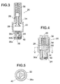
- Figs. 4 and 5 there is shown a third embodiment of a valve device according to the present invention, wherein both valves 34 and 36a are planar, and a radial spacer 42 instead of the stop 32 is fitted in the accumulator 28.
- groove 40 may be formed in the valve 36a instead of the seat 36b. Also, it may be preferable to form an orifice in a wall of the casing 22 which defines the accumulator 28.
- valves 34 and 36a may be either conical, spherical or planar, respectively.
- explosion pressure is rapidly transmitted to the accumulator through the check valve mechanism, and in spite of fluctuation of pressure in the combustion chamber, pressure in the accumulator can be held at an approximately constant value by means of the check valve mechanism.
- pressure in the accumulator is gradually relieved by means of a narrow path.
Landscapes
- Engineering & Computer Science (AREA)
- Mechanical Engineering (AREA)
- General Engineering & Computer Science (AREA)
- Chemical & Material Sciences (AREA)
- Combustion & Propulsion (AREA)
- Valve Device For Special Equipments (AREA)
- Output Control And Ontrol Of Special Type Engine (AREA)
Claims (10)
- Ventileinrichtung (20), welche an einem Zylinder (10) eines Verbrennungsmotors zum zeitweiligen Verbinden eines im Zylinder (10) definierten Brennraums (14) mit der Atmosphäre angebracht ist, umfassend
ein Gehäuse (22) mit einem Durchlaß (30), einem anderen Durchlaß (26) und einer Speicherkammer (28), die durch den einen Durchlaß (30) mit dem Brennraum (14) und durch den anderen Durchlaß (26) mit der Atmosphäre verbunden ist,
eine in dem Gehäuse (22) angeordnete Ventileinrichtung (34, 36) zum Steuern der Verbindung des Brennraums (14) durch den einen Durchlaß (30), die Speicherkammer (28) und den anderen Durchlaß (26) mit der Atmosphäre,
dadurch gekennzeichnet, daß die Ventileinrichtung zwei verschiedene Ventile, ein Rückschlagventil (36) und ein weiteres Ventil (34) umfaßt, die getrennt mit dem einen (30) bzw. dem anderen Durchlaß (26) zusammenwirken, wobei
das Rückschlagventil (36) zulaßt, daß im Brennraum (14) erzeugtes, verdichtetes Gemisch nur in der Richtung von dem Brennraum (14) in die Speicherkammer (28) durch den einen Durchlaß (30) hindurchtritt,
das weitere Ventil (34) den anderen Durchlaß (26) in Reaktion auf den Druck des verdichteten Gemisches in der Speicherkammer (28) schließt,
das weitere Ventil (34) von einer Feder (38) vorgespannt ist, um den anderen Durchlaß (26) zu öffnen, wenn beim Motorstart der Druck innerhalb der Speicherkammer (28) unterhalb eines vorbestimmten Wertes ist, und geeignet ist, den anderen Durchlaß nur dann (26) zu schließen, um den Druck innerhalb der Speicherkammer (28) auf einem im wesentlichen konstanten Wert zu halten, wenn beim Zünden des Motors der Druck des verdichteten Gemisches, welches von dem Brennraum (14) des Motors durch den einen Durchlaß (30) in die Speicherkammer (28) eintritt, in Reaktion auf einen plötzlichen Druckanstieg des verdichteten Gemisches einen vorbestimmten Wert erreicht. - Ventileinrichtung nach Anspruch 1, weiter umfassend einen zusätzlichen Durchlaß (40) in dem Gehäuse (22) zum allmählichen Vermindern des angestiegenen Druckes im verdichteten Gas in der Speicherkammer (28), um dem weiteren Ventil (34) das Öffnen des anderen Durchlasses (26) zu gestatten.
- Ventileinrichtung nach Anspruch 2, wobei der zusätzliche Durchlaß (40) die Speicherkammer (28) mit dem Brennraum (14) verbindet, um das verdichtete Gas in der Speicherkammer (28) in den Brennraum (14) entweichen zu lassen, wenn der Druck innerhalb des Brennraums (14) unter den konstanten Wert abfällt.
- Ventileinrichtung nach Anspruch 3, wobei der zusätzliche Durchlaß (40) im Rückschlagventil (36) vorgesehen ist.
- Ventileinrichtung nach Anspruch 4, wobei das Rückschlagventil (36) ein Ventilelement (36a) und einen Ventilsitz (36b) zum Eingriff mit dem Ventilelement (36a) umfaßt, und der zusätzliche Durchlaß (40) in dem Ventilsitz (36b) ausgebildet ist.
- Ventileinrichtung nach Anspruch 1, wobei der vorbestimmte Wert im wesentlichen der gleiche ist, wie der Druck im Brennraum (14), der beim Zünden des Motors ausgeübt wird.
- Ventileinrichtung nach einem der Ansprüche 1, 4, 5, wobei das Rückschlagventil (36) ein ebenes Ventilelement (36a in Fig. 1) umfaßt.
- Ventileinrichtung nach einem der Ansprüche 1, 4, 5, wobei das Rückschlagventil (36) ein sphärisches bzw. kugelförmiges Ventilelement (36a in Fig. 3) umfaßt.
- Ventileinrichtung nach Anspruch 1, wobei das weitere Ventil ein konisches Ventilelement (34 in Fig. 1) umfaßt.
- Ventileinrichtung nach Anspruch 1, wobei das weitere Ventil ein ebenes Ventilelement (34 in Fig. 4) umfaßt.
Applications Claiming Priority (2)
| Application Number | Priority Date | Filing Date | Title |
|---|---|---|---|
| JP85024/88U | 1988-06-29 | ||
| JP8502488 | 1988-06-29 |
Publications (3)
| Publication Number | Publication Date |
|---|---|
| EP0348924A2 EP0348924A2 (de) | 1990-01-03 |
| EP0348924A3 EP0348924A3 (en) | 1990-12-27 |
| EP0348924B1 true EP0348924B1 (de) | 1995-01-18 |
Family
ID=13847156
Family Applications (1)
| Application Number | Title | Priority Date | Filing Date |
|---|---|---|---|
| EP89111739A Expired - Lifetime EP0348924B1 (de) | 1988-06-29 | 1989-06-28 | Ventileinrichtung |
Country Status (5)
| Country | Link |
|---|---|
| US (1) | US5050546A (de) |
| EP (1) | EP0348924B1 (de) |
| JP (1) | JPH0613845B2 (de) |
| AU (1) | AU615080B2 (de) |
| DE (1) | DE68920643T2 (de) |
Families Citing this family (5)
| Publication number | Priority date | Publication date | Assignee | Title |
|---|---|---|---|---|
| JPH0649911Y2 (ja) * | 1988-09-30 | 1994-12-14 | 小松ゼノア株式会社 | エンジンの始動装置 |
| US5375570A (en) * | 1993-08-31 | 1994-12-27 | Gas Research Institute | Engine compression release |
| SE512975C2 (sv) * | 1998-10-29 | 2000-06-12 | Electrolux Ab | Automatisk dekompressionsventil för förbränningsmotor |
| KR101231482B1 (ko) | 2004-08-19 | 2013-02-07 | 소니 주식회사 | 위치 검출 기구가 설치된 렌즈 경통 및 촬상 장치 |
| CN107989715A (zh) * | 2017-12-28 | 2018-05-04 | 中船动力研究院有限公司 | 中速气体/双燃料发动机的机械式燃气进气阀 |
Family Cites Families (12)
| Publication number | Priority date | Publication date | Assignee | Title |
|---|---|---|---|---|
| DE188464C (de) * | ||||
| AT19567B (de) * | 1904-02-26 | 1905-03-27 | Jacob Christ Hansen-Ellehammer | Selbsttätiges Anlaßventil für Explosionskraftmaschinen. |
| US854035A (en) * | 1904-03-21 | 1907-05-21 | Jacob Christian Hansen-Ellehammer | Starting device for explosion-engines. |
| US1254104A (en) * | 1916-12-26 | 1918-01-22 | Baltimore Oil Engine Company | Relief-valve for internal-combustion engines. |
| US3335711A (en) * | 1965-08-13 | 1967-08-15 | Wisconsin Motor Corp | Easy starting compression release valve |
| US3638632A (en) * | 1970-05-06 | 1972-02-01 | James Willard Boling | Motorcycle compression release |
| US3704988A (en) * | 1970-09-03 | 1972-12-05 | Victa Ltd | Engine decompression device |
| US3782354A (en) * | 1972-05-05 | 1974-01-01 | Walbro Corp | Automatic compression relief valve |
| US3893440A (en) * | 1972-10-26 | 1975-07-08 | Mcculloch Corp | Automatic decompression valve to facilitate starting of an internal combustion engine |
| US3888218A (en) * | 1973-12-26 | 1975-06-10 | Victor Plastics Inc | Compression release for motorcycle engines |
| FR2528931A1 (fr) * | 1982-06-16 | 1983-12-23 | Schmelzer Corp | Valve de commande d'ecoulement |
| US4699096A (en) * | 1985-01-07 | 1987-10-13 | Phillips Howard L | Detonation prevention means for internal combustion engine |
-
1989
- 1989-05-24 JP JP1128635A patent/JPH0613845B2/ja not_active Expired - Lifetime
- 1989-06-27 US US07/371,720 patent/US5050546A/en not_active Expired - Lifetime
- 1989-06-28 AU AU37115/89A patent/AU615080B2/en not_active Ceased
- 1989-06-28 EP EP89111739A patent/EP0348924B1/de not_active Expired - Lifetime
- 1989-06-28 DE DE68920643T patent/DE68920643T2/de not_active Expired - Fee Related
Also Published As
| Publication number | Publication date |
|---|---|
| EP0348924A3 (en) | 1990-12-27 |
| AU3711589A (en) | 1990-01-04 |
| DE68920643D1 (de) | 1995-03-02 |
| DE68920643T2 (de) | 1995-05-18 |
| AU615080B2 (en) | 1991-09-19 |
| JPH02140410A (ja) | 1990-05-30 |
| US5050546A (en) | 1991-09-24 |
| JPH0613845B2 (ja) | 1994-02-23 |
| EP0348924A2 (de) | 1990-01-03 |
Similar Documents
| Publication | Publication Date | Title |
|---|---|---|
| US4781164A (en) | Fuel injection systems for internal combustion engines | |
| US4271796A (en) | Pressure relief system for engine brake | |
| US5398655A (en) | Manifold referenced returnless fuel system | |
| EP0365130B1 (de) | Brennstoffeinspritzdüse | |
| EP0348924B1 (de) | Ventileinrichtung | |
| US2811958A (en) | Pressure-operated valve means for free piston engines | |
| US4905908A (en) | Poppet covered orifice fuel injection nozzle | |
| US4334514A (en) | Fuel injection pump for internal combustion engine | |
| US2722208A (en) | Combined priming pump and pressure regulator | |
| US4384553A (en) | Two stage compression ignition fuel ignitor | |
| US4228774A (en) | Control apparatus for supercharged fuel injection engines | |
| US3370577A (en) | Vacuum control unit | |
| US3788291A (en) | Unitized distributor vacuum spark advance control valve with regulator | |
| US3919991A (en) | Automatic decompression device | |
| EP0361474B1 (de) | Anlasserleichterungsventil für Brennkraftmaschine | |
| US6269795B1 (en) | Fuel injection valve for internal combustion engines | |
| US4993394A (en) | Fuel injection internal combustion engines | |
| US2322606A (en) | Internal combustion engine | |
| US3478729A (en) | Apparatus for controlling ignition time of automobile engine | |
| US2600810A (en) | Engine stop device | |
| US4606317A (en) | Fuel injection system | |
| EP0287242A2 (de) | Hydraulikelement | |
| US2057215A (en) | Carburetor | |
| US2698612A (en) | Automobile engine distributor unit regulator | |
| US4934346A (en) | Sidewall cylinder entrapment valve for internal combustion chamber |
Legal Events
| Date | Code | Title | Description |
|---|---|---|---|
| PUAI | Public reference made under article 153(3) epc to a published international application that has entered the european phase |
Free format text: ORIGINAL CODE: 0009012 |
|
| AK | Designated contracting states |
Kind code of ref document: A2 Designated state(s): DE GB IT SE |
|
| PUAL | Search report despatched |
Free format text: ORIGINAL CODE: 0009013 |
|
| AK | Designated contracting states |
Kind code of ref document: A3 Designated state(s): DE GB IT SE |
|
| 17P | Request for examination filed |
Effective date: 19910423 |
|
| 17Q | First examination report despatched |
Effective date: 19920707 |
|
| GRAA | (expected) grant |
Free format text: ORIGINAL CODE: 0009210 |
|
| AK | Designated contracting states |
Kind code of ref document: B1 Designated state(s): DE GB IT SE |
|
| ITF | It: translation for a ep patent filed | ||
| REF | Corresponds to: |
Ref document number: 68920643 Country of ref document: DE Date of ref document: 19950302 |
|
| PLBE | No opposition filed within time limit |
Free format text: ORIGINAL CODE: 0009261 |
|
| STAA | Information on the status of an ep patent application or granted ep patent |
Free format text: STATUS: NO OPPOSITION FILED WITHIN TIME LIMIT |
|
| 26N | No opposition filed | ||
| REG | Reference to a national code |
Ref country code: GB Ref legal event code: IF02 |
|
| PGFP | Annual fee paid to national office [announced via postgrant information from national office to epo] |
Ref country code: SE Payment date: 20050502 Year of fee payment: 17 |
|
| PGFP | Annual fee paid to national office [announced via postgrant information from national office to epo] |
Ref country code: GB Payment date: 20050516 Year of fee payment: 17 |
|
| PGFP | Annual fee paid to national office [announced via postgrant information from national office to epo] |
Ref country code: DE Payment date: 20050520 Year of fee payment: 17 |
|
| PG25 | Lapsed in a contracting state [announced via postgrant information from national office to epo] |
Ref country code: GB Free format text: LAPSE BECAUSE OF NON-PAYMENT OF DUE FEES Effective date: 20060628 |
|
| PG25 | Lapsed in a contracting state [announced via postgrant information from national office to epo] |
Ref country code: SE Free format text: LAPSE BECAUSE OF NON-PAYMENT OF DUE FEES Effective date: 20060629 |
|
| PGFP | Annual fee paid to national office [announced via postgrant information from national office to epo] |
Ref country code: IT Payment date: 20060630 Year of fee payment: 18 |
|
| PG25 | Lapsed in a contracting state [announced via postgrant information from national office to epo] |
Ref country code: DE Free format text: LAPSE BECAUSE OF NON-PAYMENT OF DUE FEES Effective date: 20070103 |
|
| EUG | Se: european patent has lapsed | ||
| GBPC | Gb: european patent ceased through non-payment of renewal fee |
Effective date: 20060628 |
|
| PG25 | Lapsed in a contracting state [announced via postgrant information from national office to epo] |
Ref country code: IT Free format text: LAPSE BECAUSE OF NON-PAYMENT OF DUE FEES Effective date: 20070628 |