EP0348924A2 - Ventileinrichtung - Google Patents
Ventileinrichtung Download PDFInfo
- Publication number
- EP0348924A2 EP0348924A2 EP89111739A EP89111739A EP0348924A2 EP 0348924 A2 EP0348924 A2 EP 0348924A2 EP 89111739 A EP89111739 A EP 89111739A EP 89111739 A EP89111739 A EP 89111739A EP 0348924 A2 EP0348924 A2 EP 0348924A2
- Authority
- EP
- European Patent Office
- Prior art keywords
- path
- accumulator
- valve
- valve device
- combustion chamber
- Prior art date
- Legal status (The legal status is an assumption and is not a legal conclusion. Google has not performed a legal analysis and makes no representation as to the accuracy of the status listed.)
- Granted
Links
Images

Classifications
-
- F—MECHANICAL ENGINEERING; LIGHTING; HEATING; WEAPONS; BLASTING
- F02—COMBUSTION ENGINES; HOT-GAS OR COMBUSTION-PRODUCT ENGINE PLANTS
- F02D—CONTROLLING COMBUSTION ENGINES
- F02D13/00—Controlling the engine output power by varying inlet or exhaust valve operating characteristics, e.g. timing
- F02D13/02—Controlling the engine output power by varying inlet or exhaust valve operating characteristics, e.g. timing during engine operation
- F02D13/0276—Actuation of an additional valve for a special application, e.g. for decompression, exhaust gas recirculation or cylinder scavenging
-
- F—MECHANICAL ENGINEERING; LIGHTING; HEATING; WEAPONS; BLASTING
- F01—MACHINES OR ENGINES IN GENERAL; ENGINE PLANTS IN GENERAL; STEAM ENGINES
- F01L—CYCLICALLY OPERATING VALVES FOR MACHINES OR ENGINES
- F01L13/00—Modifications of valve-gear to facilitate reversing, braking, starting, changing compression ratio, or other specific operations
- F01L13/08—Modifications of valve-gear to facilitate reversing, braking, starting, changing compression ratio, or other specific operations for decompression, e.g. during starting; for changing compression ratio
-
- F—MECHANICAL ENGINEERING; LIGHTING; HEATING; WEAPONS; BLASTING
- F02—COMBUSTION ENGINES; HOT-GAS OR COMBUSTION-PRODUCT ENGINE PLANTS
- F02N—STARTING OF COMBUSTION ENGINES; STARTING AIDS FOR SUCH ENGINES, NOT OTHERWISE PROVIDED FOR
- F02N19/00—Starting aids for combustion engines, not otherwise provided for
- F02N19/004—Aiding engine start by using decompression means or variable valve actuation
-
- F—MECHANICAL ENGINEERING; LIGHTING; HEATING; WEAPONS; BLASTING
- F02—COMBUSTION ENGINES; HOT-GAS OR COMBUSTION-PRODUCT ENGINE PLANTS
- F02D—CONTROLLING COMBUSTION ENGINES
- F02D13/00—Controlling the engine output power by varying inlet or exhaust valve operating characteristics, e.g. timing
- F02D13/02—Controlling the engine output power by varying inlet or exhaust valve operating characteristics, e.g. timing during engine operation
- F02D2013/0292—Controlling the engine output power by varying inlet or exhaust valve operating characteristics, e.g. timing during engine operation in the start-up phase, e.g. for warming-up cold engine or catalyst
-
- Y—GENERAL TAGGING OF NEW TECHNOLOGICAL DEVELOPMENTS; GENERAL TAGGING OF CROSS-SECTIONAL TECHNOLOGIES SPANNING OVER SEVERAL SECTIONS OF THE IPC; TECHNICAL SUBJECTS COVERED BY FORMER USPC CROSS-REFERENCE ART COLLECTIONS [XRACs] AND DIGESTS
- Y02—TECHNOLOGIES OR APPLICATIONS FOR MITIGATION OR ADAPTATION AGAINST CLIMATE CHANGE
- Y02T—CLIMATE CHANGE MITIGATION TECHNOLOGIES RELATED TO TRANSPORTATION
- Y02T10/00—Road transport of goods or passengers
- Y02T10/10—Internal combustion engine [ICE] based vehicles
- Y02T10/12—Improving ICE efficiencies
Definitions
- the present invention relates to a valve device facilitating start-up of an internal combustion engine by the way of relieving compression pressure in a combustion chamber when the engine is started up.
- a valve device mounted on a cylinder of an internal combustion engine and enabling a combustion chamber defined in the cylinder to communicate with the atmospheric air comprising: a casing having a first path, an accumulator and a second path, the first path communicating the accumulator to the atmospheric air, the second path communicating the accumulator to the combustion chamber when the valve device is mounted on the cylinder; a valve disposed in the accumulator and associated with the first path; a check valve mechanism disposed between the the accumulator and the second communicating path; and a spring biasing the valve in such a direction that the valve does not close between the accumulator and the first path.
- a valve device comprises a third path communicating the accumulator to the outside thereof.
- the spring biases the valve not to close between the accumulator and the first path so that the compression pressure in the combustion chamber which is generated by the piston and is to apply to the starter is relieved into the atmospheric air through in turn the second path, the check valve mechanism, the accumulator and the first path. Therefore, the starter can be driven without any trouble.
- the pressure in the accumulator leaks through the third path so that the valve is forced by the spring to gradually return back to the open condition. As a result, the accumulator communicates again with the atmospheric air through the first path.
- valve device 20 according to the present invention and a spark plug 16 are screwed and mounted on a wall defining a combustion chamber 14 above a piston 12 in a cylinder 10 of a two-cycle engine.
- the valve device 20 has a casing 22 which is secured to the top portion of the cylinder 10 via a washer 18 by the way of engaging a threaded portion 24 formed on the lower portion of the casing 22 with a corresponding threaded portion formed on the cylinder 10.
- a first path 26, an accumulator 28, and a second path 30 are respectively defined such that the accumulator 28 communicates with the atmospheric air and the combustion chamber 14 through the first path 26 and the second path 30, respectively. Also, a stop 32 having notches 32a is fitted in the accumulator 28.
- a first valve 34 is so disposed as to close the first path 26.
- a second valve 36a is so disposed as to close the second path 30.
- This second valve 36a and its seat 36b formed in the accumulator 28 construct a so-called check valve mechanism 36.
- the first and second valves 34 and 36a are conical and planar in shape, respectively.
- a spring 38 is so disposed as to bias the first valve 34 downwardly so that the accumulator 28 normally communicates with the first path 26.
- a narrow groove 40 is formed in the seat 36b so that the check valve mechanism 36 does not completely close between the accumulator 28 and the second path 30.
- valve device 20 when the engine is started up with, for example, a recoil starter (not shown), the valve device 20 is in the condition as shown in Fig. 1.
- fuel-air mixture compressed by the piston 12 enters the accumulator 28 through the second path 30 and the check valve mechanism 36 and is relieved from there through the first path 26 into the atmospheric air, since the first valve 34 is biased not to close between the accumulator 28 and the first path 26 by means of the spring 38.
- counterforce against compression pressure in the combustion chamber 14 does not occur and the engine can be run by the recoil starter without any trouble.
- the pressure in the accumulator 28 leaks into the combustion chamber 14 through the groove 40 and drops so that the first valve 34 is biased by the spring 38 to return back to the condition as shown Fig. 1, namely, in which the first valve 34 does not close between the accumulator 28 and the first path 26.
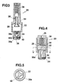
- a check valve mechanism 36 comprises a spherical valve 36a, a seat 36b and a spring 36c.
- FIGs. 4 and 5 there is shown a third embodiment of a valve device according to the present invention, wherein both valves 34 and 36a are planar, and a radial spacer 42 instead of a stop 32 is fitted in an accumulator 28.
- a groove 40 may be formed in a second valve 36a instead of a seat 36b. Also, it may be preferable to form an orifice in a wall of a casing 22 which defines an accumulator 28.
- valves 34 and 36a may be either conical, spherical or planar, respectively.
- explosion pressure is rapidly transmitted to an accumulator through a check valve mechanism, and in spite of fluctuation of pressure in a combustion chamber, pressure in the accumulator can be held at an approximately constant value by means of the check valve mechanism.
- pressure in an accumulator is gradually relieved by means of a narrow path.
Landscapes
- Engineering & Computer Science (AREA)
- Mechanical Engineering (AREA)
- General Engineering & Computer Science (AREA)
- Chemical & Material Sciences (AREA)
- Combustion & Propulsion (AREA)
- Valve Device For Special Equipments (AREA)
- Output Control And Ontrol Of Special Type Engine (AREA)
Applications Claiming Priority (2)
| Application Number | Priority Date | Filing Date | Title |
|---|---|---|---|
| JP85024/88U | 1988-06-29 | ||
| JP8502488 | 1988-06-29 |
Publications (3)
| Publication Number | Publication Date |
|---|---|
| EP0348924A2 true EP0348924A2 (de) | 1990-01-03 |
| EP0348924A3 EP0348924A3 (en) | 1990-12-27 |
| EP0348924B1 EP0348924B1 (de) | 1995-01-18 |
Family
ID=13847156
Family Applications (1)
| Application Number | Title | Priority Date | Filing Date |
|---|---|---|---|
| EP89111739A Expired - Lifetime EP0348924B1 (de) | 1988-06-29 | 1989-06-28 | Ventileinrichtung |
Country Status (5)
| Country | Link |
|---|---|
| US (1) | US5050546A (de) |
| EP (1) | EP0348924B1 (de) |
| JP (1) | JPH0613845B2 (de) |
| AU (1) | AU615080B2 (de) |
| DE (1) | DE68920643T2 (de) |
Cited By (2)
| Publication number | Priority date | Publication date | Assignee | Title |
|---|---|---|---|---|
| US5375570A (en) * | 1993-08-31 | 1994-12-27 | Gas Research Institute | Engine compression release |
| EP0997615A3 (de) * | 1998-10-29 | 2000-08-30 | Ab Electrolux | Automatisches Dekompressionsventil in einer Brennkraftmaschine |
Families Citing this family (3)
| Publication number | Priority date | Publication date | Assignee | Title |
|---|---|---|---|---|
| JPH0649911Y2 (ja) * | 1988-09-30 | 1994-12-14 | 小松ゼノア株式会社 | エンジンの始動装置 |
| KR101231482B1 (ko) | 2004-08-19 | 2013-02-07 | 소니 주식회사 | 위치 검출 기구가 설치된 렌즈 경통 및 촬상 장치 |
| CN107989715A (zh) * | 2017-12-28 | 2018-05-04 | 中船动力研究院有限公司 | 中速气体/双燃料发动机的机械式燃气进气阀 |
Family Cites Families (12)
| Publication number | Priority date | Publication date | Assignee | Title |
|---|---|---|---|---|
| DE188464C (de) * | ||||
| AT19567B (de) * | 1904-02-26 | 1905-03-27 | Jacob Christ Hansen-Ellehammer | Selbsttätiges Anlaßventil für Explosionskraftmaschinen. |
| US854035A (en) * | 1904-03-21 | 1907-05-21 | Jacob Christian Hansen-Ellehammer | Starting device for explosion-engines. |
| US1254104A (en) * | 1916-12-26 | 1918-01-22 | Baltimore Oil Engine Company | Relief-valve for internal-combustion engines. |
| US3335711A (en) * | 1965-08-13 | 1967-08-15 | Wisconsin Motor Corp | Easy starting compression release valve |
| US3638632A (en) * | 1970-05-06 | 1972-02-01 | James Willard Boling | Motorcycle compression release |
| US3704988A (en) * | 1970-09-03 | 1972-12-05 | Victa Ltd | Engine decompression device |
| US3782354A (en) * | 1972-05-05 | 1974-01-01 | Walbro Corp | Automatic compression relief valve |
| US3893440A (en) * | 1972-10-26 | 1975-07-08 | Mcculloch Corp | Automatic decompression valve to facilitate starting of an internal combustion engine |
| US3888218A (en) * | 1973-12-26 | 1975-06-10 | Victor Plastics Inc | Compression release for motorcycle engines |
| FR2528931A1 (fr) * | 1982-06-16 | 1983-12-23 | Schmelzer Corp | Valve de commande d'ecoulement |
| US4699096A (en) * | 1985-01-07 | 1987-10-13 | Phillips Howard L | Detonation prevention means for internal combustion engine |
-
1989
- 1989-05-24 JP JP1128635A patent/JPH0613845B2/ja not_active Expired - Lifetime
- 1989-06-27 US US07/371,720 patent/US5050546A/en not_active Expired - Lifetime
- 1989-06-28 AU AU37115/89A patent/AU615080B2/en not_active Ceased
- 1989-06-28 EP EP89111739A patent/EP0348924B1/de not_active Expired - Lifetime
- 1989-06-28 DE DE68920643T patent/DE68920643T2/de not_active Expired - Fee Related
Cited By (2)
| Publication number | Priority date | Publication date | Assignee | Title |
|---|---|---|---|---|
| US5375570A (en) * | 1993-08-31 | 1994-12-27 | Gas Research Institute | Engine compression release |
| EP0997615A3 (de) * | 1998-10-29 | 2000-08-30 | Ab Electrolux | Automatisches Dekompressionsventil in einer Brennkraftmaschine |
Also Published As
| Publication number | Publication date |
|---|---|
| EP0348924A3 (en) | 1990-12-27 |
| AU3711589A (en) | 1990-01-04 |
| EP0348924B1 (de) | 1995-01-18 |
| DE68920643D1 (de) | 1995-03-02 |
| DE68920643T2 (de) | 1995-05-18 |
| AU615080B2 (en) | 1991-09-19 |
| JPH02140410A (ja) | 1990-05-30 |
| US5050546A (en) | 1991-09-24 |
| JPH0613845B2 (ja) | 1994-02-23 |
Similar Documents
| Publication | Publication Date | Title |
|---|---|---|
| CA1308615C (en) | Fuel injection systems for internal combustion engines | |
| US4692102A (en) | Fuel injection pump for internal combustion engines | |
| EP2047080B1 (de) | Komponenten zum betrieb eines kleinen motors | |
| AU3790995A (en) | Fuel injection device working according to the solid energy accumulator principal, for internal combustion engines | |
| KR880000672A (ko) | 연료 분사형 내연기관 | |
| JPS61112772A (ja) | 燃料噴射系への空気供給装置 | |
| EP0365130B1 (de) | Brennstoffeinspritzdüse | |
| EP0348924A2 (de) | Ventileinrichtung | |
| US4905908A (en) | Poppet covered orifice fuel injection nozzle | |
| US6374782B2 (en) | Air-fuel mixture generating device | |
| US4143632A (en) | Fuel injection timing control device | |
| US2722208A (en) | Combined priming pump and pressure regulator | |
| US4334514A (en) | Fuel injection pump for internal combustion engine | |
| US4384553A (en) | Two stage compression ignition fuel ignitor | |
| EP0361474B1 (de) | Anlasserleichterungsventil für Brennkraftmaschine | |
| US2322606A (en) | Internal combustion engine | |
| US4088102A (en) | Auxiliary acceleration fuel feed device in an internal combustion engine | |
| US4730785A (en) | Fuel injection nozzle for internal combustion engines | |
| US2600810A (en) | Engine stop device | |
| US3707953A (en) | Ignition timing controller for an engine | |
| EP0287242A2 (de) | Hydraulikelement | |
| US4391257A (en) | Fuel injection pump for internal combustion engines | |
| US3386647A (en) | Free-piston engine diaphragm compressor | |
| US3446197A (en) | Ignition system for free-piston engine | |
| US5700402A (en) | Crankcase fuel injection system for two-cycle internal combustion engines |
Legal Events
| Date | Code | Title | Description |
|---|---|---|---|
| PUAI | Public reference made under article 153(3) epc to a published international application that has entered the european phase |
Free format text: ORIGINAL CODE: 0009012 |
|
| AK | Designated contracting states |
Kind code of ref document: A2 Designated state(s): DE GB IT SE |
|
| PUAL | Search report despatched |
Free format text: ORIGINAL CODE: 0009013 |
|
| AK | Designated contracting states |
Kind code of ref document: A3 Designated state(s): DE GB IT SE |
|
| 17P | Request for examination filed |
Effective date: 19910423 |
|
| 17Q | First examination report despatched |
Effective date: 19920707 |
|
| GRAA | (expected) grant |
Free format text: ORIGINAL CODE: 0009210 |
|
| AK | Designated contracting states |
Kind code of ref document: B1 Designated state(s): DE GB IT SE |
|
| ITF | It: translation for a ep patent filed | ||
| REF | Corresponds to: |
Ref document number: 68920643 Country of ref document: DE Date of ref document: 19950302 |
|
| PLBE | No opposition filed within time limit |
Free format text: ORIGINAL CODE: 0009261 |
|
| STAA | Information on the status of an ep patent application or granted ep patent |
Free format text: STATUS: NO OPPOSITION FILED WITHIN TIME LIMIT |
|
| 26N | No opposition filed | ||
| REG | Reference to a national code |
Ref country code: GB Ref legal event code: IF02 |
|
| PGFP | Annual fee paid to national office [announced via postgrant information from national office to epo] |
Ref country code: SE Payment date: 20050502 Year of fee payment: 17 |
|
| PGFP | Annual fee paid to national office [announced via postgrant information from national office to epo] |
Ref country code: GB Payment date: 20050516 Year of fee payment: 17 |
|
| PGFP | Annual fee paid to national office [announced via postgrant information from national office to epo] |
Ref country code: DE Payment date: 20050520 Year of fee payment: 17 |
|
| PG25 | Lapsed in a contracting state [announced via postgrant information from national office to epo] |
Ref country code: GB Free format text: LAPSE BECAUSE OF NON-PAYMENT OF DUE FEES Effective date: 20060628 |
|
| PG25 | Lapsed in a contracting state [announced via postgrant information from national office to epo] |
Ref country code: SE Free format text: LAPSE BECAUSE OF NON-PAYMENT OF DUE FEES Effective date: 20060629 |
|
| PGFP | Annual fee paid to national office [announced via postgrant information from national office to epo] |
Ref country code: IT Payment date: 20060630 Year of fee payment: 18 |
|
| PG25 | Lapsed in a contracting state [announced via postgrant information from national office to epo] |
Ref country code: DE Free format text: LAPSE BECAUSE OF NON-PAYMENT OF DUE FEES Effective date: 20070103 |
|
| EUG | Se: european patent has lapsed | ||
| GBPC | Gb: european patent ceased through non-payment of renewal fee |
Effective date: 20060628 |
|
| PG25 | Lapsed in a contracting state [announced via postgrant information from national office to epo] |
Ref country code: IT Free format text: LAPSE BECAUSE OF NON-PAYMENT OF DUE FEES Effective date: 20070628 |