EP0348920A2 - Procédé et circuit de surveillance de canalisations, en particulier pour détecter les fuites d'une canalisation de chauffage - Google Patents
Procédé et circuit de surveillance de canalisations, en particulier pour détecter les fuites d'une canalisation de chauffage Download PDFInfo
- Publication number
- EP0348920A2 EP0348920A2 EP89111720A EP89111720A EP0348920A2 EP 0348920 A2 EP0348920 A2 EP 0348920A2 EP 89111720 A EP89111720 A EP 89111720A EP 89111720 A EP89111720 A EP 89111720A EP 0348920 A2 EP0348920 A2 EP 0348920A2
- Authority
- EP
- European Patent Office
- Prior art keywords
- circuit
- measuring
- short
- circuit according
- circuited
- Prior art date
- Legal status (The legal status is an assumption and is not a legal conclusion. Google has not performed a legal analysis and makes no representation as to the accuracy of the status listed.)
- Granted
Links
Images

Classifications
-
- G—PHYSICS
- G01—MEASURING; TESTING
- G01M—TESTING STATIC OR DYNAMIC BALANCE OF MACHINES OR STRUCTURES; TESTING OF STRUCTURES OR APPARATUS, NOT OTHERWISE PROVIDED FOR
- G01M3/00—Investigating fluid-tightness of structures
- G01M3/02—Investigating fluid-tightness of structures by using fluid or vacuum
- G01M3/04—Investigating fluid-tightness of structures by using fluid or vacuum by detecting the presence of fluid at the leakage point
- G01M3/16—Investigating fluid-tightness of structures by using fluid or vacuum by detecting the presence of fluid at the leakage point using electric detection means
- G01M3/18—Investigating fluid-tightness of structures by using fluid or vacuum by detecting the presence of fluid at the leakage point using electric detection means for pipes, cables or tubes; for pipe joints or seals; for valves; for welds; for containers, e.g. radiators
Definitions
- the invention relates to a method for monitoring pipes, in particular district heating pipes for leaks, currents being sent through monitoring circuits, preferably with rectifier diodes and indicators, the resistance of which changes when moisture occurs.
- the lines are made fully insulated and the sensor is provided with a large area at certain points in order to then achieve a strong reaction to the moisture when the desired point is reached.
- the sensor was enclosed in polyurethane foam, so that small amounts of moisture could be chemically bound in the foam on the end faces of the pipe insulation.
- the measuring circuit and the sensor system were kept electrically isolated, i. H. a connection, for example, to the pipe potential was avoided in order to enable a kind of "potential-free" measurement, in order to be independent of other voltage influences.
- the invention is therefore based on the object of making available a method which enables pipes to be monitored without faults due to short-circuits on the indicators, a high sensitivity to moisture still being ensured and an application to cables which have already been laid is possible.
- the invention is based on the knowledge that the corrosion of the materials causing the short circuits is caused by the occurrence of inductively or capacitively coupled stray currents and that the measuring circuit is not “potential-free” as desired and expected. Accordingly, the invention proposes for the method of the type mentioned that the monitoring circuits are short-circuited to avoid uncontrollable corrosion caused by stray currents in order to prevent the formation of an electrical potential by stray currents.
- two wires or one wire is short-circuited to the transport tube in order to carry out the method at a locally advantageous location.
- the measuring circuit is equipped with a resistor and a rectifier diode at one end of the measuring section, it is advantageously provided that the wires are short-circuited at the end of the measuring section opposite the resistor and the rectifier diode.
- the short circuit can expediently be effected by a capacitor as a bridge, or the capacitor is connected in parallel to the rectifier diode.
- the ends of the measuring section sections are advantageously short-circuited.
- the invention proposes that a measuring device is provided at the measuring end of the measuring section which cancels the short circuit during the measuring process.
- the measuring device includes measuring electronics with its own battery.
- Another embodiment of the invention provides that the stray current bridge switch also creates a short circuit during the measuring process and the measurement is carried out against the pipe to be monitored. The bridge switch is then only opened to measure the line continuity.
- the identification of a wire break in the monitoring circuit is achieved with resistances between forward and reverse.
- the invention avoids premature failure of the indicators and the need to replace the indicators, which means that the lines have to be dug up.
- the invention can be used universally and causes little cost.
- the notification threshold can be lowered very far in the measures according to the invention.
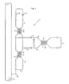
- FIG. 1 shows a measuring circuit 1 with the two measuring section sections A and B. Further measuring section sections can be provided which form so-called line hierarchies through the corresponding diode circuits and the breakdown voltages thus required.
- the measuring section A of the measuring circuit 1 the associated district heating pipe 2 is shown, which is to be monitored for leakage.
- the indicators 3 consist of oppositely arranged metal plates 4, between which a foam 5 is arranged. If there is a leak in the district heating pipeline 2, the moisture in the foam 5 increases and a short circuit is generated between the plates 4 of the indicators 3.
- jumper plugs 7 are provided at the ends of the measuring section.
- the bridge switch 7 is provided at the end of the measuring section opposite the resistor 8 and the rectifier diode 9 in order to short-circuit them.
- resistors 13 are arranged in the measuring circuit between the forward 10 and the return 11 in order to be able to recognize a break in the network.
- a measuring device 14 is provided at the measuring end of the measuring section, to which measuring bridge switches 15 are assigned. With these measuring bridge switches 15, the short circuit is canceled by the measuring device 14 during the measuring process.
- the measuring device 14 contains measuring electronics, not shown in detail, with its own battery.
- the measuring bridge switch 15 can be dispensed with and the measurement can be carried out against the district heating pipeline 2 to be monitored, as shown by the dashed wire 16 in FIG. 1.
- the circuit according to the invention can be used both in isolated measuring circuits and in a measurement against the district heating pipe to be monitored. In addition to the use in new installations, it also presents relatively minor difficulties in converting existing measuring circuits according to the invention.
- the measures according to the invention also avoid the risk of undefined stray currents which would otherwise arise in the measuring circuit with the diodes 9 in that the diode 9 limits the current flow to its breakdown voltage in one direction, while a potential was present in the other direction , which could have a corrosive effect on indicators 3.
Landscapes
- Physics & Mathematics (AREA)
- General Physics & Mathematics (AREA)
- Examining Or Testing Airtightness (AREA)
- Investigating Or Analyzing Materials By The Use Of Electric Means (AREA)
Priority Applications (1)
| Application Number | Priority Date | Filing Date | Title |
|---|---|---|---|
| AT89111720T ATE94645T1 (de) | 1988-06-30 | 1989-06-28 | Verfahren und schaltung zur ueberwachung von rohren, insbesondere von fernheizrohrleitungen auf leckage. |
Applications Claiming Priority (2)
| Application Number | Priority Date | Filing Date | Title |
|---|---|---|---|
| DE3822123 | 1988-06-30 | ||
| DE3822123A DE3822123C1 (fr) | 1988-06-30 | 1988-06-30 |
Publications (3)
| Publication Number | Publication Date |
|---|---|
| EP0348920A2 true EP0348920A2 (fr) | 1990-01-03 |
| EP0348920A3 EP0348920A3 (en) | 1990-05-30 |
| EP0348920B1 EP0348920B1 (fr) | 1993-09-15 |
Family
ID=6357645
Family Applications (1)
| Application Number | Title | Priority Date | Filing Date |
|---|---|---|---|
| EP89111720A Expired - Lifetime EP0348920B1 (fr) | 1988-06-30 | 1989-06-28 | Procédé et circuit de surveillance de canalisations, en particulier pour détecter les fuites d'une canalisation de chauffage |
Country Status (3)
| Country | Link |
|---|---|
| EP (1) | EP0348920B1 (fr) |
| AT (1) | ATE94645T1 (fr) |
| DE (2) | DE3822123C1 (fr) |
Cited By (1)
| Publication number | Priority date | Publication date | Assignee | Title |
|---|---|---|---|---|
| DE102008014801A1 (de) | 2008-03-09 | 2009-09-10 | Hidde, Axel R., Dr. Ing. | Leckageüberwachung bei zylindrischen Anordnungen |
Family Cites Families (6)
| Publication number | Priority date | Publication date | Assignee | Title |
|---|---|---|---|---|
| DE1222164B (de) * | 1964-04-30 | 1966-08-04 | Siemens Ag | Schaltung zum Pruefen des Meldeleiterpaares eines kunststoffummantelten elektrischen Kabels oder einer solchen Leitung auf Unterbrechung |
| DE2337983C2 (de) * | 1973-07-26 | 1984-03-22 | Bernd 6271 Limbach Brandes | Ortungs- und Überwachungsschaltung |
| DE2458055A1 (de) * | 1974-12-07 | 1976-06-16 | Kabel Metallwerke Ghh | Verfahren zur ueberwachung von metallischen leitungsrohren |
| DE2725225A1 (de) * | 1977-06-03 | 1978-12-07 | Detlef Saft | Durchmesser-praezisionsreibeisen |
| AT370229B (de) * | 1981-07-16 | 1983-03-10 | Egger K Kunststoffwerk | Schaltungsanordnung zur bestimmung von leckstellen in isolierten rohrleitungen |
| WO1986005880A1 (fr) * | 1985-04-01 | 1986-10-09 | Wilfried Schoeps | Senseurs electriques de detection de fuites dans des systemes de canalisations |
-
1988
- 1988-06-30 DE DE3822123A patent/DE3822123C1/de not_active Expired - Lifetime
-
1989
- 1989-06-28 AT AT89111720T patent/ATE94645T1/de not_active IP Right Cessation
- 1989-06-28 EP EP89111720A patent/EP0348920B1/fr not_active Expired - Lifetime
- 1989-06-28 DE DE89111720T patent/DE58905594D1/de not_active Expired - Fee Related
Cited By (1)
| Publication number | Priority date | Publication date | Assignee | Title |
|---|---|---|---|---|
| DE102008014801A1 (de) | 2008-03-09 | 2009-09-10 | Hidde, Axel R., Dr. Ing. | Leckageüberwachung bei zylindrischen Anordnungen |
Also Published As
| Publication number | Publication date |
|---|---|
| DE58905594D1 (de) | 1993-10-21 |
| DE3822123C1 (fr) | 1990-03-15 |
| EP0348920A3 (en) | 1990-05-30 |
| EP0348920B1 (fr) | 1993-09-15 |
| ATE94645T1 (de) | 1993-10-15 |
Similar Documents
| Publication | Publication Date | Title |
|---|---|---|
| AT501758B1 (de) | Verfahren zur ortung von leckagen in rohren | |
| DE69022282T2 (de) | Vorrichtung zur Anzeige übermässiger Quetschung einer Kabelanordnung gegen eine elektrisch geerdete Struktur. | |
| CH657438A5 (de) | Flexibles leitungsrohr. | |
| DE19819219C1 (de) | Verfahren und Vorrichtung zur Überwachung einer Elektrodenleitung einer bipolaren Hochstpannungs-Gleichstrom-Übertragungs-Anlage | |
| DE2306465A1 (de) | Vorrichtung zum nachweisen des vorhandenseins und der lage von leckstellen bei oelleitungen | |
| DE3930530A1 (de) | Leckueberwachungseinrichtung fuer rohrleitungen | |
| DE2340845A1 (de) | Kapazitaetsmessvorrichtung | |
| DE2337983C2 (de) | Ortungs- und Überwachungsschaltung | |
| DE19521018C2 (de) | Rohrleitungssystem, insbesondere für die Übertragung von Fernwärme | |
| DE102018202010A1 (de) | Verfahren zur Vorhersage einer bevorstehenden Beschädigung einer Verbindungsstelle zwischen zwei elektrischen Leitern in einem Kraftfahrzeugbordnetz, Vorrichtung und Kraftfahrzeug | |
| DE3225742A1 (de) | Schaltungsanordnung zur bestimmung von leckstellen isolierten rohrleitungen | |
| DE2322085A1 (de) | Fluidgefuelltes elektrisches kabel | |
| DE19527972B4 (de) | Messschaltung unter Verwendung eines Messfühlers zum Erfassen und Orten von Wassereinbrüchen | |
| EP0348920A2 (fr) | Procédé et circuit de surveillance de canalisations, en particulier pour détecter les fuites d'une canalisation de chauffage | |
| EP0307615A2 (fr) | Dispositif pour la détermination non destructive de dégâts dans la couverture de ponts, réservoirs et toits plats | |
| DE1814857A1 (de) | Anordnung zur Signalisierung von Leckstellen in einer Rohrleitung zum Fluessigkeitstransport | |
| DE1909661A1 (de) | Messanordnung zur Feststellung von abnormalen zustaenden in elektrischen Heizvorrichtungen | |
| DE19914658C2 (de) | Anordnung zur Messung von Undichtigkeiten in Abdichtungssystemen zur Leckagedetektion und Leckageortung elektrisch leitender Fluide sowie Verwendung einer solchen Anordnung | |
| DE10258417B3 (de) | Verfahren und Schaltungsanordnung zum Erfassen und/oder Bestimmen der Beschaffenheit eines Mediums | |
| DE19817940C2 (de) | Anordnung, Verfahren und Strommeßeinrichtung zum Messen eines Stromes in einem Leiter | |
| EP3567389A1 (fr) | Procédé de surveillance continue de l'isolation d'un agencement conducteur électrique | |
| DE19515068A1 (de) | Anordnung zur TE-Detektion in Hochspannungskabeln und in deren Verbindungselementen | |
| DE10257330A1 (de) | Messverfahren zur Früherkennung von eingedrungener Flüssigkeit in lang gestreckten Betriebsmitteln | |
| EP0839325B1 (fr) | Montage de mesure pour la detection et la localisation d'entrees d'eau dans des tuyaux ou des cables | |
| EP1728895A1 (fr) | Méthode de surveillance pour détecter l'approche d'un corps conductive au pipe-line pour fluides cathodiquement protégée |
Legal Events
| Date | Code | Title | Description |
|---|---|---|---|
| PUAI | Public reference made under article 153(3) epc to a published international application that has entered the european phase |
Free format text: ORIGINAL CODE: 0009012 |
|
| AK | Designated contracting states |
Kind code of ref document: A2 Designated state(s): AT BE CH DE ES FR GB GR IT LI LU NL SE |
|
| PUAL | Search report despatched |
Free format text: ORIGINAL CODE: 0009013 |
|
| AK | Designated contracting states |
Kind code of ref document: A3 Designated state(s): AT BE CH DE ES FR GB GR IT LI LU NL SE |
|
| 17P | Request for examination filed |
Effective date: 19900521 |
|
| 17Q | First examination report despatched |
Effective date: 19910523 |
|
| GRAA | (expected) grant |
Free format text: ORIGINAL CODE: 0009210 |
|
| AK | Designated contracting states |
Kind code of ref document: B1 Designated state(s): AT BE CH DE ES FR GB GR IT LI LU NL SE |
|
| PG25 | Lapsed in a contracting state [announced via postgrant information from national office to epo] |
Ref country code: IT Free format text: LAPSE BECAUSE OF FAILURE TO SUBMIT A TRANSLATION OF THE DESCRIPTION OR TO PAY THE FEE WITHIN THE PRE;WARNING: LAPSES OF ITALIAN PATENTS WITH EFFECTIVE DATE BEFORE 2007 MAY HAVE OCCURRED AT ANY TIME BEFORE 2007. THE CORRECT EFFECTIVE DATE MAY BE DIFFERENT FROM THE ONE RECORDED.SCRIBED TIME-LIMIT Effective date: 19930915 Ref country code: GR Free format text: LAPSE BECAUSE OF FAILURE TO SUBMIT A TRANSLATION OF THE DESCRIPTION OR TO PAY THE FEE WITHIN THE PRESCRIBED TIME-LIMIT Effective date: 19930915 Ref country code: GB Effective date: 19930915 Ref country code: BE Effective date: 19930915 Ref country code: FR Effective date: 19930915 Ref country code: SE Effective date: 19930915 Ref country code: ES Free format text: THE PATENT HAS BEEN ANNULLED BY A DECISION OF A NATIONAL AUTHORITY Effective date: 19930915 Ref country code: NL Effective date: 19930915 |
|
| REF | Corresponds to: |
Ref document number: 94645 Country of ref document: AT Date of ref document: 19931015 Kind code of ref document: T |
|
| REF | Corresponds to: |
Ref document number: 58905594 Country of ref document: DE Date of ref document: 19931021 |
|
| EN | Fr: translation not filed | ||
| NLV1 | Nl: lapsed or annulled due to failure to fulfill the requirements of art. 29p and 29m of the patents act | ||
| GBV | Gb: ep patent (uk) treated as always having been void in accordance with gb section 77(7)/1977 [no translation filed] |
Effective date: 19930915 |
|
| PG25 | Lapsed in a contracting state [announced via postgrant information from national office to epo] |
Ref country code: AT Effective date: 19940628 |
|
| PG25 | Lapsed in a contracting state [announced via postgrant information from national office to epo] |
Ref country code: CH Effective date: 19940630 Ref country code: LU Free format text: LAPSE BECAUSE OF NON-PAYMENT OF DUE FEES Effective date: 19940630 Ref country code: LI Effective date: 19940630 |
|
| PLBE | No opposition filed within time limit |
Free format text: ORIGINAL CODE: 0009261 |
|
| STAA | Information on the status of an ep patent application or granted ep patent |
Free format text: STATUS: NO OPPOSITION FILED WITHIN TIME LIMIT |
|
| 26N | No opposition filed | ||
| REG | Reference to a national code |
Ref country code: CH Ref legal event code: PL |
|
| PGFP | Annual fee paid to national office [announced via postgrant information from national office to epo] |
Ref country code: DE Payment date: 20050421 Year of fee payment: 17 |
|
| PG25 | Lapsed in a contracting state [announced via postgrant information from national office to epo] |
Ref country code: DE Free format text: LAPSE BECAUSE OF NON-PAYMENT OF DUE FEES Effective date: 20070103 |