EP0348510A1 - Selbstangetriebene steinbrechvorrichtung - Google Patents
Selbstangetriebene steinbrechvorrichtung Download PDFInfo
- Publication number
- EP0348510A1 EP0348510A1 EP19880909118 EP88909118A EP0348510A1 EP 0348510 A1 EP0348510 A1 EP 0348510A1 EP 19880909118 EP19880909118 EP 19880909118 EP 88909118 A EP88909118 A EP 88909118A EP 0348510 A1 EP0348510 A1 EP 0348510A1
- Authority
- EP
- European Patent Office
- Prior art keywords
- cover member
- plate
- crusher
- stone
- stone crusher
- Prior art date
- Legal status (The legal status is an assumption and is not a legal conclusion. Google has not performed a legal analysis and makes no representation as to the accuracy of the status listed.)
- Ceased
Links
- 239000004575 stone Substances 0.000 title claims abstract description 116
- 238000010276 construction Methods 0.000 claims description 11
- 230000006835 compression Effects 0.000 claims description 6
- 238000007906 compression Methods 0.000 claims description 6
- 230000002093 peripheral effect Effects 0.000 claims description 4
- 239000003981 vehicle Substances 0.000 description 34
- 239000002245 particle Substances 0.000 description 4
- 230000008093 supporting effect Effects 0.000 description 4
- XEEYBQQBJWHFJM-UHFFFAOYSA-N Iron Chemical compound [Fe] XEEYBQQBJWHFJM-UHFFFAOYSA-N 0.000 description 2
- 238000007792 addition Methods 0.000 description 2
- 238000010008 shearing Methods 0.000 description 2
- 241001052209 Cylinder Species 0.000 description 1
- 238000009412 basement excavation Methods 0.000 description 1
- 230000005540 biological transmission Effects 0.000 description 1
- 230000000875 corresponding effect Effects 0.000 description 1
- 230000001186 cumulative effect Effects 0.000 description 1
- 238000013016 damping Methods 0.000 description 1
- 239000003337 fertilizer Substances 0.000 description 1
- 239000008187 granular material Substances 0.000 description 1
- 229910052742 iron Inorganic materials 0.000 description 1
- 230000035515 penetration Effects 0.000 description 1
- 229920000136 polysorbate Polymers 0.000 description 1
Images


Classifications
-
- E—FIXED CONSTRUCTIONS
- E02—HYDRAULIC ENGINEERING; FOUNDATIONS; SOIL SHIFTING
- E02F—DREDGING; SOIL-SHIFTING
- E02F5/00—Dredgers or soil-shifting machines for special purposes
-
- E—FIXED CONSTRUCTIONS
- E02—HYDRAULIC ENGINEERING; FOUNDATIONS; SOIL SHIFTING
- E02F—DREDGING; SOIL-SHIFTING
- E02F5/00—Dredgers or soil-shifting machines for special purposes
- E02F5/30—Auxiliary apparatus, e.g. for thawing, cracking, blowing-up, or other preparatory treatment of the soil
- E02F5/305—Arrangements for breaking-up hard ground
Definitions
- the present invention relates to a self-propelled stone crusher for crushing dispersed stones on and under ground during leveling operation of agricultural ground and the like, and more particularly to a self-propelled stone crusher so constructed as to: be operated even on the soft ground without lowering its traveling performance; remove by itself such a large stone that can not be crushed therewith; and crush stones as it excavates the superficial earth of the ground.
- the self-propelled stone crusher of the present invention also performs the function of leveling the ground after stones are crushed.
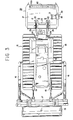
- a conventional self-propelled stone crusher such as one made by Willy Bald Co., West Germany, which one is provided with a crusher 2 in its rear end portion with respect to a traveling direction of its wheel type vehicle 1 which pulls the crusher 2 in operation to enable the crusher 2 to crush stones dispersed on and under the ground of agricultural field and the like up to a predetermined depth of the ground.
- the crusher 2 is constructed of: an excavator 3 for picking up the stones; and a hammer rotor 4 for hitting the thus picked up stones at a headlong speed to crush the same.
- the hammer rotor 4 directly hit large stones dispersed on the ground as it moves downward.
- large crushing reaction is produced in the hammer rotor 4 at this time, which reaction must be borne on a rotary shaft 5 of the hammer rotor 4.
- the rotary shaft 5 must be firmly mounted in the crusher 2.
- large stones must be removed manually or by the use of stone picker, which cuts down efficiency in stone crushing operation or work of the crusher 2.
- penetration depth of the excavator 3 of the crusher 2 is relatively small to make it difficult for the crusher 2 to crush stones having covered with a relatively thick superficial earth of the ground.
- the crusher 2 since only rotational motion of the hammer rotor 4 contributes to stone- crushing operation or work of the crusher 2, the crusher 2 is relatively poor in stone-crushing efficiency.
- a self-propelled stone crusher vehicle comprising: a blade so mounted on a front portion of a vehicle body of the crusher vehicle as to be vertically movable, the vehicle body being provided with a crawler type traveling portion; and a stone crusher detachably mounted on a rear-end portion of the vehicle body with respect to a traveling direction of the vehicle body so as to be vertically movable.
- the self-propelled stone crusher vehicle as set forth in the above first embodiment, wherein: the stone crusher further comprises a sheet of ground leveling means mounted on its rear-end portion.
- a stone crusher comprising: a cover member so detachably connected to a rear-end portion of a crawler type construction vehicle through a connecting means as to be vertically movable; a rotary drum which is rotatably mounted on opposite-side portions of the cover member while detachably provided with a plurality of bits in its outer peripheral surface; repulsive plate means which cooperate with the rotary drum to perform the function of crushing stones, the repulsive plate means being so disposed in an inner surface of the cover member as to be spaced apart from each other and as to be sequentially fixed to the inner surface of the cover member in a rotational direction of the rotary drum; a granulating plate means; a sorter means; and a rotary-drum driving mechanism mounted on an outside of the cover member.
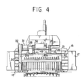
- a track frame 11 is mounted on each of opposite sides of a vehicle body 10 of a crawler type construction vehicle "A".
- a crawler track 14 runs round an idler wheel 12 and a sprocket wheel 13. These wheels 12 and 13 are disposed in a front and a rear portion of the track frame 11.
- a crawler type traveling portion 15 of the construction vehicle “A” has the above construction in which the sprocket wheel 13 is connected to an engine (not shown) through suitable transmission gears (not shown) such as a final reduction gear, a steering clutch/brake unit, a speed-change gear and a torque converter.
- a blade arm 16 is so connected to the track frame 11 as to be vertically swingable.
- a blade 17 is pivotally mounted on a front end of the blade arm 16.
- a lift cylinder 18 is so interposed between the blade 17 and a vehicle body 10 as to be rotatably connected therewith.
- a fertilizer distributer 19 is detachably mounted on the blade 17.
- the reference numeral 20 denotes a stone crusher which is so detachably mounted on a rear end of the vehicle "A" as to be vertically swingable.
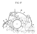
- the stone crusher 20 is provided with a cover member 21 which opens to the ground.
- a bracket 23 is detachably mounted on the cover member 21 by means of bolts 22.
- another bracket 24 is mounted on a rear portion of the vehicle body 10.
- Both of a link 25 and a cylinder 26 are so interposed between theses brackets 23 and 24 as to be rotatable relative to them to enable the bracket 23 to vertically swing.
- a rotary drum 27 made of iron.
- a plurality of bit-mounting base members 28 are so fixedly mounted on an outer peripheral surface of the rotary drum 27 as to be spaced apart from each other in both of a circumferential and an axial direction of the rotary drum 27.
- a conical bit 29 is detachably mounted on each of these bit-mounting base members 28.
- the rotary drum 27 is connected to a motor 31 through a rotary-drum driving mechanism 30.
- the above rotary-drum driving mechanism 30 is provided with a case 32 which is mounted on one of the opposite side plates 21a, 21a of the cover member 21.
- the motor 31 is fixedly mounted on an upper portion of the case 32.
- a power-output shaft 31a of this motor 31 is connected to a rotary-drum driving shaft 36 through an upper sprocket wheel 33, chain 34 and a lower sprocket wheel 35. Consequently, the rotary drum 27 is rotatably driven by the motor 31 in the direction of the arrow shown in each of Figs. 5 and 8.
- a repulsive plate unit 40 sequentially mounted in an inner wall of the cover member 21 are : a repulsive plate unit 40, a granulating plate unit 41 and a sorter mechanism 42 so as to be spaced apart from each other in a rotational direction of the rotary drum 27, whereby these components cooperate with the rotary drum 27 to perform the function of crushing stones.
- a cover plate 43 is mounted on a rear portion of the cover member 21.
- a base plate 40c is inclined upward relative to the ground (so as to be parallel to the cover member 21).
- a plurality of bits 40d are so fixedly mounted on the base plate 40 as to be directed toward the ground.
- the number of the repulsive plate unit 40 shown in Fig. 5 is plural and arranged in a front portion of the inner surface of the cover member 21 with respect to the traveling direction of the vehicle "A".
- Each of such repulsive plate units 40 is provided with: a mounting plate 44 which is so mounted on the inner surface of the cover member 21 through a plurality of bolts/nuts 46 as to be movable along the inner surface of the cover member 21 over a predetermined wide range in the traveling direction of the vehicle "A" or in a direction counter to the traveling direction; and a repulsive plate 40a a base end of which is fixed to the mounting plate 44 through a longitudinal plate 45 to enable the repulsive plate 40a to be oppositely disposed from a path of each of the bits 29 through a suitable clearance.
- the above-mentioned predetermined wide range of adjustable distance of the mounting plate 44 depends on a longitudinal diameter of an elongated hole 44a of the mounting plate 44, in which elongated hole 44a is inserted a bolt of the bolts/nuts 46.
- the repulsive plate 44a is provided with a plurality of concave portions 40b in its front-end surface which is oppositely disposed from the rotary drum 27.
- a base-end portion of the granulating plate 41a is rotatably mounted on the inner surface of the cover member 21 through a pin 48.
- a lever element 49 is so provided as to be vertically movably supported by the cover member 21, a lower end of the lever element 49 being connected to a front-end portion of the granulating plate 41a.
- the lever element 49 is mounted on an outer surface of the cover member 21, and extends into the interior of a sleeve element 50 a bottom of which is opened so that an upper-end screw portion 49a of the lever element 49 extends outward from the bottom opening of the sleeve element 50, whereby the upper-end screw portion 49a of the lever element 49 is threadably engaged with a nut 51.
- the lever element 49 is resiliently urged downward under the influence of a compression spring 52 which is interposed between the inner surface of the sleeve element 50 and a large-diameter portion 49b provided in an intermediate portion of the lever element 49.
- the above-mentioned sorter mechanism 42 is provided with a plurality of longitudinal levers 42a which are so arranged as to be spaced apart from each other in a direction perpendicular to the traveling direction of the vehicle "A".
- the bits 29 of the rotary drum 27 crush stones dispersed in the ground. At this time, some of the stones dispersed under the ground are picked up on the ground by the bits 29 as the rotary drum 27 rotates.
- the stones picked up by the bits 29 fixedly mounted on the outer peripheral surface of the rotary drum 27 are prevented from being scattered so that the stones are repeatedly subjected to the shearing/compression forces and impacts caused by the bits 29 and the repulsive plates 40a, whereby the stones are efficiently crushed.
- the granulating plate 41a is substantially horizontally mounted substantially immediately on the rotary drum 27 so as to increase a space between itself and the the repulsive plates 40a to the maximum extent.
- the granulating plate 41a so directs the stones having collided against it as to hit again the bits 29 of the rotary drum 27.
- the front end of the granulating plate 41a which front end is oppositely disposed from the rotary drum 27, is curved downward so as to make it complicated to pass the stones, whereby the number of collisions of the stones between the bits 29 and the stones are increased.
- the granulating plate 41 When the lever element 49 is rotated, the granulating plate 41 is vertically swung on the pin 48 provided in its base-end portion to make it possible to adjust the clearances between the paths of the bits 29 of the rotary drum 27 and the front end of the granulating plate 41a according to an amount of the stones being crushed.
- the granulating plate 41a since the lever element 49 is urged downward under the influence of the compression spring 52, the granulating plate 41a performs the function of damping the impacts of the stones when it is hit by the stones.
- the granulating plate 41a may be vertically swung by means of a suitable cylinder (not shown).
- the thus granulated stones pass rearward through the longitudinal levers 42a, 42a which constitute the sorter mechanism 42 in which the longitudinal levers 42a, 42a are spaced apart from each other at predetermined intervals.
- the stones which can not pass through the sorter mechanism 42 collide against the longitudinal levers 42a, 42a so as to be rebounded toward the bits 29 of the rotary drum 27.
- the thus rebounded stones are hit again by the bits 29 while buried under the ground by the bits 29.
- a ground leveling plate 53 is mounted on a rear end of the cover member 21 of the stone crusher 20.
- the rear portion cover plate 43 of the stone crusher 20 is vertically swingably mounted on the pin 54 through a bracket.
- Other brackets 55, 55 are fixed to opposite sides of the cover plate 43.
- the ground leveling plate 53 is vertically swingably mounted through a supporting axle 56.
- a pair of levers 57, 57 each of which extends in the traveling direction of the vehicle "A" along the side portion of the cover plate 43 so as to be disposed at a substantially right angle relative to a pendulous portion of the ground leveling plate 53.
- each of the levers 57 In a position corresponding to an upper position of a front end of each of the levers 57, 57 is extended a front end of each of rods 58 which are fixedly mounted on opposite side portions of an upper surface of the cover plate 43.
- These rods 58, 58 are connected with the above levers 57, 57 through springs 59, 59 which keep the pendulous portion of the ground leveling plate 53 vertical.
- the ground leveling plate 53 is rotated on the supporting axle 56 so as to be swung upward ( i.e., so as to be rotated counterclockwise in Fig. 19B) against tensile forces exerted by the springs 59, 59.
- the ground leveling plate 53 is further swung upward to clear a dead point of an assembly of the levers 57, 57 and the springs 59, 59.
- the ground leveling plate 53 is so swung as to always keep a moment: P x A (see Fig. 19A) constant, which moment acts on the ground leveling plate 53 having been swingably supported on the supporting axle 56 under the influence of the tensile forces of the springs 59, 59. Consequently, an earth pressure distribution in the cover member 21 is kept substantially constant regardless of the amount of the earth and crushed stones deposited within the cover member 21.
- Fig. 20 is a graph illustrating the entire particle size distribution of the ground of agricultural field before and after execution of work or stone crushing operation. As is clearly understood from this graph, a cumulative weight percentage of stone particle size of from 25 to 150 mm of the ground after execution of work is improved by about 10 % relative to that of the ground before execution of work.
- FIGs. 21A and 21B there are shown sectional views of the ground of agricultural field: illustrating conditions of the surface and the interior of the ground of agricultural field before stone crushing tests are conducted; and illustrating conditions of the surface and the interior of the agricultural field after completion of stone crushing tests, respectively.
- Fig. 21B after execution of work or stone crushing operation by the use of the vehicle "A" of the present invention, substantially no stone remains in the superficial earth and the upper layer portion of the ground.
Landscapes
- Engineering & Computer Science (AREA)
- Mechanical Engineering (AREA)
- Mining & Mineral Resources (AREA)
- Civil Engineering (AREA)
- General Engineering & Computer Science (AREA)
- Structural Engineering (AREA)
- Disintegrating Or Milling (AREA)
Applications Claiming Priority (4)
| Application Number | Priority Date | Filing Date | Title |
|---|---|---|---|
| JP161452/87U | 1987-10-23 | ||
| JP161451/87U | 1987-10-23 | ||
| JP1987161452U JPH0166805U (de) | 1987-10-23 | 1987-10-23 | |
| JP1987161451U JPH0166804U (de) | 1987-10-23 | 1987-10-23 |
Publications (2)
| Publication Number | Publication Date |
|---|---|
| EP0348510A1 true EP0348510A1 (de) | 1990-01-03 |
| EP0348510A4 EP0348510A4 (de) | 1990-02-20 |
Family
ID=26487592
Family Applications (1)
| Application Number | Title | Priority Date | Filing Date |
|---|---|---|---|
| EP19880909118 Ceased EP0348510A4 (de) | 1987-10-23 | 1988-10-21 | Selbstangetriebene steinbrechvorrichtung. |
Country Status (2)
| Country | Link |
|---|---|
| EP (1) | EP0348510A4 (de) |
| WO (1) | WO1989003635A1 (de) |
Cited By (5)
| Publication number | Priority date | Publication date | Assignee | Title |
|---|---|---|---|---|
| WO2003031725A1 (de) * | 2001-10-05 | 2003-04-17 | Fae Italia S.R.L. | Zerkleinerungsmaschine |
| WO2003062531A1 (de) * | 2002-01-24 | 2003-07-31 | Schenk Juergen | Fräseinrichtung für boden, fels, aushub oder anderes material |
| US7380576B2 (en) | 2001-10-05 | 2008-06-03 | Fae Italia S.R.L. | Milling tooth and milling tooth holder for a comminution machine |
| EP2578749A3 (de) * | 2011-10-07 | 2015-01-21 | BOMAG GmbH | Rotorgerhäuse für eine Fräsvorrichtung zur Bodenbearbeitung, Fräsvorrichtung und Verfahren zur Reinigung eines Rotorgehäuses |
| EP3593610A3 (de) * | 2018-07-13 | 2020-04-01 | Agro Forest Plus S.r.l. | Maschine, produkt und verfahren zum bauen von unbefestigten strassen |
Families Citing this family (2)
| Publication number | Priority date | Publication date | Assignee | Title |
|---|---|---|---|---|
| FR2797404B1 (fr) * | 1999-08-10 | 2002-09-06 | Bugnot Ets | Broyeurs de pierres mobiles |
| CN103290773B (zh) * | 2013-06-17 | 2015-08-12 | 广西柳工机械股份有限公司 | 铣刨装置 |
Family Cites Families (2)
| Publication number | Priority date | Publication date | Assignee | Title |
|---|---|---|---|---|
| US4560009A (en) * | 1984-05-10 | 1985-12-24 | Lindbeck Lester R | Apparatus for pulverizing aggregate masses of frangible materials on and below earth surfaces |
| JPH0627107U (ja) * | 1992-09-17 | 1994-04-12 | リョービ株式会社 | 回転鉋の刃先調整装置 |
-
1988
- 1988-10-21 WO PCT/JP1988/001076 patent/WO1989003635A1/ja not_active Ceased
- 1988-10-21 EP EP19880909118 patent/EP0348510A4/de not_active Ceased
Non-Patent Citations (1)
| Title |
|---|
| See references of WO8903635A1 * |
Cited By (7)
| Publication number | Priority date | Publication date | Assignee | Title |
|---|---|---|---|---|
| WO2003031725A1 (de) * | 2001-10-05 | 2003-04-17 | Fae Italia S.R.L. | Zerkleinerungsmaschine |
| US7198428B2 (en) | 2001-10-05 | 2007-04-03 | Fae Italia S.R.L. | Comminution machine |
| US7380576B2 (en) | 2001-10-05 | 2008-06-03 | Fae Italia S.R.L. | Milling tooth and milling tooth holder for a comminution machine |
| WO2003062531A1 (de) * | 2002-01-24 | 2003-07-31 | Schenk Juergen | Fräseinrichtung für boden, fels, aushub oder anderes material |
| US7284345B2 (en) | 2002-01-24 | 2007-10-23 | Schenk Juergen | Milling device for floors, rock, excavated material or other material |
| EP2578749A3 (de) * | 2011-10-07 | 2015-01-21 | BOMAG GmbH | Rotorgerhäuse für eine Fräsvorrichtung zur Bodenbearbeitung, Fräsvorrichtung und Verfahren zur Reinigung eines Rotorgehäuses |
| EP3593610A3 (de) * | 2018-07-13 | 2020-04-01 | Agro Forest Plus S.r.l. | Maschine, produkt und verfahren zum bauen von unbefestigten strassen |
Also Published As
| Publication number | Publication date |
|---|---|
| EP0348510A4 (de) | 1990-02-20 |
| WO1989003635A1 (fr) | 1989-05-05 |
Similar Documents
| Publication | Publication Date | Title |
|---|---|---|
| US5875980A (en) | Traveling rock crusher | |
| EP0348510A1 (de) | Selbstangetriebene steinbrechvorrichtung | |
| US3998276A (en) | Plow and earth fragmentation machine | |
| US3964719A (en) | Mobile stone crushing plant | |
| US5695255A (en) | Self-powered portable rock crusher | |
| CA2018274A1 (en) | Ditcher | |
| JP2012130350A (ja) | 土壌通気 | |
| DE3608024A1 (de) | Abtragmaschine | |
| CA1210931A (en) | Mobile rotary crusher for land reclamation, open mining, rock spoils and similars | |
| JP3016018B1 (ja) | 地雷処理装置および方法 | |
| KR102162690B1 (ko) | 트랙터 장착형 돌파쇄기 | |
| KR20180082375A (ko) | 수목제거 및 지뢰 제거장치 | |
| JP3734480B2 (ja) | 地雷処理装置 | |
| JP3911500B2 (ja) | 地雷処理装置 | |
| JP3432927B2 (ja) | 耕耘装置 | |
| JP4205728B2 (ja) | チェーン式地雷爆破装置 | |
| JP3899343B2 (ja) | 地雷処理装置 | |
| JPH08172803A (ja) | 耕耘装置 | |
| JP4205729B2 (ja) | チェーン式地雷爆破装置 | |
| EP1673968A1 (de) | Landwirtschaftliche Maschine | |
| JP3578843B2 (ja) | 耕耘装置 | |
| DE29602464U1 (de) | Gerätesatz zur Minenräumung | |
| JP4248559B2 (ja) | チェーン式地雷爆破装置 | |
| JPH08126404A (ja) | 耕耘装置 | |
| JPH0739324U (ja) | 肥料散布装置 |
Legal Events
| Date | Code | Title | Description |
|---|---|---|---|
| PUAI | Public reference made under article 153(3) epc to a published international application that has entered the european phase |
Free format text: ORIGINAL CODE: 0009012 |
|
| 17P | Request for examination filed |
Effective date: 19891102 |
|
| AK | Designated contracting states |
Kind code of ref document: A1 Designated state(s): DE FR GB IT |
|
| A4 | Supplementary search report drawn up and despatched |
Effective date: 19900220 |
|
| 17Q | First examination report despatched |
Effective date: 19911016 |
|
| STAA | Information on the status of an ep patent application or granted ep patent |
Free format text: STATUS: THE APPLICATION HAS BEEN REFUSED |
|
| 18R | Application refused |
Effective date: 19931202 |