EP0347962A2 - Rohr mit einer Struktur aus Zement, Verfahren und Gerät zu seiner Herstellung - Google Patents
Rohr mit einer Struktur aus Zement, Verfahren und Gerät zu seiner Herstellung Download PDFInfo
- Publication number
- EP0347962A2 EP0347962A2 EP89201372A EP89201372A EP0347962A2 EP 0347962 A2 EP0347962 A2 EP 0347962A2 EP 89201372 A EP89201372 A EP 89201372A EP 89201372 A EP89201372 A EP 89201372A EP 0347962 A2 EP0347962 A2 EP 0347962A2
- Authority
- EP
- European Patent Office
- Prior art keywords
- tube
- cement
- roll
- coucher
- mixture
- Prior art date
- Legal status (The legal status is an assumption and is not a legal conclusion. Google has not performed a legal analysis and makes no representation as to the accuracy of the status listed.)
- Withdrawn
Links
- 239000004568 cement Substances 0.000 title claims abstract description 61
- 238000004519 manufacturing process Methods 0.000 title claims abstract description 13
- 238000000034 method Methods 0.000 title claims abstract description 9
- 239000010425 asbestos Substances 0.000 claims abstract description 31
- 239000000203 mixture Substances 0.000 claims abstract description 31
- 229910052895 riebeckite Inorganic materials 0.000 claims abstract description 31
- 229920002678 cellulose Polymers 0.000 claims abstract description 6
- 239000001913 cellulose Substances 0.000 claims abstract description 6
- 239000003643 water by type Substances 0.000 claims abstract description 6
- 238000007598 dipping method Methods 0.000 claims description 19
- 239000000463 material Substances 0.000 claims description 12
- 239000002657 fibrous material Substances 0.000 claims description 6
- XLYOFNOQVPJJNP-UHFFFAOYSA-N water Substances O XLYOFNOQVPJJNP-UHFFFAOYSA-N 0.000 claims description 6
- 239000005557 antagonist Substances 0.000 claims description 5
- 239000000835 fiber Substances 0.000 claims description 3
- 238000003825 pressing Methods 0.000 claims description 3
- 235000013311 vegetables Nutrition 0.000 claims description 2
- 238000002360 preparation method Methods 0.000 claims 2
- 238000011017 operating method Methods 0.000 claims 1
- 230000002093 peripheral effect Effects 0.000 claims 1
- 239000007788 liquid Substances 0.000 abstract description 6
- 239000011083 cement mortar Substances 0.000 abstract description 2
- 238000000151 deposition Methods 0.000 abstract description 2
- 239000012530 fluid Substances 0.000 abstract description 2
- 239000011398 Portland cement Substances 0.000 abstract 1
- 239000012779 reinforcing material Substances 0.000 abstract 1
- 229920003043 Cellulose fiber Polymers 0.000 description 5
- 239000000126 substance Substances 0.000 description 4
- -1 polyethylene Polymers 0.000 description 3
- 230000032683 aging Effects 0.000 description 2
- 230000007423 decrease Effects 0.000 description 2
- LIKBJVNGSGBSGK-UHFFFAOYSA-N iron(3+);oxygen(2-) Chemical compound [O-2].[O-2].[O-2].[Fe+3].[Fe+3] LIKBJVNGSGBSGK-UHFFFAOYSA-N 0.000 description 2
- 239000011159 matrix material Substances 0.000 description 2
- 238000011084 recovery Methods 0.000 description 2
- 239000002893 slag Substances 0.000 description 2
- 239000004698 Polyethylene Substances 0.000 description 1
- 239000004743 Polypropylene Substances 0.000 description 1
- 239000004372 Polyvinyl alcohol Substances 0.000 description 1
- 238000010521 absorption reaction Methods 0.000 description 1
- 239000000853 adhesive Substances 0.000 description 1
- 230000001070 adhesive effect Effects 0.000 description 1
- 230000015572 biosynthetic process Effects 0.000 description 1
- 239000002131 composite material Substances 0.000 description 1
- 230000008878 coupling Effects 0.000 description 1
- 238000010168 coupling process Methods 0.000 description 1
- 238000005859 coupling reaction Methods 0.000 description 1
- 230000001771 impaired effect Effects 0.000 description 1
- 239000002184 metal Substances 0.000 description 1
- 229920000573 polyethylene Polymers 0.000 description 1
- 229920001155 polypropylene Polymers 0.000 description 1
- 229920002451 polyvinyl alcohol Polymers 0.000 description 1
- 238000003860 storage Methods 0.000 description 1
- 230000002110 toxicologic effect Effects 0.000 description 1
- 231100000027 toxicology Toxicity 0.000 description 1
Images

Classifications
-
- F—MECHANICAL ENGINEERING; LIGHTING; HEATING; WEAPONS; BLASTING
- F16—ENGINEERING ELEMENTS AND UNITS; GENERAL MEASURES FOR PRODUCING AND MAINTAINING EFFECTIVE FUNCTIONING OF MACHINES OR INSTALLATIONS; THERMAL INSULATION IN GENERAL
- F16L—PIPES; JOINTS OR FITTINGS FOR PIPES; SUPPORTS FOR PIPES, CABLES OR PROTECTIVE TUBING; MEANS FOR THERMAL INSULATION IN GENERAL
- F16L9/00—Rigid pipes
- F16L9/08—Rigid pipes of concrete, cement, or asbestos cement, with or without reinforcement
-
- B—PERFORMING OPERATIONS; TRANSPORTING
- B28—WORKING CEMENT, CLAY, OR STONE
- B28B—SHAPING CLAY OR OTHER CERAMIC COMPOSITIONS; SHAPING SLAG; SHAPING MIXTURES CONTAINING CEMENTITIOUS MATERIAL, e.g. PLASTER
- B28B1/00—Producing shaped prefabricated articles from the material
- B28B1/52—Producing shaped prefabricated articles from the material specially adapted for producing articles from mixtures containing fibres, e.g. asbestos cement
- B28B1/527—Producing shaped prefabricated articles from the material specially adapted for producing articles from mixtures containing fibres, e.g. asbestos cement by delivering the materials on a rotating drum, e.g. a sieve drum, from which the materials are picked up by a felt
-
- B—PERFORMING OPERATIONS; TRANSPORTING
- B28—WORKING CEMENT, CLAY, OR STONE
- B28B—SHAPING CLAY OR OTHER CERAMIC COMPOSITIONS; SHAPING SLAG; SHAPING MIXTURES CONTAINING CEMENTITIOUS MATERIAL, e.g. PLASTER
- B28B21/00—Methods or machines specially adapted for the production of tubular articles
- B28B21/42—Methods or machines specially adapted for the production of tubular articles by shaping on or against mandrels or like moulding surfaces
- B28B21/48—Methods or machines specially adapted for the production of tubular articles by shaping on or against mandrels or like moulding surfaces by wrapping, e.g. winding
Definitions
- the present invention relates a tube according to the preamble of the first claim.
- Tubes are presently known, which are made from asbestos cement, and are extensively used in the hydraulic/building field thanks to their proven characteristics of high mechanical strength, long useful life and low cost.
- the purpose of the present invention consists in providing a tube of asbestos cement, which is capable of obviating the above drawback, i.e., which is capable of preventing fibres from being released to the conveyed liquid and/or to the surrounding environment, as well as the inner surface from being corroded.
- a tube like the tubes manufactured from a material different from asbestos cement, maintains unchanged for a long time the same valuable characteristics of high mechanical strength and long useful life, and, like the traditional tubes of asbestos cement, maintains unchanged the low manufacturing cost, thanks to the fact that the possibility is assured, it to be manufactured on already existing facilities, after these latter being suitably modified.
- a tube in particular for applications in the hydraulic field or in the buiding field, which comprises a monolithic and waterproof cement structure reinforced with asbestos fibres, bounded by an outer surface and an inner surface, characterized in that at least in correspondence of said inner surface the cement structure is obtained from cement resistant to aggressive waters and is free from asbestos fibres, which are replaced by a fibrous material endowed with functional characteristics comparable to those of asbestos.
- the tube according to the present invention comprises a monolithic waterproof cement structure bounded by an outer surface 2 and an inner surface 3, concentric to each other and defining the outer overall dimensions of the tube 1 and the inner croos-section surface-area, or free-passage opening 29, of the same tube.
- the cement structure is reinforced with asbestos fibres, except for a thin annular region 30 adjacent to the inner bounding surface 3, in which asbestos fibres are not present, because they are replaced by a material, for example of vegetable origin, also in the form of fibres having functional characteristics comparable to those of asbestos.
- Such a material is, e.g., highly refined cellulose.
- Cellulose although meets the toxicologic requisites, the requisites of mechanical strength and, above all, the requirements of low cost, could be fully or partially replaced by other fibres such as polyethylene, polypropylene, PVA, possibly also combined with one another, contained at various percentages according to the articles produced, and with a length and a diameter which, for indicative purposes, are of approximately 1-6 mm and 10-30 microns.
- the cement used in the pure state in order to produce the structure of the tube can be of Portland type, pozzuolana cement, slag cement iron-pozzuolana cement, iron-ore cement, or of still other types, with the cement of Portland type being the preferred one.
- the cement structure adjacent to the inner surface and/or to the outer surface is accomplished by using such cements as pozzuolana cement, slag cement, iron-pozzuolana cement, or iron-ore cement.
- the precentage of cement in the cement structure not adjacent to the inner surface 3 is, for indicative purposes, comprised within the range of from 88 to 82% vs. a percentage of from 12 to 18% of asbestos fibres, whilst in the layer adjacent to the inner surface of the tube, the percentage of cement is comprised within the range of from 94 to 90%, vs. (e.g.) a percentage of cellulose fibres comprised within the range of from 6 to 10%.
- the region adjacent to the inner surface 3, reinforced with fibres different from asbestos fibres, e.g., cellulose fibres, has a thickness variable within the range of from 1.5 to 2 mm, whilst the residual portion of cement structure has a thickness comprised within the range of from 15.5. to 15 mm.
- a temporary support, or core is used, the length, dimensions and external shape of the cross section of which are respectively equal to the lemgth, the dimensions and the inner shape of the tube to be manufactured.
- the diameter of the outer periphery of the cross section of the core corresponds to the diameter of the inner free cross-surface, or free passage opening 29, of the tube 1.
- a first mixture of cement e.g., of the type resistant to aggressive waters
- water and cellulose fibres is prepared.
- At least one layer of said first cement mixture is applied onto the outer surface of the temporary support, or core, 25.
- a second mixture of cement e.g., of Portland type
- water and asbestos fibres is prepared.
- At least one layer of said second mixture is applied above said first mixture while this latter is still in its setting step, so that both said mixtures form one single, monolithic structure free from discontinuities, even if the composition of its layers is different, owing to the presence of at least two different materials in fibre form, and of two different types of cement.
- the core is slid off from the tube, which is sent to the finishing and storage steps.
- a further layer of first mixture can be deposited above the pre-existing layers before they set, so that the continuity of the matrix of cement of the tube is not impaired, with the formation being achieved of an annular region 31 adjacent to the outer surface 2 reinforced with a different material, and possibly also with a cement type different to this latter.
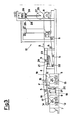
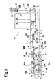
- a type of machine generally indicated by the reference numeral 10 in Figures 3-5 is used, which has such a structure as to comprise conveyor belt means, constituted by a felt belt 4, running along a closed-loop path, supported by rolls 5 and driven by a driving roll 6 installed at an end of said closed-loop path.
- the machine 10 comprises at least a first tank 7 and a second tank 8, inside which tanks there is a cement mixture in the fluid state, composed by cement and water, to which different fibrous materials are respectively added according to the tanks (for example, cellulose, and asbestos, also in fibre form).
- a cement mixture in the fluid state, composed by cement and water, to which different fibrous materials are respectively added according to the tanks (for example, cellulose, and asbestos, also in fibre form).
- first dipping roll 9 and a second dipping roll 11 of perforated structure for example made from net, revolving around their own axes, respectively 12 and 13.
- the dipping rolls 9 and 11 are antagonist rolls respectively relatively to a first coucher roll 14 and a second coucher roll 15, and between them the felt belt 4 runs.
- the coucher rolls 14 and 15 are supported by su pport means 16, which are capable of changing their mutual position relatively to the dipping rolls 9 and 11.
- Such means 16 have been made according to different modalities, according to whether the simultaneous engagement of both of the coucher rolls 14 and 15 with the dipping rolls 9 and 11 has to be also mechanically prevented, or less.
- the means 16 for changing the mutual position of the coucher rolls - dipping rolls within the relevant roll pairs comprise a rocker device comprising a pair of parallel, rocking arms 17 (only one of which is visible in figure 2), arranged around a hinge pivot 18 positioned in correspondence of their middle point and respectively supporting at their first ends and at their second ends the first coucher roll 14 and the second coucher roll 15.
- the felt belt 4 supporting means are not provided in the region of the first coucher roll 14, because in correspondence of such a roll the felt belt 4 reverses its direction of movement.
- the second coucher roll 15 is disengaged from the contact with the second dipping roll 11, the roll 19 performs the task of supporting the felt belt 4.
- the rocker device oscillates around the hinge pivot 18 thanks to hydraulic cylinders 20 parallel to uprights 21 which support the felt belt 4.
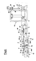
- a second form of practical embodiment of the means 16 for varying the mutual position of the coucher rolls - dipping rolls within the relevant roll pairs, shown in Figure 4, makes it possible the coucher rolls 14 and 15 to come into engagement with the respective dipping rolls 9 and 11 either alternatively or simultaneously, thanks to the fact that each one of said rocker arms 17 is subdivided into two half-arms 17A and 17B oscillating around the common hinge pivot 18 and are actuated by hydraulic cylinders 20A and 20B.
- the user evaluates, on the basis of his experience, whether such a possibility should be taken advantage of, or not.
- the two arms 17A and 17B are no longer hinged on one common hinge pivot, but are hinged by means of two distinct hinge rolls 18A and 18B supported by distinct uprights 21A and 21B, with the hydraulic cylinders 20A and 20B being installed parallel to these latter.
- the recovery of tension is constant and immediate thanks to means of compensation of the length of the belt 4, generally indicated by the reference numeral 21.
- Such means 21 comprise a first fixed roll 22 and a first mobile roll 23 sliding perpendicularly to its own axis. Along its path, the belt 4 by running returns around both of said rolls, running along an "S"-shaped path.
- the mobile roll 23 is kept pressed against the belt 4 thanks to the load applied to it, in the herein illustrated cases, by elastic means 24, namely an either compressed or stretched spring.
- the tension recovery means 21 can also be accomplished by means of hydraulic or pneumatic devices.
- the temporary support or core 25 is provided, which revolves around its axis 27 and cooperates with pressing rolls 26 also revolving around their axis 28 and translating perpendicularly to it during their motion of approaching to the core 25.
- the process for forming the tube by using the machine 10 is disclosed in the following particular, but not exclusive, reference to Figure 2, wherein the machine 10 is shown with the first dipping roll 12 and the first coucher roll 14 being engaged into contact with the felt belt 4, and with the second dippin g roll 11 and the second coucher roll 15 being disengaged.
- the felt belt 4 runs in the direction of the arrow "G".
- the first dipping roll 9 revolves around its own axis 12, draws an elementary layer of cement mixture, containing cellulose fibres, and deposits said elementary layer of cement mixture on the felt belt 4 throughout its whole width.
- the elementary layer of cement mortar decreases in fluidity thanks to the partial absorption of water through the porous structure of the felt belt, owing to the presence of sucking boxes during its motion of approaching towards the core 25.
- the elementary layer of cement mixture which has a thickness of about 0.2 mm, comes in the nearby of the core 25 in its best conditions in order to adhere to it, so the subsequent step of adhesion and wrapping takes place spontaneously by simple contact, and is anyway favoured by the action of the pressing rolls 26.
- the wrapping of the elementary layer of cement mixture takes place by successive spirals, until the desired thickness for the first layer of cement mixture of the tube is reached.
- the second rolls 15 and 11 are engaged with each other thus depositing, with the same modalities as of the first ones, an elementary layer of cement mixture coming from the second tank 8, and therefore containing the asbestos fibres, which goes to form a second layer of cement mixture of the tube, superimposed to the first layer, so as to obtain a tube consisting of one single cement mattrix free from discontinuities, even if it is reinforced with fibres of materials of different nature.
- the wrapped core 25 is replaced by another one in order to obtain a new tube.
- the extremely high versatility is evident of the machine 10, which makes it possible a tube to be obtained, which may also be constituted by more than two superimposed layers of different materials, by simply varying the number of the tanks, so as to have available a plurality of cement mixtures, or the number of steps of mixture drawing from said tanks, or both of them.
- tubes having a consequently changed diameter can be obtained.
- the advantages offered by the tube according to the present invention are the following: - functional characteristics typical of the tubes of asbestos cement, - high chemical characteristics of the inner/outer layers, thanks to the use of cement having a high resistance to aggressive chemicals, - high resistance to wear and ageing thanks to the monolithic structure of the manufactured tubes, which do not undergo any differential heat expansions.
- the present invention solves the technical problem in a particularly cheap way owing to the following reasons: - it makes it possible the use to be continued of materials which are already customarily used in the concerned field, such as, e.g., cellulose fibres, which, besides having a low cost, display a known behaviour over time; therefore, it is not necessary to perform experimental tests on the product which uses it, before throwing it on the market, with consequent savings in costs and risks.
- materials which are already customarily used in the concerned field such as, e.g., cellulose fibres, which, besides having a low cost, display a known behaviour over time; therefore, it is not necessary to perform experimental tests on the product which uses it, before throwing it on the market, with consequent savings in costs and risks.
Landscapes
- Engineering & Computer Science (AREA)
- Mechanical Engineering (AREA)
- Manufacturing & Machinery (AREA)
- Chemical & Material Sciences (AREA)
- Ceramic Engineering (AREA)
- General Engineering & Computer Science (AREA)
- Laminated Bodies (AREA)
- Rigid Pipes And Flexible Pipes (AREA)
Applications Claiming Priority (2)
| Application Number | Priority Date | Filing Date | Title |
|---|---|---|---|
| IT21042/88A IT1217869B (it) | 1988-06-20 | 1988-06-20 | Tubo a struttura cementizia metodo e macchina per la sua realizzazione |
| IT2104288 | 1988-06-20 |
Publications (2)
| Publication Number | Publication Date |
|---|---|
| EP0347962A2 true EP0347962A2 (de) | 1989-12-27 |
| EP0347962A3 EP0347962A3 (de) | 1991-06-26 |
Family
ID=11175839
Family Applications (1)
| Application Number | Title | Priority Date | Filing Date |
|---|---|---|---|
| EP19890201372 Withdrawn EP0347962A3 (de) | 1988-06-20 | 1989-05-30 | Rohr mit einer Struktur aus Zement, Verfahren und Gerät zu seiner Herstellung |
Country Status (2)
| Country | Link |
|---|---|
| EP (1) | EP0347962A3 (de) |
| IT (1) | IT1217869B (de) |
Cited By (1)
| Publication number | Priority date | Publication date | Assignee | Title |
|---|---|---|---|---|
| WO1998036886A1 (en) * | 1997-02-18 | 1998-08-27 | D & H Piping Systems (Proprietary) Limited | Corrosion resistant concrete pipe and process and apparatus for making the pipe |
Family Cites Families (3)
| Publication number | Priority date | Publication date | Assignee | Title |
|---|---|---|---|---|
| DE1030751B (de) * | 1951-03-30 | 1958-05-22 | Eternit Sa Franc | Verfahren zur Herstellung von zusammengesetzten Rohren, welche eine Aussenschicht aus Asbestzement und eine innere Betonauskleidung aufweisen |
| US3553077A (en) * | 1967-03-31 | 1971-01-05 | Johns Manville | Asbestos-portland cement pipes with monoethanolamines, diethanolamines,and triethanolamines as quick-setting agents |
| GB1592931A (en) * | 1978-05-25 | 1981-07-15 | Tac Construction Materials Ltd | Pipe manufacture |
-
1988
- 1988-06-20 IT IT21042/88A patent/IT1217869B/it active
-
1989
- 1989-05-30 EP EP19890201372 patent/EP0347962A3/de not_active Withdrawn
Cited By (1)
| Publication number | Priority date | Publication date | Assignee | Title |
|---|---|---|---|---|
| WO1998036886A1 (en) * | 1997-02-18 | 1998-08-27 | D & H Piping Systems (Proprietary) Limited | Corrosion resistant concrete pipe and process and apparatus for making the pipe |
Also Published As
| Publication number | Publication date |
|---|---|
| IT8821042A0 (it) | 1988-06-20 |
| EP0347962A3 (de) | 1991-06-26 |
| IT1217869B (it) | 1990-03-30 |
Similar Documents
| Publication | Publication Date | Title |
|---|---|---|
| US4119748A (en) | Steel cord reinforced plastic materials | |
| CN105715882B (zh) | 一种小口径的竹缠绕复合管及其制造方法 | |
| US2973293A (en) | Liquid fuel containers | |
| US2797469A (en) | Metalized glass fibers and products thereof | |
| DE159942T1 (de) | Fluorpolymerzusammenstellungen und verfahren zu deren herstellung. | |
| EP0347962A2 (de) | Rohr mit einer Struktur aus Zement, Verfahren und Gerät zu seiner Herstellung | |
| CZ296022B6 (cs) | Keramický výrobek odolný proti tepelným rázům | |
| US4312904A (en) | Fast-hardening hydraulic cement mass and surfacing method using the mass | |
| GB2106012A (en) | Reinforced sheet material | |
| CN2646519Y (zh) | 一种可扁平盘卷的液体输送软管 | |
| SU1598861A3 (ru) | Материал дл изготовлени уплотнительных и теплоизолирующих элементов | |
| CN216201244U (zh) | 瓦楞龙骨增强玻璃钢复合管及其连接结构及其生产设备 | |
| JPS63308275A (ja) | パツキン | |
| CN223191180U (zh) | 一种竹篾编织管为内衬结构层的纤维增强复合材料缠绕复合管 | |
| CN2173251Y (zh) | 填充四氟线 | |
| CN1028353C (zh) | 立式异形网壁脱液桶离心机 | |
| CN219912085U (zh) | 连续缠绕编织成型原位固化cipp内衬软管 | |
| CN1021077C (zh) | 聚四氟乙烯-橡胶复合补偿器及其制造方法 | |
| CN2399584Y (zh) | 柔性织物伸缩节 | |
| CN221991151U (zh) | 一种石棉胶管 | |
| CN2229992Y (zh) | 一种无缝传送带 | |
| CN217869181U (zh) | 一种拼接碳碳埚邦 | |
| CN113103540A (zh) | 一种带纤维增强钢丝缠绕胶管及制备方法、胶料制备方法 | |
| JPS5811111A (ja) | Grc補強陶管とその製造方法 | |
| CN1420009A (zh) | 玻璃钢筒气压脱模方法 |
Legal Events
| Date | Code | Title | Description |
|---|---|---|---|
| PUAI | Public reference made under article 153(3) epc to a published international application that has entered the european phase |
Free format text: ORIGINAL CODE: 0009012 |
|
| AK | Designated contracting states |
Kind code of ref document: A2 Designated state(s): AT BE CH DE ES FR GB GR LI LU NL SE |
|
| PUAL | Search report despatched |
Free format text: ORIGINAL CODE: 0009013 |
|
| AK | Designated contracting states |
Kind code of ref document: A3 Designated state(s): AT BE CH DE ES FR GB GR LI LU NL SE |
|
| STAA | Information on the status of an ep patent application or granted ep patent |
Free format text: STATUS: THE APPLICATION IS DEEMED TO BE WITHDRAWN |
|
| 18D | Application deemed to be withdrawn |
Effective date: 19911228 |