EP0347916A1 - Electromagnetic fuel metering and atomizing valve - Google Patents
Electromagnetic fuel metering and atomizing valve Download PDFInfo
- Publication number
- EP0347916A1 EP0347916A1 EP89111395A EP89111395A EP0347916A1 EP 0347916 A1 EP0347916 A1 EP 0347916A1 EP 89111395 A EP89111395 A EP 89111395A EP 89111395 A EP89111395 A EP 89111395A EP 0347916 A1 EP0347916 A1 EP 0347916A1
- Authority
- EP
- European Patent Office
- Prior art keywords
- valve
- nozzle
- holes
- fuel
- axial
- Prior art date
- Legal status (The legal status is an assumption and is not a legal conclusion. Google has not performed a legal analysis and makes no representation as to the accuracy of the status listed.)
- Withdrawn
Links
- 239000000446 fuel Substances 0.000 title claims abstract description 63
- 230000008093 supporting effect Effects 0.000 claims abstract description 20
- 238000004891 communication Methods 0.000 claims abstract description 5
- 230000006854 communication Effects 0.000 claims abstract description 5
- 125000006850 spacer group Chemical group 0.000 claims description 5
- 238000002485 combustion reaction Methods 0.000 claims description 3
- 238000011144 upstream manufacturing Methods 0.000 description 9
- 230000015572 biosynthetic process Effects 0.000 description 3
- 230000001771 impaired effect Effects 0.000 description 3
- 238000007789 sealing Methods 0.000 description 3
- 238000003754 machining Methods 0.000 description 2
- 230000002000 scavenging effect Effects 0.000 description 2
- 206010037660 Pyrexia Diseases 0.000 description 1
- 230000004323 axial length Effects 0.000 description 1
- 230000008878 coupling Effects 0.000 description 1
- 238000010168 coupling process Methods 0.000 description 1
- 238000005859 coupling reaction Methods 0.000 description 1
- 238000004519 manufacturing process Methods 0.000 description 1
- 239000000203 mixture Substances 0.000 description 1
- 230000000284 resting effect Effects 0.000 description 1
Images

Classifications
-
- F—MECHANICAL ENGINEERING; LIGHTING; HEATING; WEAPONS; BLASTING
- F02—COMBUSTION ENGINES; HOT-GAS OR COMBUSTION-PRODUCT ENGINE PLANTS
- F02M—SUPPLYING COMBUSTION ENGINES IN GENERAL WITH COMBUSTIBLE MIXTURES OR CONSTITUENTS THEREOF
- F02M53/00—Fuel-injection apparatus characterised by having heating, cooling or thermally-insulating means
- F02M53/04—Injectors with heating, cooling, or thermally-insulating means
-
- F—MECHANICAL ENGINEERING; LIGHTING; HEATING; WEAPONS; BLASTING
- F02—COMBUSTION ENGINES; HOT-GAS OR COMBUSTION-PRODUCT ENGINE PLANTS
- F02M—SUPPLYING COMBUSTION ENGINES IN GENERAL WITH COMBUSTIBLE MIXTURES OR CONSTITUENTS THEREOF
- F02M51/00—Fuel-injection apparatus characterised by being operated electrically
- F02M51/06—Injectors peculiar thereto with means directly operating the valve needle
- F02M51/061—Injectors peculiar thereto with means directly operating the valve needle using electromagnetic operating means
- F02M51/0625—Injectors peculiar thereto with means directly operating the valve needle using electromagnetic operating means characterised by arrangement of mobile armatures
- F02M51/0664—Injectors peculiar thereto with means directly operating the valve needle using electromagnetic operating means characterised by arrangement of mobile armatures having a cylindrically or partly cylindrically shaped armature, e.g. entering the winding; having a plate-shaped or undulated armature entering the winding
- F02M51/0667—Injectors peculiar thereto with means directly operating the valve needle using electromagnetic operating means characterised by arrangement of mobile armatures having a cylindrically or partly cylindrically shaped armature, e.g. entering the winding; having a plate-shaped or undulated armature entering the winding the armature acting as a valve or having a short valve body attached thereto
-
- F—MECHANICAL ENGINEERING; LIGHTING; HEATING; WEAPONS; BLASTING
- F02—COMBUSTION ENGINES; HOT-GAS OR COMBUSTION-PRODUCT ENGINE PLANTS
- F02M—SUPPLYING COMBUSTION ENGINES IN GENERAL WITH COMBUSTIBLE MIXTURES OR CONSTITUENTS THEREOF
- F02M51/00—Fuel-injection apparatus characterised by being operated electrically
- F02M51/06—Injectors peculiar thereto with means directly operating the valve needle
- F02M51/061—Injectors peculiar thereto with means directly operating the valve needle using electromagnetic operating means
- F02M51/0625—Injectors peculiar thereto with means directly operating the valve needle using electromagnetic operating means characterised by arrangement of mobile armatures
- F02M51/0664—Injectors peculiar thereto with means directly operating the valve needle using electromagnetic operating means characterised by arrangement of mobile armatures having a cylindrically or partly cylindrically shaped armature, e.g. entering the winding; having a plate-shaped or undulated armature entering the winding
- F02M51/0671—Injectors peculiar thereto with means directly operating the valve needle using electromagnetic operating means characterised by arrangement of mobile armatures having a cylindrically or partly cylindrically shaped armature, e.g. entering the winding; having a plate-shaped or undulated armature entering the winding the armature having an elongated valve body attached thereto
- F02M51/0675—Injectors peculiar thereto with means directly operating the valve needle using electromagnetic operating means characterised by arrangement of mobile armatures having a cylindrically or partly cylindrically shaped armature, e.g. entering the winding; having a plate-shaped or undulated armature entering the winding the armature having an elongated valve body attached thereto the valve body having cylindrical guiding or metering portions, e.g. with fuel passages
- F02M51/0678—Injectors peculiar thereto with means directly operating the valve needle using electromagnetic operating means characterised by arrangement of mobile armatures having a cylindrically or partly cylindrically shaped armature, e.g. entering the winding; having a plate-shaped or undulated armature entering the winding the armature having an elongated valve body attached thereto the valve body having cylindrical guiding or metering portions, e.g. with fuel passages all portions having fuel passages, e.g. flats, grooves, diameter reductions
-
- F—MECHANICAL ENGINEERING; LIGHTING; HEATING; WEAPONS; BLASTING
- F02—COMBUSTION ENGINES; HOT-GAS OR COMBUSTION-PRODUCT ENGINE PLANTS
- F02M—SUPPLYING COMBUSTION ENGINES IN GENERAL WITH COMBUSTIBLE MIXTURES OR CONSTITUENTS THEREOF
- F02M51/00—Fuel-injection apparatus characterised by being operated electrically
- F02M51/06—Injectors peculiar thereto with means directly operating the valve needle
- F02M51/08—Injectors peculiar thereto with means directly operating the valve needle specially for low-pressure fuel-injection
Definitions
- the present invention relates to an electromagnetic fuel metering and atomizing valve for an internal combustion engine fuel supply device.
- valves of the aforementioned type substantially comprise a cylindrical supporting body having a first axial cavity housing an electromagnet, and an axial hole communicating with said cavity and housing a core and an axially-sliding anchor integral with a mobile plugging member.
- Said valves also comprise a nozzle secured to and projecting axially from the supporting body, and in which is formed a fuel outlet hole communicating with said axial cavity and controlled by said plugging member. This is designed to move, by virtue of an electromagnet, between a first closed position wherein it is pushed by a spring against a seat on the nozzle, thus closing the fuel outlet hole, and an open position wherein the fuel outlet hole is opened.
- Said valves present a duct for feeding the fuel (piped to the valve) into a chamber communicating with said fuel outlet hole.
- Said fuel duct usually comprises an axial hole through the core and anchor on the valve, and further passages formed between further members and said supporting body and nozzle. On said valves, therefore, fuel is fed into said chamber along a duct originating at the top end and extending along the entire axial length of the valve.
- a major drawback of known valves of the aforementioned type is the formation of fuel vapours inside the fuel duct, which results in impaired operation of the valve in terms of metering and atomizing performance. This is particularly noticeable when operating with high-temperature fuel, as when the vehicle is left in the sun for prolonged periods of time.
- the pressure at which the fuel is fed into the chamber communicating with the fuel supply hole is not strictly constant, and rarely corresponds to the set pressure.
- the fuel supply circuit to the valve presents a pressure regulator for maintaining substantially constant fuel supply pressure.
- the pressure inside the chamber differs from that of said upstream portion due to the resistance encountered by the fuel in the duct portion formed inside the valve.
- valves failure of such valves to provide for strictly constant fuel pressure, correspondng to the set pressure, immediately upstream from the fuel outlet hole, invariably results, as already stated, in impaired metering and atomizing performance.
- the chamber formed inside the valve, immediately upstream from the fuel outlet hole is supplied with fuel through holes formed inside a portion of the nozzle close to the chamber itself.
- valves of the aforementioned type fail to provide a solution to the drawbacks caused by the formation of fuel vapours.
- valves of this sort featuring fuel outlet holes on the nozzle involve fairly complex machining operations, thus resulting in high manufacturing cost of the valve as a whole.
- the aim of the present invention is to provide an electromagnetic fuel metering and atomizing valve designed to overcome the drawbacks typically associated with known valves of the aforementioned type, i.e. a valve providing for efficient metering and atomizing performance under all operating conditions; which is of straightforward design, and may be produced cheaply by virtue of involving no complex mechanical machining.
- an electromagnetic fuel metering and atomizing valve for an internal combustion fuel supply device, said valve substantially comprising: . a substantially cylindrical supporting body having a first axial cavity housing an electromagnet and a core, and an axial hole communicating with said first cavity and housing an anchor integral with a mobile plugging member; .
- a nozzle secured to and projecting axially from said supporting body, and in which is formed an outlet hole communicating with said axial cavity and controlled by said plugging member; said plugging member being moved, by virtue of said electromagnet, between a first closed position, wherein it is pushed by a spring against a seat on said nozzle, thus closing said outlet hole, and an open position wherein said outlet hole is opened; characterised by the fact that said body presents a first and second series of holes designed to enable external communication, through the lateral surface of said supporting body, of said axial hole formed inside said body; the holes in one said series being separated from those of the other in the direction of the axis of said body.
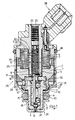
- the valve according to the present invention comprises a supporting body 1 defined by a substantially cylindrical lateral surface 2, and having a first axial cavity 3 housing an electromagnet 4, and an axial hole 5 communicating with said cavity 3.
- Axial hole 6 on electromagnet 4 houses a core 7, while axial hole 5 houses an axially-sliding anchor 8 integral with a mobile plugging member 9.
- Supporting body 1 is fitted with a nozzle 12 in which is formed a fuel outlet hole 13 controlled by plugging member 9.
- plugging member 9 is conveniently integral with a rod 14 sliding axially inside a cylindrical seat 15 on nozzle 12, and guided by a pair of annular projections 16 on which are formed flat portions 17, each defining a fuel passage together with the cylindrical surface of seat 15.
- a spacer 18 is fitted between nozzle 12 and body 1, and nozzle 12 is secured to body 1 by permanently deforming the annular end edge 19 of body 1.
- Anchor 8 is substantially tubular and secured to rod 14, e.g. by permanently deforming the end of anchor 8.
- a helical spring 20 having one end resting on a push rod 22 force-fitted inside an axial hole 23 on core 7, and designed to normally maintain plugging member 9 against a seat 24 upstream from fuel outlet hole 13.
- supporting body 1 presents two series of holes 25, 26 designed to enable external communication of axial hole 5 through lateral surface 2 of body 1.
- the holes in said first series are separated from those of said second series in the direction of the axis of body 1.
- the holes in said first series 25 consist of radial holes coming out inside cavity 3 of body 1; while those of said second series 26 consist of radial holes coming out inside a second axial cavity 27 on body 1, housing the top end of nozzle 12 and spacer 18.
- nozzle 12 presents an annular projection 28 defining, together with axial cavity 27, an annular fuel chamber 29 inside which the holes of said second series 26 come out.
- Spacer 18 also presents a slot for connecting chamber 29 to axial hole 5, to seat 15 inside nozzle 12 and, consequently, to fuel outlet hole 13.
- the end of rod 14 presents at least one hole 31 for connecting the hole in anchor 8 to seat 15 of nozzle 12.
- body 1 and part of nozzle 12 are conveniently covered by a plastic casing 35 having holes corresponding with those of said first and second series 25 and 26. Between cover 35 and body 1, there is provided a mesh filter 36.
- the valve also comprises known electrical connecting members 38 for supplying electromagnet 4, a cap 39 for nozzle 12, and a sealing ring 40.
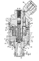
- the Fig.2 embodiment differs from that of Fig.1 solely as regards the design of nozzle 12 and plugging member 9, which, in this case, is in the form of a plate.
- plate 9 is integral with anchor 8, which is guided by a coupling 41 fitted inside the axial hole on core 7.
- a ring 42 is conveniently provided between anchor 8 and plate 9.
- Fuel outlet hole 13 is formed inside top wall 43 of nozzle 12 and comes out inside an axial hole 44 on the same.
- the Fig.2 embodiment also presents two series of holes 25, 26, the first series 25 coming out inside cavity 3 in body 1, and the second series 26 inside annular chamber 29 formed between nozzle 12 and cavity 27 in body 1.
- the valve according to the present invention operates as follows.
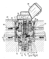
- the valve according to the present invention When connected to a fuel circuit of the type shown in Fig.3, the valve according to the present invention is housed inside a substantially cylindrical seat 45 having a hole 46 communicating with the manifold supplying the mixture to the engine.
- a substantially cylindrical seat 45 having a hole 46 communicating with the manifold supplying the mixture to the engine.
- pressure is exerted on the surface of hole 46 by sealing ring 40 which, together with a further sealing ring 48 between the valve and seat 45, seals the fuel inside seat 45.
- Fuel is fed into seat 45 along a duct 49 preferably located in line with said first series of holes 25, and is drained from seat 45 by a further duct 50.
- the fuel supplied by duct 49 is maintained at a predeter necessarilymined pressure by a pressure regulator (not shown) on the fuel circuit upstream from duct 49.
- the incoming fuel from duct 49 therefore fills seat 45 and enters the valve through both series of holes 25 and 26, as shown by the black arrows in Fig.3.
- a first stream of fuel through holes 26 flows into annular chamber 29 immediately upstream from outlet hole 13, and into seat 15 on nozzle 12 through slot 30 in spacer 18 and the cavities formed between the flat portions of annular projections 16 and the surface of seat 15.
- a second stream of fuel through holes 25 flows into cavity 3 housing electromagnet 4, and, via the openings between core 7, anchor 8 and the surfaces of hole 5 in body 1 and hole 6 in electromagnet 4, flows over the outer surfaces of all the members inside cavity 3 and axial hole 5, and out along duct 50.
- the presence of radial hole 32 in core 7 facilitates said passage.
- Part of the fuel in said first stream through holes 26 may also flow through hole 31 in rod 14 of plugging member 9 into the axial holes on anchor 8 and core 7.
- Said first stream of fuel through holes 26 therefore substantially supplies outlet hole 13 along said route inside the valve, the reduced length and, consequently, reduced resistance of which provide for minimal load losses, so that the fuel at outlet hole 13 presents substantially the same pressure as inside supply duct 49.
- said second stream of fuel through holes flows through all the openings and holes inside body 1, particularly those at the top of the valve, thus providing for effective scavenging of any vapours formed inside the same.
- valve according to the present invention has been found to overcome the drawbacks typically associated with known substantially axial fuel feed type valves, wherein the metering and atomizing efficiency of the valve is seriously impaired by the formation of vapours, particularly at the top of the valve. Moreover, metering and atomizing performance is improved by virtue of the high, substantially constant fuel pressure maintained immediately upstream from outlet hole 13.
- the valve according to the present invention may also be incorporated in a fuel circuit as shwon in Fig.4, which differs from the Fig.3 circuit by presenting a further two ducts 51 and 52, of which duct 51 provides for supplying the valve with fuel through holes 26, and duct 52 for drainage.
- the fuel supply pressure along duct 51 is preferably higher than that of duct 49, so that duct 51 substantially provides for supplying fuel to outlet hole 13, and duct 49 for scavenging as described previously.
Landscapes
- Engineering & Computer Science (AREA)
- Chemical & Material Sciences (AREA)
- Combustion & Propulsion (AREA)
- Mechanical Engineering (AREA)
- General Engineering & Computer Science (AREA)
- Physics & Mathematics (AREA)
- Electromagnetism (AREA)
- Fuel-Injection Apparatus (AREA)
Applications Claiming Priority (2)
| Application Number | Priority Date | Filing Date | Title |
|---|---|---|---|
| IT6759088 | 1988-06-23 | ||
| IT67590/88A IT1219397B (it) | 1988-06-23 | 1988-06-23 | Valvola per la dosatura e la polverizzazione di carburante ad azionamento elettromagnetico provvista di doppia serie di fori laterali di ingresso del carburante |
Publications (1)
| Publication Number | Publication Date |
|---|---|
| EP0347916A1 true EP0347916A1 (en) | 1989-12-27 |
Family
ID=11303680
Family Applications (1)
| Application Number | Title | Priority Date | Filing Date |
|---|---|---|---|
| EP89111395A Withdrawn EP0347916A1 (en) | 1988-06-23 | 1989-06-22 | Electromagnetic fuel metering and atomizing valve |
Country Status (3)
| Country | Link |
|---|---|
| US (1) | US4971291A (it) |
| EP (1) | EP0347916A1 (it) |
| IT (1) | IT1219397B (it) |
Cited By (3)
| Publication number | Priority date | Publication date | Assignee | Title |
|---|---|---|---|---|
| WO2005073547A1 (de) * | 2004-01-30 | 2005-08-11 | Robert Bosch Gmbh | Kabeldurchführung und brennstoffsystemteil mit einer kabeldurchführung |
| WO2006042798A1 (de) * | 2004-10-20 | 2006-04-27 | Robert Bosch Gmbh | Magnetventilbetätigter kraftstoffinjektor mit hydraulischem überhubanschlag |
| CN101302927B (zh) * | 2008-07-07 | 2011-12-14 | 薛永祥 | 一种计量控制阀及应用该计量控制阀的油井质量在线计量装置 |
Families Citing this family (7)
| Publication number | Priority date | Publication date | Assignee | Title |
|---|---|---|---|---|
| IT214617Z2 (it) * | 1988-06-23 | 1990-05-09 | Weber Srl | Ugello per una valvola di dosatura e di polverizzazione del carburanteper un dispositivo di alimentazione di un motore a combustione interna |
| IT1231875B (it) * | 1989-03-14 | 1992-01-14 | Weber Srl | Perfezionamento nel circuito di alimentazione del carburante in una valvola per l'iniezione del carburante per un motore a combustione interna ad azionamento elettromagnetico |
| JP2761405B2 (ja) * | 1989-06-27 | 1998-06-04 | 三信工業株式会社 | 内燃機関の燃料噴射装置 |
| US5100102A (en) * | 1990-10-15 | 1992-03-31 | Ford Motor Company | Compact electronic fuel injector |
| DE19739150A1 (de) * | 1997-09-06 | 1999-03-11 | Bosch Gmbh Robert | Brennstoffeinspritzventil |
| JP2001263521A (ja) * | 2000-03-17 | 2001-09-26 | Denso Corp | 電磁駆動装置およびそれを用いた流体制御弁と電磁駆動装置の製造方法 |
| GB201408060D0 (en) * | 2014-05-07 | 2014-06-18 | Delphi Int Operations Lux Srl | Connector assembly for a fuel injector |
Citations (10)
| Publication number | Priority date | Publication date | Assignee | Title |
|---|---|---|---|---|
| JPS606065A (ja) * | 1983-06-24 | 1985-01-12 | Automob Antipollut & Saf Res Center | 燃料噴射弁 |
| FR2553834A1 (fr) * | 1983-10-20 | 1985-04-26 | Sibe | Soupape d'injection pour moteur a combustion interne |
| JPS6079154A (ja) * | 1983-10-06 | 1985-05-04 | Nippon Denso Co Ltd | 電子制御式燃料噴射装置 |
| JPS60261972A (ja) * | 1984-06-07 | 1985-12-25 | Mitsubishi Motors Corp | 電磁式燃料噴射弁 |
| JPS62162769A (ja) * | 1986-01-13 | 1987-07-18 | Hitachi Ltd | 電磁式燃料噴射弁 |
| EP0232475A1 (de) * | 1986-01-31 | 1987-08-19 | VDO Adolf Schindling AG | Elektromagnetisch betätigbares Kraftstoffeinspritzventil |
| GB2187332A (en) * | 1986-02-19 | 1987-09-03 | Weber Srl | Electromagnetic fuel metering and atomizing valve |
| GB2196181A (en) * | 1984-03-05 | 1988-04-20 | Gerhard Mesenich | Electromagnetic injection valve |
| GB2198589A (en) * | 1986-11-15 | 1988-06-15 | Hitachi Ltd | Electromagnetic fuel injectors |
| FR2616485A1 (fr) * | 1987-06-09 | 1988-12-16 | Weber Srl | Valve d'atomisation et dosage de carburant pour un dispositif d'injection de carburant d'un moteur a combustion interne |
Family Cites Families (14)
| Publication number | Priority date | Publication date | Assignee | Title |
|---|---|---|---|---|
| DE2342109C2 (de) * | 1973-08-21 | 1983-10-27 | Robert Bosch Gmbh, 7000 Stuttgart | Elektromechanisch gesteuertes Kraftstoffeinspritzventil für Brennkraftmaschinen |
| DE2458728A1 (de) * | 1974-12-12 | 1976-06-24 | Bosch Gmbh Robert | Elektromagnetisch betaetigbares einspritzventil |
| DE2725135C2 (de) * | 1977-06-03 | 1987-01-15 | Robert Bosch Gmbh, 7000 Stuttgart | Elektromagnetisches Kraftstoff- Einspritzventil für Brennkraftmaschinen |
| DE3046889A1 (de) * | 1980-12-12 | 1982-07-15 | Robert Bosch Gmbh, 7000 Stuttgart | Elektromagnetisch betaetigbares ventil, insbesondere kraftstoffeinspritzventil fuer kraftstoffeinspritzanlagen |
| DE3120160A1 (de) * | 1981-05-21 | 1982-12-09 | Robert Bosch Gmbh, 7000 Stuttgart | Elektromagnetisch betaetigbares ventil, insbesondere kraftstoffeinspritzventil fuer kraftstoffeinspritzan lagen |
| DE3143848A1 (de) * | 1981-11-05 | 1983-05-11 | Robert Bosch Gmbh, 7000 Stuttgart | Elektromagnetisch betaetigbares ventil, insbesondere kraftstoffeinspritzventil |
| DE3207918A1 (de) * | 1982-03-05 | 1983-09-15 | Robert Bosch Gmbh, 7000 Stuttgart | Elektromagnetisch betaetigbares ventil |
| JPS6032973A (ja) * | 1983-08-01 | 1985-02-20 | Automob Antipollut & Saf Res Center | 燃料噴射弁 |
| JPS60240865A (ja) * | 1984-05-16 | 1985-11-29 | Automob Antipollut & Saf Res Center | 電磁式燃料噴射弁 |
| JPS6179860A (ja) * | 1984-09-26 | 1986-04-23 | Hitachi Ltd | 電磁式燃料噴射弁 |
| JPS6179859A (ja) * | 1984-09-27 | 1986-04-23 | Nippon Denso Co Ltd | 電磁式燃料噴射弁 |
| IT1183889B (it) * | 1985-06-11 | 1987-10-22 | Weber Spa | Valvola per la dosatura del carburante per un dispositivo di alimentazione di un motore a combustione interna |
| DE3705587C2 (de) * | 1987-02-21 | 1994-01-27 | Bosch Gmbh Robert | Elektromagnetisch betätigtes Ventil, insbesondere Kraftstoffeinspritzventil |
| US4798329A (en) * | 1987-03-03 | 1989-01-17 | Colt Industries Inc. | Combined fuel injector and pressure regulator assembly |
-
1988
- 1988-06-23 IT IT67590/88A patent/IT1219397B/it active
-
1989
- 1989-06-22 EP EP89111395A patent/EP0347916A1/en not_active Withdrawn
-
1990
- 1990-04-10 US US07/513,052 patent/US4971291A/en not_active Expired - Fee Related
Patent Citations (10)
| Publication number | Priority date | Publication date | Assignee | Title |
|---|---|---|---|---|
| JPS606065A (ja) * | 1983-06-24 | 1985-01-12 | Automob Antipollut & Saf Res Center | 燃料噴射弁 |
| JPS6079154A (ja) * | 1983-10-06 | 1985-05-04 | Nippon Denso Co Ltd | 電子制御式燃料噴射装置 |
| FR2553834A1 (fr) * | 1983-10-20 | 1985-04-26 | Sibe | Soupape d'injection pour moteur a combustion interne |
| GB2196181A (en) * | 1984-03-05 | 1988-04-20 | Gerhard Mesenich | Electromagnetic injection valve |
| JPS60261972A (ja) * | 1984-06-07 | 1985-12-25 | Mitsubishi Motors Corp | 電磁式燃料噴射弁 |
| JPS62162769A (ja) * | 1986-01-13 | 1987-07-18 | Hitachi Ltd | 電磁式燃料噴射弁 |
| EP0232475A1 (de) * | 1986-01-31 | 1987-08-19 | VDO Adolf Schindling AG | Elektromagnetisch betätigbares Kraftstoffeinspritzventil |
| GB2187332A (en) * | 1986-02-19 | 1987-09-03 | Weber Srl | Electromagnetic fuel metering and atomizing valve |
| GB2198589A (en) * | 1986-11-15 | 1988-06-15 | Hitachi Ltd | Electromagnetic fuel injectors |
| FR2616485A1 (fr) * | 1987-06-09 | 1988-12-16 | Weber Srl | Valve d'atomisation et dosage de carburant pour un dispositif d'injection de carburant d'un moteur a combustion interne |
Non-Patent Citations (4)
| Title |
|---|
| PATENT ABSTRACTS OF JAPAN, Vol. 10, No. 138 (M-480)(2195) 21 May 1986; & JP,A,60 261 972 (MITSUBISHI JIDOSHA KOGYO) 25 December 1985, the whole document. * |
| PATENT ABSTRACTS OF JAPAN, Vol. 11, No. 397 (M-655)(2844) 25 December 1987; & JP,A,62 162 769 (HITACHI) 25 December 1985, the whole document. * |
| PATENT ABSTRACTS OF JAPAN, Vol. 9, No. 121 (M-382)(1844) 25 May 1985; & JP,A,60 006 065 (JIDOSHA KOGAI ANZEN KIKI GIJUTSU KENKYU KUMIAI) 12 January 1985, the whole document. * |
| PATENT ABSTRACTS OF JAPAN, Vol. 9, No. 220 (E-341)(1943) 06 September 1985; & JP,A,60 079 154 (NIPPON DENSO) 04 May 1985, the whole document. * |
Cited By (4)
| Publication number | Priority date | Publication date | Assignee | Title |
|---|---|---|---|---|
| WO2005073547A1 (de) * | 2004-01-30 | 2005-08-11 | Robert Bosch Gmbh | Kabeldurchführung und brennstoffsystemteil mit einer kabeldurchführung |
| CN100532822C (zh) * | 2004-01-30 | 2009-08-26 | 罗伯特·博世有限公司 | 电缆穿引装置及具有该电缆穿引装置的燃料系统部件 |
| WO2006042798A1 (de) * | 2004-10-20 | 2006-04-27 | Robert Bosch Gmbh | Magnetventilbetätigter kraftstoffinjektor mit hydraulischem überhubanschlag |
| CN101302927B (zh) * | 2008-07-07 | 2011-12-14 | 薛永祥 | 一种计量控制阀及应用该计量控制阀的油井质量在线计量装置 |
Also Published As
| Publication number | Publication date |
|---|---|
| US4971291A (en) | 1990-11-20 |
| IT1219397B (it) | 1990-05-11 |
| IT8867590A0 (it) | 1988-06-23 |
Similar Documents
| Publication | Publication Date | Title |
|---|---|---|
| US4395988A (en) | Fuel injection system | |
| US5060868A (en) | Electromagnetically actuatable valve | |
| EP0776418B1 (en) | Improved flow area armature for fuel injector | |
| US20030155445A1 (en) | Fuel injection valve with a filter bush | |
| US5934252A (en) | Fuel injection system | |
| US5348233A (en) | High volume gaseous fuel injector | |
| US4678124A (en) | Electromagnetically actuatable valve in particular a fuel injection valve | |
| JPH05500257A (ja) | 電磁作動式の燃料噴射弁 | |
| US4648368A (en) | Fuel injection system | |
| WO1989004919A2 (en) | Pico fuel injector valve | |
| GB2170270A (en) | Electromagnetic fuel injection valve | |
| JPS60256552A (ja) | 噴射弁 | |
| EP0347916A1 (en) | Electromagnetic fuel metering and atomizing valve | |
| EP0781914B1 (en) | Fuel interconnect for fuel injector | |
| US3247833A (en) | Fuel injection valves | |
| US5427319A (en) | Fuel injector armature assembly | |
| US6253789B1 (en) | Valve for metered introduction of volatilized fuel | |
| JPS5884281A (ja) | 電磁操作弁 | |
| US5641126A (en) | Fuel injection systems with compact filter mountings | |
| US4317542A (en) | Fuel injector | |
| US20040026541A1 (en) | Fuel injection valve | |
| EP0347914B1 (en) | Electromagnetic fuel metering and atomizing valve | |
| EP0649983B1 (en) | An electromagnetically operated fuel metering and atomising valve | |
| EP4698770A2 (en) | Fuel injector for gaseous fuel and valve seat for the same | |
| EP0781915A1 (en) | Fuel injector |
Legal Events
| Date | Code | Title | Description |
|---|---|---|---|
| PUAI | Public reference made under article 153(3) epc to a published international application that has entered the european phase |
Free format text: ORIGINAL CODE: 0009012 |
|
| AK | Designated contracting states |
Kind code of ref document: A1 Designated state(s): DE ES FR GB SE |
|
| 17P | Request for examination filed |
Effective date: 19900529 |
|
| 17Q | First examination report despatched |
Effective date: 19910516 |
|
| STAA | Information on the status of an ep patent application or granted ep patent |
Free format text: STATUS: THE APPLICATION IS DEEMED TO BE WITHDRAWN |
|
| 18D | Application deemed to be withdrawn |
Effective date: 19920416 |