EP0347654B1 - Détecteur de l'état de fonctionnement des freins - Google Patents
Détecteur de l'état de fonctionnement des freins Download PDFInfo
- Publication number
- EP0347654B1 EP0347654B1 EP89110341A EP89110341A EP0347654B1 EP 0347654 B1 EP0347654 B1 EP 0347654B1 EP 89110341 A EP89110341 A EP 89110341A EP 89110341 A EP89110341 A EP 89110341A EP 0347654 B1 EP0347654 B1 EP 0347654B1
- Authority
- EP
- European Patent Office
- Prior art keywords
- contact carrier
- housing
- wear
- brake
- temperature sensor
- Prior art date
- Legal status (The legal status is an assumption and is not a legal conclusion. Google has not performed a legal analysis and makes no representation as to the accuracy of the status listed.)
- Expired - Lifetime
Links
- 239000004020 conductor Substances 0.000 claims description 17
- 230000003628 erosive effect Effects 0.000 claims 1
- 239000002184 metal Substances 0.000 claims 1
- 238000013461 design Methods 0.000 description 3
- 238000004519 manufacturing process Methods 0.000 description 3
- 239000000463 material Substances 0.000 description 3
- 238000012546 transfer Methods 0.000 description 3
- UNILWMWFPHPYOR-KXEYIPSPSA-M 1-[6-[2-[3-[3-[3-[2-[2-[3-[[2-[2-[[(2r)-1-[[2-[[(2r)-1-[3-[2-[2-[3-[[2-(2-amino-2-oxoethoxy)acetyl]amino]propoxy]ethoxy]ethoxy]propylamino]-3-hydroxy-1-oxopropan-2-yl]amino]-2-oxoethyl]amino]-3-[(2r)-2,3-di(hexadecanoyloxy)propyl]sulfanyl-1-oxopropan-2-yl Chemical compound O=C1C(SCCC(=O)NCCCOCCOCCOCCCNC(=O)COCC(=O)N[C@@H](CSC[C@@H](COC(=O)CCCCCCCCCCCCCCC)OC(=O)CCCCCCCCCCCCCCC)C(=O)NCC(=O)N[C@H](CO)C(=O)NCCCOCCOCCOCCCNC(=O)COCC(N)=O)CC(=O)N1CCNC(=O)CCCCCN\1C2=CC=C(S([O-])(=O)=O)C=C2CC/1=C/C=C/C=C/C1=[N+](CC)C2=CC=C(S([O-])(=O)=O)C=C2C1 UNILWMWFPHPYOR-KXEYIPSPSA-M 0.000 description 2
- 238000005266 casting Methods 0.000 description 2
- 230000000694 effects Effects 0.000 description 2
- 238000005259 measurement Methods 0.000 description 2
- 238000004382 potting Methods 0.000 description 2
- 238000003466 welding Methods 0.000 description 2
- 230000015572 biosynthetic process Effects 0.000 description 1
- 239000000919 ceramic Substances 0.000 description 1
- 150000001875 compounds Chemical class 0.000 description 1
- 230000007797 corrosion Effects 0.000 description 1
- 238000005260 corrosion Methods 0.000 description 1
- 230000007547 defect Effects 0.000 description 1
- 230000001419 dependent effect Effects 0.000 description 1
- 230000008030 elimination Effects 0.000 description 1
- 238000003379 elimination reaction Methods 0.000 description 1
- 238000003780 insertion Methods 0.000 description 1
- 230000037431 insertion Effects 0.000 description 1
- 238000012423 maintenance Methods 0.000 description 1
- 238000003825 pressing Methods 0.000 description 1
- 230000003449 preventive effect Effects 0.000 description 1
- 230000011664 signaling Effects 0.000 description 1
- 230000007704 transition Effects 0.000 description 1
Images
Classifications
-
- F—MECHANICAL ENGINEERING; LIGHTING; HEATING; WEAPONS; BLASTING
- F16—ENGINEERING ELEMENTS AND UNITS; GENERAL MEASURES FOR PRODUCING AND MAINTAINING EFFECTIVE FUNCTIONING OF MACHINES OR INSTALLATIONS; THERMAL INSULATION IN GENERAL
- F16D—COUPLINGS FOR TRANSMITTING ROTATION; CLUTCHES; BRAKES
- F16D66/00—Arrangements for monitoring working conditions, e.g. wear, temperature
- F16D66/02—Apparatus for indicating wear
- F16D66/021—Apparatus for indicating wear using electrical detection or indication means
- F16D66/026—Apparatus for indicating wear using electrical detection or indication means indicating different degrees of lining wear
- F16D66/027—Sensors therefor
-
- F—MECHANICAL ENGINEERING; LIGHTING; HEATING; WEAPONS; BLASTING
- F16—ENGINEERING ELEMENTS AND UNITS; GENERAL MEASURES FOR PRODUCING AND MAINTAINING EFFECTIVE FUNCTIONING OF MACHINES OR INSTALLATIONS; THERMAL INSULATION IN GENERAL
- F16D—COUPLINGS FOR TRANSMITTING ROTATION; CLUTCHES; BRAKES
- F16D66/00—Arrangements for monitoring working conditions, e.g. wear, temperature
- F16D2066/001—Temperature
Definitions
- the invention relates to a sensor for the operating state of brakes with a wear sensor and a temperature sensor, which are embedded together in a sleeve-shaped housing, which can be inserted into a through hole in the brake shoe and brake pad such that an end face of the housing is essentially flush with the Brake pad friction surface.
- Such an encoder which is intended to trigger preventive maintenance by timely signaling in order to avoid impermissible operating states, and which is known to be used in an extremely harsh environment, must meet high requirements with regard to an undoubted function.
- Critical measurement conditions exist in particular with regard to the temperature sensor, which, apart from its suitability for high temperatures, must be arranged outside the wear area of the brake pad, but should measure the temperature of the friction or braking surface regardless of the degree of wear of the brake pad.
- such an encoder is also a wearing part that has to be reattached each time the brake pads are changed and should therefore also be inexpensive to produce and install without problems, in order to promote acceptance of the encoder.
- a combination of a wear sensor with a temperature switch which has become known from DE-A-21 44 466, can only be produced with relatively great effort, in particular because of the adjustment work required, and is unsuitable for series production due to the structural design.
- this solution is functionally questionable because a bimetal switch is used, the heat transfer is dependent on the degree of wear of the brake pad and in Heat transfer path bad heat conductors, namely an air cushion or the brake pad and several material transitions acting as defects, are located, and thus considerable heat loss and runtime effects are accepted.
- the object of the invention was therefore to find an architecture for a generic encoder which, despite extensive cost minimization and manufacture under large series conditions, ensures satisfactory reproducibility and a high degree of functional reliability.
- a metallic contact carrier which can be inserted flush with the friction surface is provided, which serves as a heat conductor and forms part of the wear sensor and in which the dimension in the wear or wear direction is greater than the maximum thickness of the brake pad, that a conductor of at least one signal circuit is welded to the contact carrier at a distance which determines the wear signal from its end which is flush with the friction surface, and that the temperature sensor is spatially directly assigned to the contact carrier outside the wear region defined by the weld.
- a preferred embodiment is characterized in that a loose connection is provided between the contact carrier and the housing, that the contact carrier is contacted with a ground line outside the wear area and that a connecting wire of the temperature sensor is welded to the contact carrier.
- the invention offers the advantage that, on the one hand, the thermal connection for the temperature sensor located outside the wear area and, on the other hand, the electrical connection, which is to be interrupted for the wear signal, is formed with a single component, the contact carrier.
- the preferred exemplary embodiment shown in the drawings has a structural unit which can be inserted loosely into the housing of the encoder, in which the ground contact serving press fits are avoided.
- Such ground contact is complex in terms of production technology and is unsafe due to susceptibility to corrosion and due to the movable and lubricated vehicle parts located in the further line connection.
- a simple stamped part is used as the contact carrier and a rigid attachment of the temperature sensor to the contact carrier is provided by means of a connecting wire.
- the direct spatial assignment of the temperature sensor to the contact carrier which is in physical contact with the friction or braking surface, also offers reproducible heat transfer conditions and a minimum of heat loss, in other words constant and low-hysteresis measurement conditions.
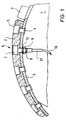
- FIGURE 1 shows a partially cut brake shoe 1, for example a drum brake with internal brake shoes.
- 2 denotes one of at least two brake pads fastened on a shoulder 3 of the brake shoe 1.
- the brake pads are usually fastened by means of a plurality of rivets, one of which is designated 4 and to which a cylindrical countersink 5 is assigned in each case in the brake pad 2.
- the encoder 6 according to the invention has an at least two-stage sleeve-shaped housing 7, which is designed in such a way that a housing section of larger diameter corresponds to the dimensions of the cylindrical countersink and a housing section of smaller diameter, which is provided with a thread 8, is equal to the diameter of the rivet shaft.
- the encoder 6 can be used in the provided for riveting the brake pad 2, not specified through holes in the brake pad 2 and the shoulder 3 of the brake shoe 1 and tighten by means of a nut 9 and an interposed disc 10 between the brake pad 2 and brake shoe 1.
- the encoder 6 is then assembled by pressing it into the rivet opening provided for the encoder 6. It has been shown that in this embodiment, screwing the encoder 6 is not absolutely necessary and thus the thread 8 can be omitted.
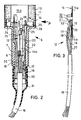
- the preferred embodiment of the encoder 6 shown in FIGURE 3 shows that an assembly 12 is inserted into the sleeve-shaped housing 7 and fastened by means of a temperature-resistant, ceramic casting compound 13 and sealed against the ingress of moisture. It goes without saying that the potting compound has approximately the same wear properties as the brake pad material, ie neither lubricates nor damages the brake drum.
- the assembly 12 consists of a contact carrier 14, which is produced as a simple stamped part, a temperature sensor 15, for example a resistance measuring element suitable for high temperatures, and a cable 16, from whose spliced conductors 17, 18, 19 and 20 conductors 17, 18 and 20 with the contact carrier 14, the conductor 19 with the one connecting wire 21 of the temperature sensor 15 are preferably contacted by spot welding.
- the latter connection point is covered by an insulating tube 22.
- the conductor 18 is part of a first signal circuit
- the conductor 17 is part of a second signal circuit
- the conductor 20 carries ground potential.
- the actual wear sensor is thus formed by the contact bridges formed by the spot welding between the contact carrier which is grounded via the conductor 20 and the conductors 17 and 18 of the signal circuits.
- the second connecting wire 23 of the temperature sensor is attached to the contact carrier 14, which also serves as a heat conductor, and is thus connected to ground. But at the same time it forms a rigid, mechanical connection between the temperature sensor 15 and the contact carrier 14, preferably in such a way that the temperature sensor 15 touches the contact carrier 14.
- a broad section 14a and a narrower section 14b are formed on the contact carrier 14 corresponding to the stepped opening or through-bore of the sleeve-shaped transmitter housing 7, which is not designated.
- the shoulders 24 and 25 resulting from this design limit the insertion path during assembly of the assembly 12 by striking the step face 26 of the housing opening.
- the end face of the section 14a of the contact carrier 14 is essentially in the plane of the end face of the encoder housing and thus always in a position flush with the friction surface.
- Recesses 27 and 28 of different depths are provided for total elimination when the respective signal circuits are interrupted by the brake-related removal of the contact carrier in the area of the respective cut conductor 17 or 18.
- the distance s shown represents the amount of removal that is still permissible between a first signal and a second signal which is more distinctive in the signal effect.
- the tabs 29 and 30 formed on the contact carrier serve to center the assembly 12 when it is inserted into the housing 7, it not being absolutely necessary that they be in contact with the housing opening after the potting compound 13 has been introduced.
- a strain relief in the form of a hose nozzle 31 is assigned to the cable 16 led out of the transmitter 6, i. H. the hose nozzle 31 is shrunk on the one hand on the cable 16 and on the other hand on a hose connector 32 formed axially on the housing 7.
Landscapes
- Engineering & Computer Science (AREA)
- General Engineering & Computer Science (AREA)
- Mechanical Engineering (AREA)
- Braking Arrangements (AREA)
Claims (6)
- Capteur (6) pour l'état de fonctionnement de freins avec un capteur d'usure (14, 17, 18, 20) et avec un capteur de température (15) qui sont logés conjointement dans un boîtier (7) en forme de douille qui peut être inséré dans un alésage de passage pratiqué dans un segment de frein (1) et une garniture de frein (2) d'un frein, de telle sorte qu'une face frontale du boîtier (7) soit, pour l'essentiel, à fleur de la surface de friction de ladite garniture de frein (2),
caractérisé par le fait
qu'il est prévu, pour pouvoir être introduit dans ledit boîtier (7), à fleur de la surface de friction, un support porte-contact métallique (14) qui sert de conducteur thermique et représente une partie du capteur d'usure (14, 17, 18, 20) et pour lequel la dimension dans le sens de l'usure ou de l'enlèvement est plus grande que l'épaisseur maximale de la garniture de frein (2),
qu'un conducteur (17) d'au moins un circuit de courant de signal est soudé sur le support porte-contact (14) à une distance de l'extrémité à fleur de la surface de friction déterminant l'émission du signal d'usure et
que le capteur de température (15) est spatialement directement associé au support porte-contact (14) en dehors de la zone d'usure définie par le point de soudure. - Capteur selon la revendication 1,
caractérisé par le fait
qu'il est prévu un assemblage lâche entre le support porte-contact (14) et le boîtier (7),
que ledit support porte-contact (14) est relié, en dehors de la zone d'usure, à une ligne de masse (20). - Capteur selon la revendication 1,
caractérisé par le fait
qu'un fil de raccordement (23) du capteur de température (15) est soudé sur le support porte-contact (14). - Capteur selon la revendication 1,
caractérisé par le fait
que le support porte-contact (14) a été réalisé sous la forme d'une pièce estampée plate pouvant âtre introduite parallèlement à l'axe dans le boîtier (7). - Capteur selon la revendication 1,
caractérisé par le fait
que des pattes de centrage (29, 30) sont moulées sur le support porte-contact (14). - Capteur selon la revendication 1,
caractérisé par le fait
que, conformément à une ouverture graduée du boîtier (7), le support porte-contact (14) présente une section large (14a) et une section étroite (14b),
que, en partant des épaulements (24, 25) situés entre lesdites deux sections (14a, 14b), des évidements (27, 28) de profondeurs différentes sont prévus dans la section large (14a) et
qu au fond respectif desdits évidements (27, 28) est soudé respectivement un conducteur (17, 18) d'un circuit de courant de signal.
Applications Claiming Priority (2)
| Application Number | Priority Date | Filing Date | Title |
|---|---|---|---|
| DE8807884U DE8807884U1 (de) | 1988-06-18 | 1988-06-18 | Geber für den Betriebszustand von Bremsen |
| DE8807884U | 1988-06-18 |
Publications (3)
| Publication Number | Publication Date |
|---|---|
| EP0347654A2 EP0347654A2 (fr) | 1989-12-27 |
| EP0347654A3 EP0347654A3 (en) | 1990-10-31 |
| EP0347654B1 true EP0347654B1 (fr) | 1993-08-04 |
Family
ID=6825147
Family Applications (1)
| Application Number | Title | Priority Date | Filing Date |
|---|---|---|---|
| EP89110341A Expired - Lifetime EP0347654B1 (fr) | 1988-06-18 | 1989-06-08 | Détecteur de l'état de fonctionnement des freins |
Country Status (2)
| Country | Link |
|---|---|
| EP (1) | EP0347654B1 (fr) |
| DE (2) | DE8807884U1 (fr) |
Families Citing this family (7)
| Publication number | Priority date | Publication date | Assignee | Title |
|---|---|---|---|---|
| DE4139546A1 (de) * | 1991-11-30 | 1993-06-03 | Bosch Gmbh Robert | System zum erkennen des verschleisses eines bremsbelags |
| DE102004051054A1 (de) † | 2004-10-19 | 2006-04-20 | Repower Systems Ag | Vorrichtung für eine Windenergieanlage |
| DE102006059785A1 (de) | 2006-12-15 | 2008-06-26 | Pex Kabeltechnik Gmbh | Bremsanlage für ein Fahrzeug |
| US8739938B2 (en) * | 2012-02-01 | 2014-06-03 | GM Global Technology Operations LLC | Friction brake with a resistive sensor |
| CN107606003A (zh) * | 2017-10-17 | 2018-01-19 | 青岛约克运输设备有限公司 | 一种制动器温度检测传感器结构 |
| CN110578763A (zh) * | 2018-06-08 | 2019-12-17 | 派德森(京山)汽车零部件有限公司 | 鼓式制动蹄片的磨损指示装置 |
| CN116476794A (zh) * | 2023-03-13 | 2023-07-25 | 东风柳州汽车有限公司 | 车辆制动器检测方法及检测装置 |
Family Cites Families (4)
| Publication number | Priority date | Publication date | Assignee | Title |
|---|---|---|---|---|
| US3674114A (en) * | 1970-09-11 | 1972-07-04 | Bendix Corp | Brake lining temperature probe |
| US3958445A (en) * | 1973-08-30 | 1976-05-25 | The Bendix Corporation | Proportional brake lining wear sensor |
| JPS59127934U (ja) * | 1983-02-15 | 1984-08-28 | 松下電器産業株式会社 | 摩耗度兼温度検知装置 |
| DE3502053C2 (de) * | 1985-01-23 | 1994-12-08 | Wabco Vermoegensverwaltung | Einrichtung zur Anzeige des Verschleißes eines Bauteils |
-
1988
- 1988-06-18 DE DE8807884U patent/DE8807884U1/de not_active Expired
-
1989
- 1989-06-08 EP EP89110341A patent/EP0347654B1/fr not_active Expired - Lifetime
- 1989-06-08 DE DE8989110341T patent/DE58905116D1/de not_active Expired - Fee Related
Also Published As
| Publication number | Publication date |
|---|---|
| DE58905116D1 (de) | 1993-09-09 |
| EP0347654A2 (fr) | 1989-12-27 |
| DE8807884U1 (de) | 1988-08-11 |
| EP0347654A3 (en) | 1990-10-31 |
Similar Documents
| Publication | Publication Date | Title |
|---|---|---|
| EP2687823B1 (fr) | Dispositif destiné à l'enregistrement et au traitement de valeurs de mesure de capteur et/ou à la commande d'actionneurs | |
| EP1068120B1 (fr) | Bloc de composants detecteurs de pression | |
| DE102009041951B4 (de) | Messanordnung zur Zuspannkraftmessung einer Scheibenbremse und eine entsprechende Scheibenbremse | |
| DE19632820C2 (de) | Verteilerplatte für elektrische Anschlüsse | |
| DE3005542C2 (fr) | ||
| EP0347654B1 (fr) | Détecteur de l'état de fonctionnement des freins | |
| EP0829003B1 (fr) | Detecteur de pression et procede permettant de le produire | |
| DE69809379T2 (de) | Druckwandler | |
| EP0616144A1 (fr) | Capteur pour indicateur d'usure à niveaux multiples, en particulier pour garnitures de freins | |
| EP0297429B1 (fr) | Capteur pour la condition de travail des freins | |
| DE102006019895A1 (de) | Strommessvorrichtung mit speziell kontaktierter Leiterplatte und entsprechendes Herstellungsverfahren | |
| DE3035887A1 (de) | Bremsbelag, insbesondere fuer scheibenbremsen, mit einem eingebauten abnutzungsanzeigekontakt | |
| EP1313109A2 (fr) | Résistance à montage en surface | |
| DE10259629B4 (de) | Brems-oder Kupplungsbelag mit integrierter Kraftmessung | |
| DE3915996C1 (en) | Vehicle brake limiting wear sensor - has thick-film resistor on ceramic substrate fixed in opening of brake lining | |
| EP0754875B1 (fr) | Dispositif de garniture pour frein à disque ainsi que procédé pour son obtention | |
| DE19751574C2 (de) | Verfahren zum Verstemmen eines Betätigungselements mit einer Betätigungswelle | |
| DE60201606T2 (de) | Bremsbelagverschleisssensor | |
| EP0742380B1 (fr) | Indicateur d'usure à étages multiples pour garnitures de frein | |
| DE3815994C2 (fr) | ||
| EP0191305A2 (fr) | Dispositif pour mesurer la charge d'essieu de véhicules | |
| EP1714534A1 (fr) | Composant electronique pour element support | |
| DE69400165T2 (de) | Einrichtung zum Erfassen des Verschleisses von Reibbelägen | |
| EP1158199B1 (fr) | Dispositif d'indication d'usure pour garnitures de freins à disque | |
| EP1162694B1 (fr) | Appareil pour la connexion de conducteurs électriques |
Legal Events
| Date | Code | Title | Description |
|---|---|---|---|
| PUAI | Public reference made under article 153(3) epc to a published international application that has entered the european phase |
Free format text: ORIGINAL CODE: 0009012 |
|
| AK | Designated contracting states |
Kind code of ref document: A2 Designated state(s): CH DE ES FR GB IT LI NL SE |
|
| PUAL | Search report despatched |
Free format text: ORIGINAL CODE: 0009013 |
|
| AK | Designated contracting states |
Kind code of ref document: A3 Designated state(s): CH DE ES FR GB IT LI NL SE |
|
| 17P | Request for examination filed |
Effective date: 19901220 |
|
| 17Q | First examination report despatched |
Effective date: 19911104 |
|
| RAP1 | Party data changed (applicant data changed or rights of an application transferred) |
Owner name: MANNESMANN KIENZLE GMBH (HR B1220) |
|
| GRAA | (expected) grant |
Free format text: ORIGINAL CODE: 0009210 |
|
| AK | Designated contracting states |
Kind code of ref document: B1 Designated state(s): CH DE ES FR GB IT LI NL SE |
|
| PG25 | Lapsed in a contracting state [announced via postgrant information from national office to epo] |
Ref country code: SE Effective date: 19930804 Ref country code: ES Free format text: THE PATENT HAS BEEN ANNULLED BY A DECISION OF A NATIONAL AUTHORITY Effective date: 19930804 |
|
| REF | Corresponds to: |
Ref document number: 58905116 Country of ref document: DE Date of ref document: 19930909 |
|
| ITF | It: translation for a ep patent filed | ||
| GBT | Gb: translation of ep patent filed (gb section 77(6)(a)/1977) |
Effective date: 19931027 |
|
| ET | Fr: translation filed | ||
| PGFP | Annual fee paid to national office [announced via postgrant information from national office to epo] |
Ref country code: CH Payment date: 19940516 Year of fee payment: 6 |
|
| PLBE | No opposition filed within time limit |
Free format text: ORIGINAL CODE: 0009261 |
|
| STAA | Information on the status of an ep patent application or granted ep patent |
Free format text: STATUS: NO OPPOSITION FILED WITHIN TIME LIMIT |
|
| 26N | No opposition filed | ||
| PG25 | Lapsed in a contracting state [announced via postgrant information from national office to epo] |
Ref country code: NL Effective date: 19950101 |
|
| NLV4 | Nl: lapsed or anulled due to non-payment of the annual fee | ||
| PG25 | Lapsed in a contracting state [announced via postgrant information from national office to epo] |
Ref country code: LI Effective date: 19950630 Ref country code: CH Effective date: 19950630 |
|
| REG | Reference to a national code |
Ref country code: CH Ref legal event code: PL |
|
| REG | Reference to a national code |
Ref country code: GB Ref legal event code: IF02 |
|
| PGFP | Annual fee paid to national office [announced via postgrant information from national office to epo] |
Ref country code: GB Payment date: 20020610 Year of fee payment: 14 |
|
| PGFP | Annual fee paid to national office [announced via postgrant information from national office to epo] |
Ref country code: FR Payment date: 20020625 Year of fee payment: 14 |
|
| PGFP | Annual fee paid to national office [announced via postgrant information from national office to epo] |
Ref country code: DE Payment date: 20020819 Year of fee payment: 14 |
|
| PG25 | Lapsed in a contracting state [announced via postgrant information from national office to epo] |
Ref country code: GB Free format text: LAPSE BECAUSE OF NON-PAYMENT OF DUE FEES Effective date: 20030608 |
|
| PG25 | Lapsed in a contracting state [announced via postgrant information from national office to epo] |
Ref country code: DE Free format text: LAPSE BECAUSE OF NON-PAYMENT OF DUE FEES Effective date: 20040101 |
|
| GBPC | Gb: european patent ceased through non-payment of renewal fee |
Effective date: 20030608 |
|
| PG25 | Lapsed in a contracting state [announced via postgrant information from national office to epo] |
Ref country code: FR Free format text: LAPSE BECAUSE OF NON-PAYMENT OF DUE FEES Effective date: 20040227 |
|
| REG | Reference to a national code |
Ref country code: FR Ref legal event code: ST |
|
| PG25 | Lapsed in a contracting state [announced via postgrant information from national office to epo] |
Ref country code: IT Free format text: LAPSE BECAUSE OF NON-PAYMENT OF DUE FEES;WARNING: LAPSES OF ITALIAN PATENTS WITH EFFECTIVE DATE BEFORE 2007 MAY HAVE OCCURRED AT ANY TIME BEFORE 2007. THE CORRECT EFFECTIVE DATE MAY BE DIFFERENT FROM THE ONE RECORDED. Effective date: 20050608 |