EP0347654B1 - Brake operation status detector - Google Patents
Brake operation status detector Download PDFInfo
- Publication number
- EP0347654B1 EP0347654B1 EP89110341A EP89110341A EP0347654B1 EP 0347654 B1 EP0347654 B1 EP 0347654B1 EP 89110341 A EP89110341 A EP 89110341A EP 89110341 A EP89110341 A EP 89110341A EP 0347654 B1 EP0347654 B1 EP 0347654B1
- Authority
- EP
- European Patent Office
- Prior art keywords
- contact carrier
- housing
- wear
- brake
- temperature sensor
- Prior art date
- Legal status (The legal status is an assumption and is not a legal conclusion. Google has not performed a legal analysis and makes no representation as to the accuracy of the status listed.)
- Expired - Lifetime
Links
Images
Classifications
-
- F—MECHANICAL ENGINEERING; LIGHTING; HEATING; WEAPONS; BLASTING
- F16—ENGINEERING ELEMENTS AND UNITS; GENERAL MEASURES FOR PRODUCING AND MAINTAINING EFFECTIVE FUNCTIONING OF MACHINES OR INSTALLATIONS; THERMAL INSULATION IN GENERAL
- F16D—COUPLINGS FOR TRANSMITTING ROTATION; CLUTCHES; BRAKES
- F16D66/00—Arrangements for monitoring working conditions, e.g. wear, temperature
- F16D66/02—Apparatus for indicating wear
- F16D66/021—Apparatus for indicating wear using electrical detection or indication means
- F16D66/026—Apparatus for indicating wear using electrical detection or indication means indicating different degrees of lining wear
- F16D66/027—Sensors therefor
-
- F—MECHANICAL ENGINEERING; LIGHTING; HEATING; WEAPONS; BLASTING
- F16—ENGINEERING ELEMENTS AND UNITS; GENERAL MEASURES FOR PRODUCING AND MAINTAINING EFFECTIVE FUNCTIONING OF MACHINES OR INSTALLATIONS; THERMAL INSULATION IN GENERAL
- F16D—COUPLINGS FOR TRANSMITTING ROTATION; CLUTCHES; BRAKES
- F16D66/00—Arrangements for monitoring working conditions, e.g. wear, temperature
- F16D2066/001—Temperature
Landscapes
- Engineering & Computer Science (AREA)
- General Engineering & Computer Science (AREA)
- Mechanical Engineering (AREA)
- Braking Arrangements (AREA)
Description
Die Erfindung betrifft einen Geber für den Betriebszustand von Bremsen mit einem Verschleißsensor und einem Temperatursensor, welche gemeinsam in einem hülsenförmigen Gehäuse eingebettet sind, das in eine in Bremsbacke und Bremsbelag befindliche Durchgangsbohrung derart einsetzbar ist, daß eine Stirnfläche des Gehäuses im wesentlichen bündig ist mit der Reibfläche des Bremsbelages.The invention relates to a sensor for the operating state of brakes with a wear sensor and a temperature sensor, which are embedded together in a sleeve-shaped housing, which can be inserted into a through hole in the brake shoe and brake pad such that an end face of the housing is essentially flush with the Brake pad friction surface.
An einen derartigen Geber, der, um unzulässige Betriebszustände zu vermeiden, durch rechtzeitige Signalgabe eine vorbeugende Wartung auslösen soll und der bekanntermaßen in einem außerordentlich rauhen Milieu eingesetzt ist, müssen hohe Anforderungen hinsichtlich einer zweifelsfreien Funktion gestellt werden. Kritische Meßbedingungen bestehen insbesondere hinsichtlich des Temperatursensors, der,von der Eignung für hohe Temperaturen abgesehen, außerhalb des Verschleißbereichs des Bremsbelages angeordnet werden muß, die Temperatur der Reib- bzw. Bremsfläche aber unabhängig vom Abnutzungsgrad des Bremsbelags erfassen sollte. Ein solcher Geber ist andererseits aber auch ein Verschleißteil, das bei jedem Bremsbelagwechsel neu anzubringen ist und somit, auch um die Akzeptanz des Gebers zu fördern, kostengünstig herstellbar und problemlos montierbar sein sollte.Such an encoder, which is intended to trigger preventive maintenance by timely signaling in order to avoid impermissible operating states, and which is known to be used in an extremely harsh environment, must meet high requirements with regard to an undoubted function. Critical measurement conditions exist in particular with regard to the temperature sensor, which, apart from its suitability for high temperatures, must be arranged outside the wear area of the brake pad, but should measure the temperature of the friction or braking surface regardless of the degree of wear of the brake pad. On the other hand, such an encoder is also a wearing part that has to be reattached each time the brake pads are changed and should therefore also be inexpensive to produce and install without problems, in order to promote acceptance of the encoder.
Eine durch die DE-A-21 44 466 bekannt gewordene Kombination eines Verschleißsensors mit einem Temperaturschalter ist insbesondere wegen der erforderlichen Justierarbeit nur mit relativ hohem Aufwand herstellbar und aufgrund des konstruktiven Aufbaus für die Serienfertigung ungeeignet. Andererseits ist diese Lösung funktionell fragwürdig deshalb, weil ein Bimetallschalter Anwendung findet, die Wärmeübertragung abhängig ist vom Abnutzungsgrad des Bremsbelages und im Wärmeübertragungsweg schlechte Wärmeleiter, nämlich ein Luftpolster bzw. der Bremsbelag und mehrere als Störstellen wirkende Materialübergänge, sich befinden, und somit erheblicher Wärmeverlust und Laufzeiteffekte in Kauf zu nehmen sind.A combination of a wear sensor with a temperature switch, which has become known from DE-A-21 44 466, can only be produced with relatively great effort, in particular because of the adjustment work required, and is unsuitable for series production due to the structural design. On the other hand, this solution is functionally questionable because a bimetal switch is used, the heat transfer is dependent on the degree of wear of the brake pad and in Heat transfer path bad heat conductors, namely an air cushion or the brake pad and several material transitions acting as defects, are located, and thus considerable heat loss and runtime effects are accepted.
Die Aufgabe der Erfindung bestand demnach darin, für einen gattungsgemäßen Geber eine Architektur zu finden, die trotz einer weitgehenden Kostenminimierung und einer Herstellung unter Großserienbedingungen eine zufriedenstellende Reproduzierbarkeit und einen hohen Grad an Funktionssicherheit gewährleistet.The object of the invention was therefore to find an architecture for a generic encoder which, despite extensive cost minimization and manufacture under large series conditions, ensures satisfactory reproducibility and a high degree of functional reliability.
Die Lösung dieser Aufgabe sieht vor, daß ein in das Gehäuse reibflächenbündig einsetzbarer, metallischer Kontaktträger vorgesehen ist, welcher als Wärmeleiter dient und einen Teil des Verschleißsensors darstellt und bei welchem das Abmaß in Verschleiß- bzw. Abtragungsrichtung größer ist als die maximale Stärke des Bremsbelages, daß an dem Kontaktträger in einem die Verschleißsignalgabe bestimmenden Abstand von dessen reibflächenbündigem Ende ein Leiter wenigstens eines Signalstromkreises angeschweißt ist und daß der Temperatursensor außerhalb des durch die Schweißstelle definierten Verschleißbereichs dem Kontaktträger räumlich unmittelbar zugeordnet ist.The solution to this problem provides that a metallic contact carrier which can be inserted flush with the friction surface is provided, which serves as a heat conductor and forms part of the wear sensor and in which the dimension in the wear or wear direction is greater than the maximum thickness of the brake pad, that a conductor of at least one signal circuit is welded to the contact carrier at a distance which determines the wear signal from its end which is flush with the friction surface, and that the temperature sensor is spatially directly assigned to the contact carrier outside the wear region defined by the weld.
Ein bevorzugtes Ausführungsbeispiel ist dadurch gekennzeichnet, daß zwischen dem Kontaktträger und dem Gehäuse eine lose Verbindung vorgesehen ist, daß der Kontaktträger außerhalb des Verschleißbereichs mit einer Masseleitung kontaktiert ist und daß ein Anschlußdraht des Temperatursensors mit dem Kontaktträger verschweißt ist.A preferred embodiment is characterized in that a loose connection is provided between the contact carrier and the housing, that the contact carrier is contacted with a ground line outside the wear area and that a connecting wire of the temperature sensor is welded to the contact carrier.
Die Erfindung bietet den Vorteil, daß einerseits die thermische Verbindung für den außerhalb des Verschleißbereichs befindlichen Temperatursensor, andererseits die elektrische Verbindung, welche für die Verschleißsignalgabe zu unterbrechen ist, mit einem einzigen Bauteil, dem Kontaktträger, gebildet wird. Das bevorzugte, in den Zeichnungen dargestellte Ausführungsbeispiel weist eine in das Gehäuse des Gebers lose einführbare Baueinheit auf, bei der der Massekontaktierung dienende Preßpassungen vermieden sind. Eine derartige Massekontaktierung ist fertigungstechnisch aufwendig und durch Korrosionsanfälligkeit sowie aufgrund der in der weiteren Leitungsverbindung befindlichen, beweglichen und geschmierten Fahrzeugteile unsicher. Vorteilhaft ist ferner, daß als Kontaktträger ein einfaches Stanzteil verwendet wird und mittels eines Anschlußdrahtes eine starre Befestigung des Temperatursensors an den Kontaktträger vorgesehen ist. Dadurch wird, und zwar außerhalb des Gehäuses, eine genaue Positionierung von Verschleißsensor und Temperatursensor und letzten Endes die Bildung einer einfachen Baueinheit aus Kontaktträger, Temperatursensor und Kabelstrang, der vorzugsweise mit einer Steckverbindung abgeschlossen ist, ermöglicht. Die Werkzeug-und Materialkosten der gefundenen Lösung sind außerordentlich gering, bei der Montage des Gebers ist lediglich ein loses Zusammenfügen der funktionsfähig komplettierten Baueinheit und des Gehäuses und danach ein Vergießen erforderlich. Aufwendiges Einpressen und Justierarbeit sind vermieden, d. h. die gefundene Geberarchitektur ist maschinell montierbar.The invention offers the advantage that, on the one hand, the thermal connection for the temperature sensor located outside the wear area and, on the other hand, the electrical connection, which is to be interrupted for the wear signal, is formed with a single component, the contact carrier. The preferred exemplary embodiment shown in the drawings has a structural unit which can be inserted loosely into the housing of the encoder, in which the ground contact serving press fits are avoided. Such ground contact is complex in terms of production technology and is unsafe due to susceptibility to corrosion and due to the movable and lubricated vehicle parts located in the further line connection. It is also advantageous that a simple stamped part is used as the contact carrier and a rigid attachment of the temperature sensor to the contact carrier is provided by means of a connecting wire. As a result, an exact positioning of the wear sensor and the temperature sensor and, in the end, the formation of a simple structural unit from the contact carrier, the temperature sensor and the cable harness, which is preferably completed with a plug-in connection, is made possible. The tool and material costs of the solution found are extraordinarily low; all that is required for the assembly of the encoder is a loose assembly of the functionally completed structural unit and the housing and then casting. Time-consuming press-in and adjustment work are avoided, ie the encoder architecture found can be assembled by machine.
Die unmittelbare räumliche Zuordnung des Temperatursensors zum Kontaktträger, der in materiellem Kontakt zur Reib- bzw. Bremsfläche steht, bietet ferner gut reproduzierbare Wärmeübertragungsverhältnisse und ein Minimum an Wärmeverlust, mit anderen Worten konstante und hysteresearme Meßbedingungen.The direct spatial assignment of the temperature sensor to the contact carrier, which is in physical contact with the friction or braking surface, also offers reproducible heat transfer conditions and a minimum of heat loss, in other words constant and low-hysteresis measurement conditions.
Im folgenden sei die Erfindung anhand der Zeichnungen näher erläutert. Es zeigen
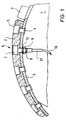
FIGUR 1 eine Übersichtsdarstellung, die die Anordnung des erfindungsgemäßen Gebers an beispielsweise einer Bremsbacke einer Trommelbremse zeigt,- FIGUR 2 einen Längsschnitt des bevorzugten Ausführungsbeispiels des erfindungsgemäßen Gebers und
FIGUR 3 eine Seitenansicht der in das Gehäuse des Gebers einsetzbaren Baueinheit gemäß Pfeilrichtung P in FIGUR 2.
- 1 shows an overview showing the arrangement of the sensor according to the invention on, for example, a brake shoe of a drum brake,
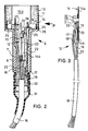
- FIGURE 2 is a longitudinal section of the preferred embodiment of the encoder according to the invention and
- FIG. 3 shows a side view of the structural unit that can be inserted into the housing of the transmitter, in the direction of arrow P in FIG. 2.
Die Übersichtsdarstellung FIGUR 1 zeigt eine teilweise geschnittene Bremsbacke 1 beispielsweise einer Trommelbremse mit innenliegenden Bremsbacken. Mit 2 ist einer von wenigstens zwei auf einer Schulter 3 der Bremsbacke 1 befestigten Bremsbelägen bezeichnet. Die Befestigung der Bremsbeläge erfolgt üblicherweise mittels mehrerer Niete, von denen eine mit 4 bezeichnet ist und denen im Bremsbelag 2 jeweils eine zylindrische Senkung 5 zugeordnet ist. Der neuerungsgemäße Geber 6 weist ein wenigstens zweistufiges hülsenförmiges Gehäuse 7 auf, welches derart gestaltet ist, daß ein Gehäuseabschnitt größeren Durchmessers den Maßen der zylindrischen Senkung entspricht und ein Gehäuseabschnitt kleineren Durchmessers, der mit einem Gewinde 8 versehen ist, gleich ist dem Durchmesser des Nietschaftes. Somit läßt sich der Geber 6 in für das Nieten des Bremsbelages 2 vorgesehene, nicht näher bezeichnete Durchgangsbohrungen im Bremsbelag 2 und der Schulter 3 der Bremsbacke 1 einsetzen und mittels einer Mutter 9 und einer zwischengelegten Scheibe 10 zwischen Bremsbelag 2 und Bremsbacke 1 festspannen. Als Variante ist es denkbar, beispielsweise den Gehäuseabschnitt größeren Durchmessers des Gebers 6 mit einem Rändel 11 (FIGUR 2) zu versehen, der gegenüber der Senkung 5 im Bremsbelag 2 ein Übermaß aufweist. Die Montage des Gebers 6 erfolgt dann durch Einpressen in die für den Geber 6 vorgesehene Nietöffnung. Dabei hat es sich gezeigt, daß bei dieser Ausführungsvariante ein Verschrauben des Gebers 6 nicht unbedingt erforderlich ist und somit auch das Gewinde 8 entfallen kann.The overview FIGURE 1 shows a partially cut
Das mit der FIGUR 3 dargestellte, bevorzugte Ausführungsbeispiel des Gebers 6 zeigt, daß in das hülsenförmige Gehäuse 7 eine Baugruppe 12 eingesetzt und mittels einer temperaturfesten, keramischen Vergußmasse 13 befestigt und gegen Eindringen von Feuchtigkeit abgedichtet ist. Dabei ist es selbstverständlich, daß die Vergußmasse annähernd die gleichen Verschleißeigenschaften wie das Bremsbelagmaterial aufweist, d. h. weder schmiert, noch die Bremstrommel beschädigt.The preferred embodiment of the
Die Baugruppe 12 besteht aus einem Kontaktträger 14, der als einfaches Stanzteil hergestellt ist, einem Temperatursensor 15, beispielsweise ein für hohe Tempraturen geeignetes Widerstandsmeßelement, und einem Kabel 16, von dessen aufgespleisten Leitern 17, 18, 19 und 20 die Leiter 17, 18 und 20 mit dem Kontaktträger 14, der Leiter 19 mit dem einen Anschlußdraht 21 des Temperatursensors 15 vorzugsweise durch Punktschweißen kontaktiert sind. Die letztgenannte Verbindungsstelle ist mittels eines Isolierschlauches 22 abgedeckt. Von den bezeichneten Leitern ist der Leiter 18 Teil eines ersten Signalstromkreises, der Leiter 17 Teil eines zweiten Signalstromkreises und der Leiter 20 führt Massepotential. Der eigentliche Verschleißsensor wird somit von den durch das Punktschweißen gebildeten Kontaktbrükken zwichen dem über den Leiter 20 an Masse liegenden Kontaktträger und den Leitern 17 und 18 der Signalstromkreise gebildet. Wie ferner aus der FIGUR 2 hervorgeht, ist der zweite Anschlußdraht 23 des Temperatursensors an dem zusätzlich als Wärmeleiter dienenden Kontaktträger 14 befestigt und somit mit Masse verbunden. Er bildet aber gleichzeitig eine starre, mechanische Verbindung zwischen dem Temperatursensor 15 und dem Kontaktträger 14, vorzugsweise derart, daß der Temperatursensor 15 den Kontaktträger 14 berührt.The
Der Vollständigkeit halber sei noch erwähnt, daß an dem Kontaktträger 14 entsprechend der nicht bezeichneten, gestuften Öffnung bzw. Durchgangsbohrung des hülsenförmigen Gebergehäuses 7 ein breiter Abschnitt 14a und ein schmalerer Abschnitt 14b ausgebildet sind. Die bei dieser Ausbildung sich ergebenden Schultern 24 und 25 begrenzen bei der Montage der Baugruppe 12 deren Einsteckweg, indem sie an der Stufenstirn 26 der Gehäuseöffnung anschlagen. Entsprechend der Gestaltung des Kontaktträgers 14, der dann achsparallel im Gebergehäuse 7 liegt, befindet sich nach der Montage die Stirnfläche des Abschnittes 14a des Kontaktträgers 14 im wesentlichen in der Ebene der Stirnfläche des Gebergehäuses und somit stets in einer reibflächenbündigen Lage.For the sake of completeness, it should also be mentioned that a broad section 14a and a
Unterschiedlich tiefe Ausparungen 27 und 28 sind dafür vorgesehen, daß beim Unterbrechen der jeweiligen Signalstromkreise durch die bremsbedingte Abtragung eine totale Beseitigung des Kontaktträgers im Bereich des jeweiligen angeschnittenen Leiters 17 bzw. 18 gegeben ist. Der eingezeichnete Abstand s stellt das Abtragungsmaß dar, das zwischen einem ersten Signal und einem in der Signalwirkung markanteren zweiten Signal noch zulässig ist. Die an dem Kontaktträger ausgebildeten Lappen 29 und 30 dienen der Zentrierung der Baugruppe 12 beim Einführen in das Gehäuse 7, wobei es nicht zwingend erforderlich ist, daß sie nach dem Einbringen der Vergußmasse 13 mit der Gehäuseöffnung in Berührung stehen.Recesses 27 and 28 of different depths are provided for total elimination when the respective signal circuits are interrupted by the brake-related removal of the contact carrier in the area of the
Dem aus dem Geber 6 herausgeführten Kabel 16 ist eine Zugentlastung in Form einer Schlauchtülle 31 zugeordnet, d. h. die Schlauchtülle 31 ist einerseits auf dem Kabel 16, andererseits auf einem am Gehäuse 7 axial angeformten Schlauchstutzen 32 aufgeschrumpft.A strain relief in the form of a
Claims (6)
- Pickup (6) for the operating state of brakes, having a wear sensor (14, 17, 18, 20) and a temperature sensor (15) which are embedded together in a sleeve-shaped housing (7) which can be inserted into a throughbore located in a brake shoe (1) and brake lining (2) of a brake such that one end face of the housing (7) is substantially flush with the friction surface of the brake lining (2), characterized in that there is provided a metal contact carrier (14) which can be inserted flush with the friction surface into the housing (7) and which serves as a heat conductor and represents part of the wear sensor (14, 17, 18, 20) and in which the dimension in the direction of wear or erosion is larger than the maximum thickness of the brake lining (2), in that a conductor (17) of at least one signal circuit is welded to the contact carrier (14) at a spacing from the end thereof which is flush with the friction surface which determines the giving of a wear signal, and in that the temperature sensor (15) is spatially directly associated with the contact carrier (14) outside the wear region defined by the weld point.
- Pickup according to Claim 1, characterized in that a loose connection is provided between the contact carrier (14) and the housing (7), and in that the contact carrier (14) is in contact with a line to earth (20) outside the wear region.
- Pickup according to Claim 1, characterized in that a connection wire (23) of the temperature sensor (15) is welded to the contact carrier (14).
- Pickup according to Claim 1, characterized in that the contact carrier (14) is constructed as a flat punched part which can be inserted axially parallel into the housing (7).
- Pickup according to Claim 1, characterized in that centring tabs (29, 30) are integrally formed on the contact carrier (14).
- Pickup according to Claim 1, characterized in that the contact carrier (14) has a wide section (14a) and a narrow section (14b) corresponding to a stepped opening in the housing (7), in that cutouts (27, 28) of different depths, starting from the shoulders (24, 25) located between the two sections (14a, 14b), are provided in the wide section (14a), and in that a respective conductor (17, 18) of a signal circuit is welded to the respective base of the cutouts (27, 28).
Applications Claiming Priority (2)
| Application Number | Priority Date | Filing Date | Title |
|---|---|---|---|
| DE8807884U | 1988-06-18 | ||
| DE8807884U DE8807884U1 (en) | 1988-06-18 | 1988-06-18 |
Publications (3)
| Publication Number | Publication Date |
|---|---|
| EP0347654A2 EP0347654A2 (en) | 1989-12-27 |
| EP0347654A3 EP0347654A3 (en) | 1990-10-31 |
| EP0347654B1 true EP0347654B1 (en) | 1993-08-04 |
Family
ID=6825147
Family Applications (1)
| Application Number | Title | Priority Date | Filing Date |
|---|---|---|---|
| EP89110341A Expired - Lifetime EP0347654B1 (en) | 1988-06-18 | 1989-06-08 | Brake operation status detector |
Country Status (2)
| Country | Link |
|---|---|
| EP (1) | EP0347654B1 (en) |
| DE (2) | DE8807884U1 (en) |
Families Citing this family (5)
| Publication number | Priority date | Publication date | Assignee | Title |
|---|---|---|---|---|
| DE4139546A1 (en) * | 1991-11-30 | 1993-06-03 | Bosch Gmbh Robert | SYSTEM FOR DETECTING THE WEAR OF A BRAKE PAD |
| DE102004051054A1 (en) † | 2004-10-19 | 2006-04-20 | Repower Systems Ag | Device for wind power plant for orientation of at least one movably installed component has at least one brake unit to maintain set orientation of component, and at least one sensor to monitor brake unit and detect error function |
| DE102006059785A1 (en) | 2006-12-15 | 2008-06-26 | Pex Kabeltechnik Gmbh | Brake system for a vehicle |
| US8739938B2 (en) * | 2012-02-01 | 2014-06-03 | GM Global Technology Operations LLC | Friction brake with a resistive sensor |
| CN107606003A (en) * | 2017-10-17 | 2018-01-19 | 青岛约克运输设备有限公司 | A kind of brake temperature detection sensor structure |
Family Cites Families (4)
| Publication number | Priority date | Publication date | Assignee | Title |
|---|---|---|---|---|
| US3674114A (en) * | 1970-09-11 | 1972-07-04 | Bendix Corp | Brake lining temperature probe |
| US3958445A (en) * | 1973-08-30 | 1976-05-25 | The Bendix Corporation | Proportional brake lining wear sensor |
| JPS59127934U (en) * | 1983-02-15 | 1984-08-28 | 松下電器産業株式会社 | Wear degree and temperature detection device |
| DE3502053C2 (en) * | 1985-01-23 | 1994-12-08 | Wabco Vermoegensverwaltung | Device for displaying the wear of a component |
-
1988
- 1988-06-18 DE DE8807884U patent/DE8807884U1/de not_active Expired
-
1989
- 1989-06-08 DE DE8989110341T patent/DE58905116D1/en not_active Expired - Fee Related
- 1989-06-08 EP EP89110341A patent/EP0347654B1/en not_active Expired - Lifetime
Also Published As
| Publication number | Publication date |
|---|---|
| EP0347654A3 (en) | 1990-10-31 |
| EP0347654A2 (en) | 1989-12-27 |
| DE8807884U1 (en) | 1988-08-11 |
| DE58905116D1 (en) | 1993-09-09 |
Similar Documents
| Publication | Publication Date | Title |
|---|---|---|
| EP1068120B1 (en) | Pressure sensor assembly | |
| EP2687823B1 (en) | Device for the recording and processing of sensor measurement values and/or for controlling actuators | |
| DE102009041951B4 (en) | Measuring arrangement for the application force of a disc brake and a corresponding disc brake | |
| DE19632820C2 (en) | Distribution board for electrical connections | |
| DE102006019895A1 (en) | Power measuring device for use as battery sensor for measuring e.g. battery power, of vehicle, has connecting unit for connecting contact unit with connector of board, where press fit is provided between connecting unit and hole | |
| DE4308272C1 (en) | Multi-stage wear indicator sensor for vehicle brake lining - has resistance network provided by thick-film circuit applied to metal ceramics substrate for brakes in vehicle or crane | |
| EP0829003B1 (en) | Pressure sensor and method of producing the same | |
| DE3005542C2 (en) | ||
| EP0347654B1 (en) | Brake operation status detector | |
| DE3035887C2 (en) | Brake lining, in particular for disc brakes, with a built-in wear indicator contact | |
| EP0297429B1 (en) | Sensor for the working condition of brakes | |
| EP1313109A2 (en) | Surface mount resistor | |
| DE102007008729B4 (en) | Sensing element for detecting a wear path of a brake pad | |
| DE10259629B4 (en) | Brake or clutch lining with integrated force measurement | |
| DE19751574C2 (en) | Method for caulking an actuating element with an actuating shaft | |
| DE19526607A1 (en) | Brake shoe assembly for disc brakes and process for their manufacture | |
| DE60201606T2 (en) | BREMSBELAGVERSCHLEISSSENSOR | |
| EP0742380B1 (en) | Multistep wear indicator for brake pads | |
| DE3815994C2 (en) | ||
| EP0191305A2 (en) | Device for measuring the axial load of vehicles | |
| EP1714534A1 (en) | Electronic component on a supporting element | |
| EP1162694B1 (en) | Apparatus for connecting electrical wires | |
| DE19504543C2 (en) | Process for forming connection bumps on electrically conductive microelectronic connection elements for solder bump-free tab bonding | |
| EP0903514B1 (en) | Railway vehicle brake system with condition monitoring. | |
| DE2657016A1 (en) | SPRING CONTACT MODULE FOR MEASURING AND TESTING PURPOSES |
Legal Events
| Date | Code | Title | Description |
|---|---|---|---|
| PUAI | Public reference made under article 153(3) epc to a published international application that has entered the european phase |
Free format text: ORIGINAL CODE: 0009012 |
|
| AK | Designated contracting states |
Kind code of ref document: A2 Designated state(s): CH DE ES FR GB IT LI NL SE |
|
| PUAL | Search report despatched |
Free format text: ORIGINAL CODE: 0009013 |
|
| AK | Designated contracting states |
Kind code of ref document: A3 Designated state(s): CH DE ES FR GB IT LI NL SE |
|
| 17P | Request for examination filed |
Effective date: 19901220 |
|
| 17Q | First examination report despatched |
Effective date: 19911104 |
|
| RAP1 | Party data changed (applicant data changed or rights of an application transferred) |
Owner name: MANNESMANN KIENZLE GMBH (HR B1220) |
|
| GRAA | (expected) grant |
Free format text: ORIGINAL CODE: 0009210 |
|
| AK | Designated contracting states |
Kind code of ref document: B1 Designated state(s): CH DE ES FR GB IT LI NL SE |
|
| PG25 | Lapsed in a contracting state [announced via postgrant information from national office to epo] |
Ref country code: SE Effective date: 19930804 Ref country code: ES Free format text: THE PATENT HAS BEEN ANNULLED BY A DECISION OF A NATIONAL AUTHORITY Effective date: 19930804 |
|
| REF | Corresponds to: |
Ref document number: 58905116 Country of ref document: DE Date of ref document: 19930909 |
|
| ITF | It: translation for a ep patent filed |
Owner name: DITTA SIAK S.P.A. |
|
| GBT | Gb: translation of ep patent filed (gb section 77(6)(a)/1977) |
Effective date: 19931027 |
|
| ET | Fr: translation filed | ||
| PGFP | Annual fee paid to national office [announced via postgrant information from national office to epo] |
Ref country code: CH Payment date: 19940516 Year of fee payment: 6 |
|
| PLBE | No opposition filed within time limit |
Free format text: ORIGINAL CODE: 0009261 |
|
| STAA | Information on the status of an ep patent application or granted ep patent |
Free format text: STATUS: NO OPPOSITION FILED WITHIN TIME LIMIT |
|
| 26N | No opposition filed | ||
| PG25 | Lapsed in a contracting state [announced via postgrant information from national office to epo] |
Ref country code: NL Effective date: 19950101 |
|
| NLV4 | Nl: lapsed or anulled due to non-payment of the annual fee | ||
| PG25 | Lapsed in a contracting state [announced via postgrant information from national office to epo] |
Ref country code: LI Effective date: 19950630 Ref country code: CH Effective date: 19950630 |
|
| REG | Reference to a national code |
Ref country code: CH Ref legal event code: PL |
|
| REG | Reference to a national code |
Ref country code: GB Ref legal event code: IF02 |
|
| PGFP | Annual fee paid to national office [announced via postgrant information from national office to epo] |
Ref country code: GB Payment date: 20020610 Year of fee payment: 14 |
|
| PGFP | Annual fee paid to national office [announced via postgrant information from national office to epo] |
Ref country code: FR Payment date: 20020625 Year of fee payment: 14 |
|
| PGFP | Annual fee paid to national office [announced via postgrant information from national office to epo] |
Ref country code: DE Payment date: 20020819 Year of fee payment: 14 |
|
| PG25 | Lapsed in a contracting state [announced via postgrant information from national office to epo] |
Ref country code: GB Free format text: LAPSE BECAUSE OF NON-PAYMENT OF DUE FEES Effective date: 20030608 |
|
| PG25 | Lapsed in a contracting state [announced via postgrant information from national office to epo] |
Ref country code: DE Free format text: LAPSE BECAUSE OF NON-PAYMENT OF DUE FEES Effective date: 20040101 |
|
| GBPC | Gb: european patent ceased through non-payment of renewal fee |
Effective date: 20030608 |
|
| PG25 | Lapsed in a contracting state [announced via postgrant information from national office to epo] |
Ref country code: FR Free format text: LAPSE BECAUSE OF NON-PAYMENT OF DUE FEES Effective date: 20040227 |
|
| REG | Reference to a national code |
Ref country code: FR Ref legal event code: ST |
|
| PG25 | Lapsed in a contracting state [announced via postgrant information from national office to epo] |
Ref country code: IT Free format text: LAPSE BECAUSE OF NON-PAYMENT OF DUE FEES;WARNING: LAPSES OF ITALIAN PATENTS WITH EFFECTIVE DATE BEFORE 2007 MAY HAVE OCCURRED AT ANY TIME BEFORE 2007. THE CORRECT EFFECTIVE DATE MAY BE DIFFERENT FROM THE ONE RECORDED. Effective date: 20050608 |