EP0347618B1 - Mischvorrichtung - Google Patents
Mischvorrichtung Download PDFInfo
- Publication number
- EP0347618B1 EP0347618B1 EP89109743A EP89109743A EP0347618B1 EP 0347618 B1 EP0347618 B1 EP 0347618B1 EP 89109743 A EP89109743 A EP 89109743A EP 89109743 A EP89109743 A EP 89109743A EP 0347618 B1 EP0347618 B1 EP 0347618B1
- Authority
- EP
- European Patent Office
- Prior art keywords
- tank
- impeller
- flow
- axial
- gas
- Prior art date
- Legal status (The legal status is an assumption and is not a legal conclusion. Google has not performed a legal analysis and makes no representation as to the accuracy of the status listed.)
- Expired - Lifetime
Links
- 238000002156 mixing Methods 0.000 title description 23
- 239000012530 fluid Substances 0.000 claims description 32
- 239000007788 liquid Substances 0.000 claims description 28
- 239000007787 solid Substances 0.000 claims description 10
- 230000003134 recirculating effect Effects 0.000 claims description 2
- 239000006185 dispersion Substances 0.000 description 27
- 239000000725 suspension Substances 0.000 description 6
- 238000006243 chemical reaction Methods 0.000 description 4
- 238000005086 pumping Methods 0.000 description 3
- 238000009434 installation Methods 0.000 description 2
- 238000005259 measurement Methods 0.000 description 2
- 238000000034 method Methods 0.000 description 2
- 230000002411 adverse Effects 0.000 description 1
- 230000000903 blocking effect Effects 0.000 description 1
- 230000003292 diminished effect Effects 0.000 description 1
- 238000005516 engineering process Methods 0.000 description 1
- 238000000855 fermentation Methods 0.000 description 1
- 230000004151 fermentation Effects 0.000 description 1
- 239000011888 foil Substances 0.000 description 1
- 244000005700 microbiome Species 0.000 description 1
Images


Classifications
-
- B—PERFORMING OPERATIONS; TRANSPORTING
- B01—PHYSICAL OR CHEMICAL PROCESSES OR APPARATUS IN GENERAL
- B01F—MIXING, e.g. DISSOLVING, EMULSIFYING OR DISPERSING
- B01F23/00—Mixing according to the phases to be mixed, e.g. dispersing or emulsifying
- B01F23/20—Mixing gases with liquids
- B01F23/23—Mixing gases with liquids by introducing gases into liquid media, e.g. for producing aerated liquids
- B01F23/233—Mixing gases with liquids by introducing gases into liquid media, e.g. for producing aerated liquids using driven stirrers with completely immersed stirring elements
- B01F23/2331—Mixing gases with liquids by introducing gases into liquid media, e.g. for producing aerated liquids using driven stirrers with completely immersed stirring elements characterised by the introduction of the gas along the axis of the stirrer or along the stirrer elements
- B01F23/23311—Mixing gases with liquids by introducing gases into liquid media, e.g. for producing aerated liquids using driven stirrers with completely immersed stirring elements characterised by the introduction of the gas along the axis of the stirrer or along the stirrer elements through a hollow stirrer axis
-
- B—PERFORMING OPERATIONS; TRANSPORTING
- B01—PHYSICAL OR CHEMICAL PROCESSES OR APPARATUS IN GENERAL
- B01F—MIXING, e.g. DISSOLVING, EMULSIFYING OR DISPERSING
- B01F23/00—Mixing according to the phases to be mixed, e.g. dispersing or emulsifying
- B01F23/20—Mixing gases with liquids
- B01F23/23—Mixing gases with liquids by introducing gases into liquid media, e.g. for producing aerated liquids
- B01F23/233—Mixing gases with liquids by introducing gases into liquid media, e.g. for producing aerated liquids using driven stirrers with completely immersed stirring elements
- B01F23/2336—Mixing gases with liquids by introducing gases into liquid media, e.g. for producing aerated liquids using driven stirrers with completely immersed stirring elements characterised by the location of the place of introduction of the gas relative to the stirrer
- B01F23/23365—Mixing gases with liquids by introducing gases into liquid media, e.g. for producing aerated liquids using driven stirrers with completely immersed stirring elements characterised by the location of the place of introduction of the gas relative to the stirrer the gas being introduced at the radial periphery of the stirrer
-
- B—PERFORMING OPERATIONS; TRANSPORTING
- B01—PHYSICAL OR CHEMICAL PROCESSES OR APPARATUS IN GENERAL
- B01F—MIXING, e.g. DISSOLVING, EMULSIFYING OR DISPERSING
- B01F23/00—Mixing according to the phases to be mixed, e.g. dispersing or emulsifying
- B01F23/20—Mixing gases with liquids
- B01F23/23—Mixing gases with liquids by introducing gases into liquid media, e.g. for producing aerated liquids
- B01F23/233—Mixing gases with liquids by introducing gases into liquid media, e.g. for producing aerated liquids using driven stirrers with completely immersed stirring elements
- B01F23/2331—Mixing gases with liquids by introducing gases into liquid media, e.g. for producing aerated liquids using driven stirrers with completely immersed stirring elements characterised by the introduction of the gas along the axis of the stirrer or along the stirrer elements
- B01F23/23314—Mixing gases with liquids by introducing gases into liquid media, e.g. for producing aerated liquids using driven stirrers with completely immersed stirring elements characterised by the introduction of the gas along the axis of the stirrer or along the stirrer elements through a hollow stirrer element
-
- B—PERFORMING OPERATIONS; TRANSPORTING
- B01—PHYSICAL OR CHEMICAL PROCESSES OR APPARATUS IN GENERAL
- B01F—MIXING, e.g. DISSOLVING, EMULSIFYING OR DISPERSING
- B01F23/00—Mixing according to the phases to be mixed, e.g. dispersing or emulsifying
- B01F23/20—Mixing gases with liquids
- B01F23/23—Mixing gases with liquids by introducing gases into liquid media, e.g. for producing aerated liquids
- B01F23/233—Mixing gases with liquids by introducing gases into liquid media, e.g. for producing aerated liquids using driven stirrers with completely immersed stirring elements
- B01F23/2336—Mixing gases with liquids by introducing gases into liquid media, e.g. for producing aerated liquids using driven stirrers with completely immersed stirring elements characterised by the location of the place of introduction of the gas relative to the stirrer
- B01F23/23362—Mixing gases with liquids by introducing gases into liquid media, e.g. for producing aerated liquids using driven stirrers with completely immersed stirring elements characterised by the location of the place of introduction of the gas relative to the stirrer the gas being introduced under the stirrer
-
- B—PERFORMING OPERATIONS; TRANSPORTING
- B01—PHYSICAL OR CHEMICAL PROCESSES OR APPARATUS IN GENERAL
- B01F—MIXING, e.g. DISSOLVING, EMULSIFYING OR DISPERSING
- B01F27/00—Mixers with rotary stirring devices in fixed receptacles; Kneaders
- B01F27/05—Stirrers
- B01F27/11—Stirrers characterised by the configuration of the stirrers
- B01F27/112—Stirrers characterised by the configuration of the stirrers with arms, paddles, vanes or blades
- B01F27/1125—Stirrers characterised by the configuration of the stirrers with arms, paddles, vanes or blades with vanes or blades extending parallel or oblique to the stirrer axis
Definitions
- the present invention relates to mass conversion mixing systems and particularly to mixing systems which disperse or sparge gas or other fluids into a liquid which may have a solid suspension.
- the principal object of this invention is to provide a mixing system using an axial flow impeller which provides flow patterns which are principally axial (up and down) throughout the tank in which the dispersion occurs which can disperse the gas or other fluid at much higher gas rates before flooding occurs than has heretofore been obtainable with axial flow impellers.
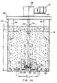
- FIG. 1A The flooding condition in a conventional gas dispersion system is shown in FIG. 1A.
- the sparge system is illustrated as a pipe 16, and may also be a ring or square pipe with openings at the top thereof.
- the sparge pipe 16 is disposed below the impeller.
- the gas flow predominates over the downward pumping action of the impeller. Strong geysers occur as shown at 17 and the holdup, U, over the ungassed height, Z, of the liquid in the tank is reduced.
- the holdup is a measure of how much the mixing system is holding the gas in the liquid and therefore is an indication of the mass transfer conversion potential.
- FIG. 1B where like parts and the parameters U and Z are identified by like letters and reference numerals.
- radial flow impellers have been used for gas dispersion when high gas rates are needed. Such impellers are disadvantageous for several reasons. They are less efficient in terms of the power level required to circulate the liquid in the tank (e.g., horsepower per 1000 gallons of liquid into which the gas is dispersed), than axial flow systems. Radial dispersion results in higher fluid shear rates than with axial flow impellers. High shear is undesirable for many processes, such as in some fermentations where shear sensitive microorganisms thrive in environments with low fluid shear rates.
- a significant disadvantage of radial flow gas dispersion systems is that the flow pattern is not principally axial but rather is radial and usually has two loops, one of which extends outwardly from the impeller towards the bottom of the tank and the other outwardly from the impeller towards the top of the tank. Such flow patterns are less desirable for solid suspension and blending than the single loop flow pattern characteristic of axial flow impellers.
- Incomplete dispersion is another drawback of radial flow systems.
- the classical radial flow system uses a Rushton type radial flow impeller with a sparge pipe or ring below the impeller.
- FIG. 1C A more advanced design is shown in FIG. 1C and utilizes a radial flow impeller system of the type described in Engelbrecht and Weetman, U.S.
- FIG. 1C This impeller system 20 with its radial flow impeller 22 and sparge ring 24 are diagrammatically shown in FIG. 1C.
- the liquid inlet to the impeller, which rotates about its vertical axis 25, is below the impeller 22 in the region shown at 26.
- the volume of the liquid below the impeller does not have any dispersion of gas and the gas dispersion does not extend to the bottom of the tank.
- approximately one-quarter of the total volume of the tank does not have a dispersion of gas. If the impeller is moved to higher elevations in the tank, this region without gas dispersion gets larger.
- the lower limit for the elevation of the impeller in the tank is limited because at the bottom the inlet region 26 becomes too small to support circulation. In a typical installation at less than one-half diameter elevation, the flow cannot make the turn into the region 26 and the power level drops abruptly. The mechanical loads on the mixer system then can increase. The dispersion capability thus breaks down when the radial flow impeller is located too close to the bottom of the tank.
- the volume of liquid in which the gas is dispersed is therefore smaller with a radial flow impeller than with an axial flow impeller, and for like gas rates, the holdup, U, and the mass conversion rate is less under many conditions in the radial flow than in the axial flow case.
- axial flow impellers have been limited in the gas rate which they can disperse because of the onset of the flooding condition. It has been suggested that radial flow impellers be used for gas dispersion in combination with axial flow impellers; thus an impeller having one or more axial flow impellers below which a radial flow impeller is mounted on the same shaft as the axial flow impellers have been proposed.
- An improved mixer system in accordance with this invention makes it possible to use an axial flow impeller as the primary gas dispersion impeller.
- the system may use one or more axial flow impellers mounted on the same shaft.
- the system has the ability to disperse gas and handle gas rates as high as or higher than radial flow impellers without severe flooding.
- the invention therefore allows the gas (when the term gas is mentioned, it shall be taken to include other fluids which are to be dispersed or sparged) with adequate dispersion and with the flow pattern for blending, solids suspension and efficiency which for axial flow impellers are more desirable or better for many applications than radial flow impellers.
- Another application where axial flow patterns are more desirable is heat transfer where the tank has a jacket or other heat exchanger in heat transfer relationship with the fluid in the tank.
- An open impeller is an impeller without a shroud or tube, such as a draft tube, which confines the flow pattern.
- the use of baffles along the walls of the tank does not constitute shrouding of the impeller.
- an apparatus for dispersing a fluid into a liquid which can have solids suspended therein said apparatus including a tank having a bottom and side walls which extend axially of said tank, an impeller for providing a flow pattern in a liquid in the tank, a drive for rotating said impeller, and a fluid outlet inside said tank, characterized in that the impeller is an open axial impeller creating a recirculating axial flow pattern having principally axial flow components upwardly and downwardly between the bottom of the tank and the level of the liquid therein and a radial flow component in the direction across the bottom of said tank toward the side walls thereof, the outlet flow from said impeller being a predominantly axial flow downwardly towards the bottom of said tank and a predominantly radial flow towards the side walls of said tank, and in that the fluid outlet is disposed outside the diameter (D) of said impeller and at an elevation above the bottom of the tank up to about 0.5D being thus in a region of said tank which extends between the bottom of said tank and said impeller
- a mixing system for dispensing a fluid, such as gas, into a liquid which can have solids suspended therein and which embodies the invention uses a tank having a bottom and sidewalls which extend axially of the tank.
- the tank contains the liquid which fills it to a level above the bottom of the tank.
- Impeller means are used which provide an axial flow pattern having principally axial components upwardly and downwardly between the bottom of the tank and the level of the liquid therein and a radial flow component in a direction across the bottom of the tank towards the sidewalls thereof.
- the outlet flow from the impeller is the axial flow downwardly towards the bottom of the tank and radially towards the sidewalls of the tank.
- Means such as a sparge device, are provided for releasing the fluid into the impeller outlet flow outside of where the outlet flow is principally axial and inside where the flow is predominantly radial. Then the fluid (gas in most cases) is unable to oppose the axial liquid flow.
- the gas or fluid (which may be a liquid) has a density less than the density into which the fluid is to be dispersed.
- the sparge device is in the region of the tank which extends between the bottom of the tank and the impeller and is located outside of the diameter of the impeller, preferably at an elevation which is about the same as the elevation of the bottom edges of the blades of the impeller.
- the elevation of the outlet of the sparge device is as low as it can practicably be based without blocking the radial flow across the bottom of the tank.
- An elevation of approximately one-tenth the diameter of the impeller (0.1D approximately) is presently preferred.
- the impeller itself may be located at an elevation of from 0.15D to 2.0D. In this connection, and throughout this specification, elevation is taken as the measurement from its centerline in a plane perpendicular to the axis of rotation of the impeller through the center of the impeller.
- the size of the tank is not critical. For tall tanks, several impellers may be mounted on the same shaft one above the other.
- the tank diameter, T may be in the range such that the ratio of D to T (D/T) is approximately from 0.1 to 0.6.
- Fluidfoil impellers operate by developing a pressure differential in the fluid across the impeller blades.
- the blades may stall or separate (the fluid not flowing along the suction surface of the blade) thereby reducing the pressure differential and the pumping effectiveness.
- gas is introduced into the tank the gas does collect on the suction side of the blades.
- These cavities of gas do increase until the entire suction surface of the blade can be filled with a gas cavity.
- As more gas is introduced the entire blade is enveloped in gas and therefore will not pump axially that is obtained by the pressure differential across the blade. Then flooding occurs.
- the outlet flow of the impeller shears the gas bubbles and produces the finer dispersion and the impeller is able to handle many times the amount of gas without flooding.
- the energy of the gas is not opposing the energy of the mixer by being underneath it as in a conventional system.
- the invention is of course not limited to any particular theory or mode of operation of the system as described and claimed herein.
- FIGS. 1A, 1B and 1C are diagrammatic views of gas dispersion impeller systems showing the gas dispersion capabilities thereof. These views are discussed above and are labeled "prior art”.
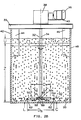
- FIGS. 2A and 2B are diagrammatic views of mixing systems in accordance with presently preferred embodiments of the invention; the system shown on FIG. 2A utilizing an axial flow impeller, type A315, which is available from Mixing Equipment Company, 135 Mount Read Boulevard, Rochester, New York, U.S. 14603 and which is described in the above identified Weetman Patent Application and FIG. 2B using an axial flow impeller which is of the Pitch blade turbine type, known as A200, also available from Mixing Equipment Company, and has four blades which are plates at 45° to the axis of rotation of the impeller.
- A315 which is available from Mixing Equipment Company, 135 Mount Read Boulevard, Rochester, New York, U.S. 14603 and which is described in the above identified Weetman Patent Application
- FIG. 2B using an axial flow impeller which is of the Pitch blade turbine type, known as A200, also available from Mixing Equipment Company, and has four blades which are plates at 45° to the axis of rotation of the impeller.
- FIGS. 3A and 3B are curves comparing three parameters, namely flood (the flooding condition point), holdup (U) and fluid force obtained with the system shown in FIGS. 2A and 2B, respectively, with a conventional axial flow gas dispersion system of the type shown in FIGS. 1A and 1B.
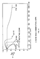
- FIG. 4 is a series of curves showing the relationship of K factor (relative power consumption or the ratio of the power consumption P g to P ug for the gassed and ungassed condition with impeller speed constant for several different types of impeller systems.
- K factor relative power consumption or the ratio of the power consumption P g to P ug for the gassed and ungassed condition with impeller speed constant for several different types of impeller systems.
- the curves show where the K factor drops which indicates the occurrence of the flooding condition.
- the curve for a Rushton type radial flow impeller is labeled R100.
- the curve for a system using a pitch blade turbine (PBT) with a rotating cone is labeled PBT with case.
- PBT pitch blade turbine
- the curve labeled A315 is for a conventional system, such as shown in FIGS. 1A and 1B (or with a sparge ring instead of a pipe sparge device utilizing an axial flow impeller of the A315 type as described in the above referenced Weetman U.S. Patent Application.
- the curve labeled FIG. 2A shows the K factor and the absence of any flooding condition well beyond the gas rate of any of the other systems identified in FIG. 4.
- FIG. 5 shows various embodiments of sparge rings which may be used in mixing systems in accordance with the invention.
- FIG. 6A and 6B are an elevation and a bottom view of another sparge device which may be used in accordance with the invention.
- FIG. 7 shows cross sectional views of different types of outlet ports which may be used in the sparge device shown in FIG. 6A and 6B; the sections shown in FIG. 7 being taken along the line 7-7 in FIG. 6B.
- FIGS. 2A and 2B there are shown diagrammatically mixing systems embodying the invention which are similar except for the impeller 30a in FIG. 2A and 30b in FIG. 2B.
- the impeller is of the A315 type having four blades in pairs diametrically opposite to each other. The blades are generally rectangular and have camber and twist which increases towards the shaft 32.
- the impeller 30b is a pitched blade turbine with four blades in diametrically opposed pairs. Each blade is a plate which is oriented at 45° to the axis of rotation of the impeller which is the axis 34 of the shaft 32.
- the illustrated pitched blade turbine 30b (PBT) is of the A200 type.
- the impeller is driven by a drive system consisting of a motor 36 and gearbox 38 which is mounted on a support, diagrammatically illustrated as beams 39 and 40, which are disposed over a tank 42 containing liquid with solid suspension.
- a drive system consisting of a motor 36 and gearbox 38 which is mounted on a support, diagrammatically illustrated as beams 39 and 40, which are disposed over a tank 42 containing liquid with solid suspension.
- the ungassed height Z and the holdup U are illustrated for the case where gas is completely dispersed.
- baffles two of which are indicated at 44 and 46 which extend radially inward from the sidewalls 48 of the tank 42.
- the bottom 50 of the tank may be flat.
- the bottom may be dished or contoured. When using a dished bottom, the elevations are measured along perpendiculars to the bottom to the point where the perpendiculars intersect the bottom.
- the baffles may be spaced 90° from each other circumferentially about the axis 34.
- the impellers 30a and 30b are designed to be downpumping with their pressure surfaces being the lower surfaces 55 of their blades 52 and the suction surfaces being the upper surfaces 54 of the blades.
- the blades have upper and lower edges indicated at 56 and 58.
- the diameter of the impeller between the tips of the blades (the swept diameter) is indicated as D.
- the impeller has a centerline 60 which is in a plane perpendicular to the axis 34 through the center of the impeller (halfway between the upper and lower edges 56 and 58).
- the elevation of the impeller above the bottom of the tank is measured between the centerline 60 and the bottom 50 of the tank and is indicated as C.
- the outlets for the gas are provided by circumferentially spaced apertures or openings 62 in a sparge ring 64.
- the distance between the sparge openings 62 and the bottom 50 of the tank is indicated as L. Where the bottom 50 is dished or contoured, L is the clearance.
- the distance between diametrically opposite openings 62 is the sparge diameter D s .
- D s is greater than D.
- D s is from about 1.3D to 1.4D.
- the preferred embodiment of the invention as shown in FIGS. 2A and 2B provides both the blades and the sparge device 64 at an elevation from the bottom of the tank so that the outlets 62 are in line with (in the same horizontal plane as) the lower edges 58 of the impeller 30.
- the principal advantage of the invention (higher gas rates before flooding) occur when the elevation L of the sparge opening 62 is about 0.5D or less.
- the preferred elevation is approximately 0.1D.
- L is approximately 0.094D and for FIG. 2B, L is 0.092D.
- C is approximately 0.26 and in FIG. 2B, C is approximately 0.17D.
- the A315 impeller diameter D of FIG. 2A is about 41.4 cm (16.3 inches) while the A200 of FIG. 2B is 40.4 cm (16.0 inches) in diameter.
- L is 3.81cm (1 1/2 inches) elevated from the bottom 50 of the tank 42.
- the openings 62 are at 180° where 0° is the top of the ring and parallel to the axis 32. In other words, the openings face downwardly.
- the elevation L of the sparge opening 62 may remain at approximately 0.1D but may extend upwardly to approximately 0.5D.
- the flooding condition onset occurs at greater gas rates when the openings 62 are in line with the lower edge 58 of the impeller blades and the elevation expressed as the ratio C/D is in the lower end of the range.
- the flow pattern is indicated by the arrows and has a single loop which, of course, is a torus with axial components extending upwardly and downwardly from the level of the liquid at the top of the tank to the bottom of the tank with a radial flow pattern at the bottom of the tank.
- the outlet flow from the impeller is the axial and the radial component at the bottom of the tank in FIGS 2A & B, the outlet flow is principally the radial component at the bottom of the tank.
- the sparge outlets 62 are disposed inside the radial outlet flow and outside the axial outlet flow. The radial flow shears the gas into fine bubbles which then are uniformly dispersed throughout the volume of the liquid in the tank.
- the axial flow pattern maintains solids in suspension.
- the power number N P which is equal to P/(rho)N3D5
- P is the power delivered to the impeller in watts
- (rho) is the density of the liquid (in kilograms per cubic meter)
- N is the impeller speed in revolutions per second
- D is the impeller diameter in meters (the diameter swept by the tips of the impeller blades).
- FIGS. 3A and 3B The new and surprising results obtained from the mixing system which is provided in accordance with the invention and specifically, the systems illustrated in FIGS. 2A and 2B, are illustrated in FIGS. 3A and 3B, respectively.
- the configuration of the system is with the sparge ring 64 as shown in FIGS. 2A and 2B at an elevation of approximately 0.09D above the bottom 50 of the tank 42.
- the elevation of the impeller in terms of the ratio C/D is varied and is shown on the X axis of the curve.
- the data in these curves was taken with the sparge ring 55.1 cm (21.7 inches) in diameter as measured at D s .
- Patent 4,527,905 for further information respecting fluid forces and methods of their measurement. It will be observed from FIG. 3A that the fluid forces are always less than that obtained in the conventional system over the entire C/D range. The flooding point occurs at gas rates from 1.6 to 4.8 times greater than for the conventional system. The holdup is also greater. For the A200 system (PBT) as shown in FIG. 3B, the fluid forces are not substantially affected over the range. However, the holdup and flooding condition points are improved to almost four times in the case of flooding and almost 2.8 times in the case of holdup.
- FIG. 4 Another way of looking at the point when the flooding condition occurs is by examination of the K factor.
- the striking superiority of the system provided in accordance with the invention is illustrated in FIG. 4.
- both the conventional Rushton and other types of conventional axial flow impeller systems are compared with the system shown in FIG. 2A.
- the flooding condition for the FIG. 2A system occurs at approximately 2.83 Standard m3/min. (100 SCFM).
- FIG. 5 illustrates various embodiments of the sparge ring 64.
- the ring shown in FIGS. 2A and 2B is illustrated in Part a of FIG. 5.
- the orientation of this ring may vary as shown in Parts e and f from 0° in f to 270° (inwardly towards the axis of rotation 34) in e.
- Part b shows a rectangular cross section for the ring which is one form of rectilinear cross section.
- Part c shows an elliptical cross section and Part d shows a triangular cross section with the opening 62 in the inside leg of the triangle.
- a sparge device in the form of a fork shaped pipe 70 with four ports or outlets in the form of pipe segments 74, 76, 78 and 80.
- the outlets are at the elevation L from the bottom 50 of the tank (FIG. 6A).
- the orientation is shown with respect to the axis of rotation 34.
- the segments may be open at the bottom and either flat (perpendicular to the axis 34) or angled or curved either inwardly or outwardly away from the axis.
- the segments may have a closed end cap with an outside hole as shown at 75 in FIG. 7D.
Landscapes
- Chemical & Material Sciences (AREA)
- Chemical Kinetics & Catalysis (AREA)
- Mixers Of The Rotary Stirring Type (AREA)
- Lubricants (AREA)
Claims (8)
- Vorrichtung zum Dispergieren eines Fluids in eine Flüssigkeit, in der Feststoffe suspendiert sein können, wobei die Vorrichtung folgendes umfaßt: einen Behälter (42) mit einem Boden (50) und Seitenwänden (48), die sich in axialer Richtung des Behälters erstrecken, einen Rührflügel (30a, 30b), der ein Strömungsmuster in einer in dem Behälter befindlichen Flüssigkeit erzeugt, einen Antrieb (36, 38), der den Rührflügel in Drehung versetzt, und einen in dem Behälter (42) befindlichen Fluidauslaß (62, 64), dadurch gekennzeichnet, daß der Rührflügel ein offener axial angeordneter Rührflügel ist, der ein wiederkehrendes axiales Strömungsmuster mit im wesentlichen axialen Strömungskomponenten, die zwischen dem Boden (50) des Behälters (42) und dem Pegel der darin befindlichen Flüssigkeit nach oben und nach unten verlaufen, und einer radialen Strömungskomponente in Richtung quer zum Boden des Behälters zu den Seitenwänden (48) hin erzeugt, wobei die von dem Rührflügel weggehende Strömung eine vorwiegend axiale, nach unten zum Boden des Behälters gerichtete Strömung und eine vorwiegend radiale Strömung in Richtung zu den Seitenwänden des Behälters ist, und daß der Fluidauslaß außerhalb des Durchmessers (D) des Rührflügels und in einer Höhe (L) über dem Boden (50) des Behälters (42) von bis zu etwa 0,5D angeordnet ist, so daß er sich in einem Bereich des Behälters befindet, der sich zwischen dem Boden des Behälters und dem Rührflügel erstreckt, um das Fluid in dem Auslaßstrom nach außen zu leiten, wo die Strömung in axialer Richtung verläuft, und nach innen, wo die Strömung in radialer Richtung verläuft, so daß das Fluid der axial nach außen gerichteten Strömung nicht entgegenwirken kann.
- Vorrichtung nach Anspruch 1, dadurch gekennzeichnet, daß der Rührflügel in einer Höhe C über dem Boden des Behälters von etwa 0,15D bis 2,0D angeordnet ist.
- Vorrichtung nach Anspruch 2, dadurch gekennzeichnet, daß sich die Höhe L des Fluidauslasses 0,1D über dem Boden des Behälters befindet, und daß der Fluidauslaß bei 1,3 bis 1,4R (

- Vorrichtung nach Anspruch 2, dadurch gekennzeichnet, daß der Fluidauslaß ein Rohr (64) ist mit einer Vielzahl von Auslaßöffnungen, die im Abstand voneinander um die Achse herum angeordnet sind.
- Vorrichtung nach Anspruch 4, dadurch gekennzeichnet, daß die Öffnungen Rohrsegmente sind, die sich von dem Rohr nach unten zum Boden des Behälters erstrecken, wobei die Öffnungen ausgewählt sind aus der Gruppe umfassend nach unten weisende Öffnungen am Ende der Segmente senkrecht zu der Achse, Öffnungen in den Seiten der Segmente gegenüber der Achse, und nach unten weisende Öffnungen, die zu der Achse hin geneigt sind.
- Vorrichtung nach Anspruch 4, dadurch gekennzeichnet, daß das Rohr ein Ring ist, dessen Mittelpunkt sich in etwa auf der Achse befindet, wobei der Ring einen Radius größer R besitzt, und die Auslaßöffnungen Öffnungen in dem Ring sind, die im Abstand voneinander um den Ring herum angeordnet sind.
- Vorrichtung nach Anspruch 1, dadurch gekennzeichnet, daß der Rührflügel eine Turbine mit schräggestellter Schaufel ist.
- Vorrichtung nach Anspruch 1, dadurch gekennzeichnet, daß die Rührflügel tragflächenartig ausgebildet sind.
Applications Claiming Priority (2)
| Application Number | Priority Date | Filing Date | Title |
|---|---|---|---|
| US209158 | 1988-06-20 | ||
| US07/209,158 US4882098A (en) | 1988-06-20 | 1988-06-20 | Mass transfer mixing system especially for gas dispersion in liquids or liquid suspensions |
Publications (3)
| Publication Number | Publication Date |
|---|---|
| EP0347618A2 EP0347618A2 (de) | 1989-12-27 |
| EP0347618A3 EP0347618A3 (de) | 1991-10-16 |
| EP0347618B1 true EP0347618B1 (de) | 1994-05-04 |
Family
ID=22777596
Family Applications (1)
| Application Number | Title | Priority Date | Filing Date |
|---|---|---|---|
| EP89109743A Expired - Lifetime EP0347618B1 (de) | 1988-06-20 | 1989-05-30 | Mischvorrichtung |
Country Status (11)
| Country | Link |
|---|---|
| US (1) | US4882098A (de) |
| EP (1) | EP0347618B1 (de) |
| AU (1) | AU607386B2 (de) |
| BR (1) | BR8906965A (de) |
| CA (1) | CA1290746C (de) |
| DE (1) | DE68915059T2 (de) |
| DK (1) | DK272589A (de) |
| IE (1) | IE64111B1 (de) |
| NO (1) | NO892314L (de) |
| WO (1) | WO1989012496A1 (de) |
| ZA (1) | ZA893885B (de) |
Cited By (4)
| Publication number | Priority date | Publication date | Assignee | Title |
|---|---|---|---|---|
| US8067645B2 (en) | 2005-05-20 | 2011-11-29 | Solvay (Societe Anonyme) | Process for producing a chlorhydrin from a multihydroxylated aliphatic hydrocarbon and/or ester thereof in the presence of metal salts |
| US8106246B2 (en) | 2005-11-08 | 2012-01-31 | Solvay (Societe Anonyme) | Process for the manufacture of dichloropropanol by chlorination of glycerol |
| US8106245B2 (en) | 2005-05-20 | 2012-01-31 | Solvay (Société Anonyme) | Method for preparing chlorohydrin by converting polyhydroxylated aliphatic hydrocarbons |
| US8415509B2 (en) | 2003-11-20 | 2013-04-09 | Solvay (Societe Anonyme) | Process for producing dichloropropanol from glycerol, the glycerol coming eventually from the conversion of animal fats in the manufacture of biodiesel |
Families Citing this family (32)
| Publication number | Priority date | Publication date | Assignee | Title |
|---|---|---|---|---|
| US5009796A (en) * | 1986-03-24 | 1991-04-23 | Robert Adler | Methods and apparatus for treating a mixture of particles and fluids |
| GB9101546D0 (en) * | 1990-02-05 | 1991-03-06 | Ici Plc | Agitators |
| US5152934A (en) * | 1991-04-08 | 1992-10-06 | General Signal Corp. | Mixing system for gas dispersion in liquids or liquid suspensions |
| US5261783A (en) * | 1991-12-09 | 1993-11-16 | U.S. Water Technologies, Inc. | Kinetic pump having a centerless impeller |
| US5845993A (en) * | 1995-10-12 | 1998-12-08 | The Dow Chemical Company | Shear mixing apparatus and use thereof |
| EP0976441A1 (de) * | 1998-07-31 | 2000-02-02 | Emmetre S.r.l. | Vorrichtung für die Belüftung von Wasser, Getränken und Flüssigkeiten im allgemeinem. |
| DE19836565A1 (de) * | 1998-08-12 | 2000-02-17 | Linde Ag | Verfahren und Vorrichtung zum Mischen von Produkten |
| US6158722A (en) * | 1998-09-23 | 2000-12-12 | General Signal Corporation | Mixing system for introducing and dispersing gas into liquids |
| US6250797B1 (en) * | 1998-10-01 | 2001-06-26 | General Signal Corporation | Mixing impeller system having blades with slots extending essentially all the way between tip and hub ends thereof which facilitate mass transfer |
| US6082890A (en) * | 1999-03-24 | 2000-07-04 | Pfaudler, Inc. | High axial flow glass coated impeller |
| FR2826296A1 (fr) * | 2001-06-22 | 2002-12-27 | Air Liquide | Dispositif de dissolution d'oxygene dans un liquide contenu dans un reacteur, procede de dissolution d'oxygene dans un liquide et procede d'amelioration d'un dispositif de dissolution d'oxygene dans un liquide |
| US6811296B2 (en) * | 2002-11-18 | 2004-11-02 | Spx Corporation | Aeration apparatus and method |
| US6877959B2 (en) * | 2003-06-03 | 2005-04-12 | Mixing & Mass Transfer Technologies, Llc | Surface aeration impellers |
| DE102006008687A1 (de) * | 2006-02-24 | 2007-08-30 | Bayer Technology Services Gmbh | Verfahren und Vorrichtung zur Be- und Entgasung von Flüssigkeiten |
| KR100979372B1 (ko) | 2006-06-14 | 2010-08-31 | 솔베이(소시에떼아노님) | 조 글리세롤계 생성물, 그 정제방법 및 디클로로프로판올의제조에의 그 용도 |
| DE602007014099D1 (de) * | 2007-01-02 | 2011-06-01 | Ge Healthcare Bio Sciences Ab | |
| DE102007001711A1 (de) * | 2007-01-11 | 2008-07-17 | EKATO Rühr- und Mischtechnik GmbH | Rühranordnung mit einem Rührorgan und einer Begasungseinrichtung |
| FR2913421B1 (fr) | 2007-03-07 | 2009-05-15 | Solvay | Procede de fabrication de dichloropropanol. |
| FR2913684B1 (fr) | 2007-03-14 | 2012-09-14 | Solvay | Procede de fabrication de dichloropropanol |
| TW200911740A (en) * | 2007-06-01 | 2009-03-16 | Solvay | Process for manufacturing a chlorohydrin |
| TW200911693A (en) | 2007-06-12 | 2009-03-16 | Solvay | Aqueous composition containing a salt, manufacturing process and use |
| TW200911773A (en) | 2007-06-12 | 2009-03-16 | Solvay | Epichlorohydrin, manufacturing process and use |
| WO2009032205A2 (en) | 2007-09-05 | 2009-03-12 | Ge Analytical Instruments, Inc. | Carbon measurement in aqueous samples using oxidation at elevated temperatures and pressures |
| US8715568B2 (en) | 2007-10-02 | 2014-05-06 | Solvay Sa | Use of compositions containing silicon for improving the corrosion resistance of vessels |
| FR2925045B1 (fr) | 2007-12-17 | 2012-02-24 | Solvay | Produit a base de glycerol, procede pour son obtention et son utilisation dans la fabrication de dichloropropanol |
| TWI478875B (zh) | 2008-01-31 | 2015-04-01 | Solvay | 使水性組成物中之有機物質降解之方法 |
| WO2009121853A1 (en) | 2008-04-03 | 2009-10-08 | Solvay (Société Anonyme) | Composition comprising glycerol, process for obtaining same and use thereof in the manufacture of dichloropropanol |
| FR2935968B1 (fr) | 2008-09-12 | 2010-09-10 | Solvay | Procede pour la purification de chlorure d'hydrogene |
| CN103261181A (zh) | 2010-09-30 | 2013-08-21 | 索尔维公司 | 天然来源的环氧氯丙烷的衍生物 |
| AU2013234754B2 (en) * | 2012-03-23 | 2017-08-31 | Ekato Ruhr- Und Mischtechnik Gmbh | System and method for starting up stirring machines in a sediment |
| JP6836151B2 (ja) * | 2017-01-25 | 2021-02-24 | 住友金属鉱山株式会社 | 加圧反応装置、及びそれを用いた有価金属の浸出処理方法 |
| JP6848507B2 (ja) * | 2017-02-17 | 2021-03-24 | 住友金属鉱山株式会社 | 加圧反応装置、及びそれを用いた有価金属の浸出処理方法 |
Family Cites Families (31)
| Publication number | Priority date | Publication date | Assignee | Title |
|---|---|---|---|---|
| GB190606062A (en) * | 1906-03-13 | 1906-10-18 | Alfred Z Clark | Improvements in Agitating Apparatus for use in Evaporating, Distilling, Emulsifying, Gas-washing, Pulping, and all similar Industrial Purposes. |
| US932221A (en) * | 1907-11-11 | 1909-08-24 | Richard Daryac Winship | Aerating agitator for liquids. |
| FR918726A (fr) * | 1945-12-11 | 1947-02-17 | Appareil pour traitement d'une solution liquide par un gaz | |
| US2521396A (en) * | 1945-12-22 | 1950-09-05 | Turbo Mixer Corp | Gas and liquid contact apparatus |
| BE505351A (de) * | 1950-08-23 | |||
| US2892543A (en) * | 1956-02-27 | 1959-06-30 | Mining Process & Patent Co | Aerator assembly with pulp elevating discharge |
| US2964382A (en) * | 1958-04-04 | 1960-12-13 | Wyandotte Chemicals Corp | Production of precipitated calcium carbonate |
| US3092678A (en) * | 1958-04-29 | 1963-06-04 | Vogelbusch Gmbh | Apparatus for gasifying liquids |
| US3227701A (en) * | 1962-05-29 | 1966-01-04 | Phillips Petroleum Co | Carboxylation and acidification of polymers |
| SE210328C1 (sv) * | 1962-08-03 | 1967-01-17 | Boliden Ab | Skumflotationsapparat |
| US3378141A (en) * | 1963-03-28 | 1968-04-16 | Res & Dev Pty Ltd | Froth flotation apparatus |
| US3202281A (en) * | 1964-10-01 | 1965-08-24 | Weston David | Method for the flotation of finely divided minerals |
| US3342331A (en) * | 1965-05-24 | 1967-09-19 | Maxwell John Russell | Flotation machine |
| US3288567A (en) * | 1965-08-25 | 1966-11-29 | Stratford Eng Corp | Floating catalyst bed contactor |
| FR90116E (fr) * | 1966-02-03 | 1967-10-20 | Fermentation S A Pour L Expl D | Procédé et dispositif d'agitation avec circulation méthodique de masses liquides par insufflation de gaz |
| US3464552A (en) * | 1967-12-18 | 1969-09-02 | Res & Dev Pty Ltd | Froth flotation apparatus |
| FR1580389A (de) * | 1968-07-03 | 1969-09-05 | ||
| US3628775A (en) * | 1969-02-14 | 1971-12-21 | Atara Corp | Sewage-treating system |
| US3814396A (en) * | 1972-02-16 | 1974-06-04 | Envirotech Corp | Aeration apparatus |
| US4207275A (en) * | 1974-03-29 | 1980-06-10 | General Signal Corporation | Mixing apparatus |
| US4066722A (en) * | 1976-05-21 | 1978-01-03 | Union Carbide Corporation | Apparatus for sparging gas into liquid |
| US4231974A (en) * | 1979-01-29 | 1980-11-04 | General Signal Corporation | Fluids mixing apparatus |
| US4247391A (en) * | 1979-03-09 | 1981-01-27 | Lloyd Philip J D | Froth flotation cell and method of operation |
| US4451373A (en) * | 1980-04-14 | 1984-05-29 | Water Pollution Control Corp. | Ring channel aeration apparatus and method |
| US4454078A (en) * | 1980-11-10 | 1984-06-12 | General Signal Corporation | Mixing systems having agitators for mixing gas with liquid |
| GB2106806B (en) * | 1981-10-02 | 1985-09-11 | Davy Mckee | Apparatus for separating particulate materials of different particle sizes |
| US4468130A (en) * | 1981-11-04 | 1984-08-28 | General Signal Corp. | Mixing apparatus |
| US4521349A (en) * | 1983-01-20 | 1985-06-04 | A. R. Wilfley And Sons, Inc. | Fluid diffuser for gases and liquids |
| GB2143440A (en) * | 1983-07-21 | 1985-02-13 | Morton Robert Dg Ltd | Mixers |
| US4527904A (en) * | 1984-06-12 | 1985-07-09 | General Signal Corporation | Measurement of fluid forces in mixing apparatus and the control of mixing apparatus in response to fluid forces |
| DE3442294A1 (de) * | 1984-11-20 | 1986-05-22 | Bertulies, Horst, 4600 Dortmund | Vorrichtung zum homogenisieren und suspensieren von feststofftrueben, insbesondere von schlaemmen fuer wirbelschichtfeuerungen |
-
1988
- 1988-06-20 US US07/209,158 patent/US4882098A/en not_active Expired - Fee Related
-
1989
- 1989-05-23 ZA ZA893885A patent/ZA893885B/xx unknown
- 1989-05-25 AU AU35152/89A patent/AU607386B2/en not_active Ceased
- 1989-05-30 EP EP89109743A patent/EP0347618B1/de not_active Expired - Lifetime
- 1989-05-30 DE DE68915059T patent/DE68915059T2/de not_active Expired - Fee Related
- 1989-06-01 CA CA000601388A patent/CA1290746C/en not_active Expired - Lifetime
- 1989-06-02 DK DK272589A patent/DK272589A/da not_active Application Discontinuation
- 1989-06-06 NO NO89892314A patent/NO892314L/no unknown
- 1989-06-19 IE IE198889A patent/IE64111B1/en not_active IP Right Cessation
- 1989-06-20 BR BR898906965A patent/BR8906965A/pt not_active Application Discontinuation
- 1989-06-20 WO PCT/US1989/002832 patent/WO1989012496A1/en not_active Ceased
Cited By (10)
| Publication number | Priority date | Publication date | Assignee | Title |
|---|---|---|---|---|
| US8415509B2 (en) | 2003-11-20 | 2013-04-09 | Solvay (Societe Anonyme) | Process for producing dichloropropanol from glycerol, the glycerol coming eventually from the conversion of animal fats in the manufacture of biodiesel |
| US8067645B2 (en) | 2005-05-20 | 2011-11-29 | Solvay (Societe Anonyme) | Process for producing a chlorhydrin from a multihydroxylated aliphatic hydrocarbon and/or ester thereof in the presence of metal salts |
| US8106245B2 (en) | 2005-05-20 | 2012-01-31 | Solvay (Société Anonyme) | Method for preparing chlorohydrin by converting polyhydroxylated aliphatic hydrocarbons |
| US8173823B2 (en) | 2005-05-20 | 2012-05-08 | Solvay (Société Anonyme) | Method for making an epoxide |
| US8344185B2 (en) | 2005-05-20 | 2013-01-01 | SOLVAY (Société Anonyme | Method for making a chlorhydrine by reaction between a polyhydroxylated aliphatic hydrocarbon and a chlorinating agent |
| US8389777B2 (en) | 2005-05-20 | 2013-03-05 | Solvay (Société Anonyme) | Continuous method for making chlorhydrines |
| US8420871B2 (en) | 2005-05-20 | 2013-04-16 | Solvay (Societe Anonyme) | Process for producing an organic compound |
| US8519198B2 (en) | 2005-05-20 | 2013-08-27 | Solvay (Societe Anonyme) | Method for making an epoxide |
| US8591766B2 (en) | 2005-05-20 | 2013-11-26 | Solvay (Societe Anonyme) | Continuous process for preparing chlorohydrins |
| US8106246B2 (en) | 2005-11-08 | 2012-01-31 | Solvay (Societe Anonyme) | Process for the manufacture of dichloropropanol by chlorination of glycerol |
Also Published As
| Publication number | Publication date |
|---|---|
| CA1290746C (en) | 1991-10-15 |
| DE68915059D1 (de) | 1994-06-09 |
| US4882098A (en) | 1989-11-21 |
| EP0347618A3 (de) | 1991-10-16 |
| IE891988L (en) | 1989-12-20 |
| NO892314L (no) | 1989-12-21 |
| EP0347618A2 (de) | 1989-12-27 |
| AU3515289A (en) | 1989-12-21 |
| DK272589A (da) | 1989-12-21 |
| AU607386B2 (en) | 1991-02-28 |
| WO1989012496A1 (en) | 1989-12-28 |
| ZA893885B (en) | 1990-05-30 |
| NO892314D0 (no) | 1989-06-06 |
| IE64111B1 (en) | 1995-07-12 |
| DK272589D0 (da) | 1989-06-02 |
| DE68915059T2 (de) | 1994-11-03 |
| BR8906965A (pt) | 1990-12-11 |
Similar Documents
| Publication | Publication Date | Title |
|---|---|---|
| EP0347618B1 (de) | Mischvorrichtung | |
| US5198156A (en) | Agitators | |
| EP0880993B1 (de) | Rührschaufelanordnung mit asymmetrisch-konkaven Schaufeln | |
| US4305673A (en) | High efficiency mixing impeller | |
| JP3677227B2 (ja) | 攪拌翼および攪拌方法 | |
| WO2017185431A1 (zh) | 一种装配扇环型凹面叶片的气液分散搅拌器装置 | |
| US6158722A (en) | Mixing system for introducing and dispersing gas into liquids | |
| JPS6253213B2 (de) | ||
| CA2035141A1 (en) | Agitators | |
| US5525269A (en) | Impeller tiplets for improving gas to liquid mass transfer efficiency in a draft tube submerged turbine mixer/aerator | |
| US7934867B2 (en) | Stirring apparatus | |
| EP0234768B1 (de) | Rührer | |
| HK1001041B (en) | Agitator | |
| US6149296A (en) | Mixer blade assembly for medium and high viscosity liquid | |
| US4074953A (en) | Surface aerator | |
| EP0027911B1 (de) | Vorrichtung zum Begasen einer Flüssigkeit | |
| US4421414A (en) | High efficiency mixing method | |
| JPH08281089A (ja) | 竪形撹拌機 | |
| US3149823A (en) | Impeller | |
| JP2006043668A (ja) | 流体撹拌装置、それに用いるタービン型撹拌機及び邪魔板 | |
| GB2068247A (en) | Mixing apparatus with rotary agitator | |
| US5152934A (en) | Mixing system for gas dispersion in liquids or liquid suspensions | |
| SU889076A1 (ru) | Мешалка | |
| GB2312174A (en) | Agitator impeller having hydrofoil blades with a swept back trailing edge | |
| SU799802A1 (ru) | Турбинна мешалка |
Legal Events
| Date | Code | Title | Description |
|---|---|---|---|
| PUAI | Public reference made under article 153(3) epc to a published international application that has entered the european phase |
Free format text: ORIGINAL CODE: 0009012 |
|
| AK | Designated contracting states |
Kind code of ref document: A2 Designated state(s): BE DE ES FR GB IT LU SE |
|
| 17P | Request for examination filed |
Effective date: 19901213 |
|
| PUAL | Search report despatched |
Free format text: ORIGINAL CODE: 0009013 |
|
| AK | Designated contracting states |
Kind code of ref document: A3 Designated state(s): BE DE ES FR GB IT LU SE |
|
| 17Q | First examination report despatched |
Effective date: 19920416 |
|
| GRAA | (expected) grant |
Free format text: ORIGINAL CODE: 0009210 |
|
| AK | Designated contracting states |
Kind code of ref document: B1 Designated state(s): BE DE ES FR GB IT LU SE |
|
| PG25 | Lapsed in a contracting state [announced via postgrant information from national office to epo] |
Ref country code: SE Free format text: THE PATENT HAS BEEN ANNULLED BY A DECISION OF A NATIONAL AUTHORITY Effective date: 19940504 Ref country code: FR Effective date: 19940504 Ref country code: ES Free format text: THE PATENT HAS BEEN ANNULLED BY A DECISION OF A NATIONAL AUTHORITY Effective date: 19940504 Ref country code: BE Effective date: 19940504 Ref country code: IT Free format text: LAPSE BECAUSE OF FAILURE TO SUBMIT A TRANSLATION OF THE DESCRIPTION OR TO PAY THE FEE WITHIN THE PRESCRIBED TIME-LIMIT;WARNING: LAPSES OF ITALIAN PATENTS WITH EFFECTIVE DATE BEFORE 2007 MAY HAVE OCCURRED AT ANY TIME BEFORE 2007. THE CORRECT EFFECTIVE DATE MAY BE DIFFERENT FROM THE ONE RECORDED. Effective date: 19940504 |
|
| PG25 | Lapsed in a contracting state [announced via postgrant information from national office to epo] |
Ref country code: LU Free format text: LAPSE BECAUSE OF NON-PAYMENT OF DUE FEES Effective date: 19940531 |
|
| REF | Corresponds to: |
Ref document number: 68915059 Country of ref document: DE Date of ref document: 19940609 |
|
| EN | Fr: translation not filed | ||
| PLBE | No opposition filed within time limit |
Free format text: ORIGINAL CODE: 0009261 |
|
| STAA | Information on the status of an ep patent application or granted ep patent |
Free format text: STATUS: NO OPPOSITION FILED WITHIN TIME LIMIT |
|
| PGFP | Annual fee paid to national office [announced via postgrant information from national office to epo] |
Ref country code: GB Payment date: 19950424 Year of fee payment: 7 |
|
| 26N | No opposition filed | ||
| PGFP | Annual fee paid to national office [announced via postgrant information from national office to epo] |
Ref country code: DE Payment date: 19960418 Year of fee payment: 8 |
|
| PG25 | Lapsed in a contracting state [announced via postgrant information from national office to epo] |
Ref country code: GB Effective date: 19960530 |
|
| GBPC | Gb: european patent ceased through non-payment of renewal fee |
Effective date: 19960530 |
|
| PG25 | Lapsed in a contracting state [announced via postgrant information from national office to epo] |
Ref country code: DE Free format text: LAPSE BECAUSE OF NON-PAYMENT OF DUE FEES Effective date: 19980203 |