EP0347585B1 - Uebergangs-Regelsystem zur Lageregelung eines Raumfahrzeuges - Google Patents
Uebergangs-Regelsystem zur Lageregelung eines Raumfahrzeuges Download PDFInfo
- Publication number
- EP0347585B1 EP0347585B1 EP89108978A EP89108978A EP0347585B1 EP 0347585 B1 EP0347585 B1 EP 0347585B1 EP 89108978 A EP89108978 A EP 89108978A EP 89108978 A EP89108978 A EP 89108978A EP 0347585 B1 EP0347585 B1 EP 0347585B1
- Authority
- EP
- European Patent Office
- Prior art keywords
- spacecraft
- roll
- yaw
- nutation
- angle
- Prior art date
- Legal status (The legal status is an assumption and is not a legal conclusion. Google has not performed a legal analysis and makes no representation as to the accuracy of the status listed.)
- Expired - Lifetime
Links
Images

Classifications
-
- G—PHYSICS
- G09—EDUCATION; CRYPTOGRAPHY; DISPLAY; ADVERTISING; SEALS
- G09B—EDUCATIONAL OR DEMONSTRATION APPLIANCES; APPLIANCES FOR TEACHING, OR COMMUNICATING WITH, THE BLIND, DEAF OR MUTE; MODELS; PLANETARIA; GLOBES; MAPS; DIAGRAMS
- G09B9/00—Simulators for teaching or training purposes
- G09B9/02—Simulators for teaching or training purposes for teaching control of vehicles or other craft
- G09B9/52—Simulators for teaching or training purposes for teaching control of vehicles or other craft for teaching control of an outer space vehicle
-
- B—PERFORMING OPERATIONS; TRANSPORTING
- B64—AIRCRAFT; AVIATION; COSMONAUTICS
- B64G—COSMONAUTICS; VEHICLES OR EQUIPMENT THEREFOR
- B64G1/00—Cosmonautic vehicles
- B64G1/22—Parts of, or equipment specially adapted for fitting in or to, cosmonautic vehicles
- B64G1/24—Guiding or controlling apparatus, e.g. for attitude control
- B64G1/244—Spacecraft control systems
-
- B—PERFORMING OPERATIONS; TRANSPORTING
- B64—AIRCRAFT; AVIATION; COSMONAUTICS
- B64G—COSMONAUTICS; VEHICLES OR EQUIPMENT THEREFOR
- B64G1/00—Cosmonautic vehicles
- B64G1/22—Parts of, or equipment specially adapted for fitting in or to, cosmonautic vehicles
- B64G1/24—Guiding or controlling apparatus, e.g. for attitude control
- B64G1/26—Guiding or controlling apparatus, e.g. for attitude control using jets
-
- B—PERFORMING OPERATIONS; TRANSPORTING
- B64—AIRCRAFT; AVIATION; COSMONAUTICS
- B64G—COSMONAUTICS; VEHICLES OR EQUIPMENT THEREFOR
- B64G1/00—Cosmonautic vehicles
- B64G1/22—Parts of, or equipment specially adapted for fitting in or to, cosmonautic vehicles
- B64G1/24—Guiding or controlling apparatus, e.g. for attitude control
- B64G1/28—Guiding or controlling apparatus, e.g. for attitude control using inertia or gyro effect
- B64G1/285—Guiding or controlling apparatus, e.g. for attitude control using inertia or gyro effect using momentum wheels
-
- B—PERFORMING OPERATIONS; TRANSPORTING
- B64—AIRCRAFT; AVIATION; COSMONAUTICS
- B64G—COSMONAUTICS; VEHICLES OR EQUIPMENT THEREFOR
- B64G1/00—Cosmonautic vehicles
- B64G1/22—Parts of, or equipment specially adapted for fitting in or to, cosmonautic vehicles
- B64G1/24—Guiding or controlling apparatus, e.g. for attitude control
- B64G1/38—Guiding or controlling apparatus, e.g. for attitude control damping of oscillations, e.g. nutation dampers
Definitions
- This invention relates to attitude control systems for three-axis stabilized spacecraft. More specifically, the invention relates to controlling transition from thruster control to momentum wheel control in a momentum-bias three-axis stabilized geosynchronous spacecraft.
- One of the tasks in a spacecraft having a momentum-bias attitude control system is control of the transition from a high-authority control mode, such as that used for station-keeping maneuvers, with its relatively high angular rates, to a low-authority control mode, which relies on a momentum-bias attitude control system using for example a momentum wheel.
- the transition from the station-keeping mode to on-orbit mode must be performed carefully to avoid saturation and possibly loss of attitude control in the low-authority on-orbit control mode, since the high angular rates prior to transition can cause large nutation.
- the desired control accuracy of a three-axis stabilized spacecraft is 0.01 degrees to 0.05 degrees, exclusive of pointing error due to misalignments and structural or thermal distortion.
- the typical uncorrected attitude error following a station-keeping maneuver is a nutation circle with a radius on the order of twenty-five times greater, i.e., 0.25 degrees to 1.25 degrees.
- nutation amplitude must be sharply reduced, and preferably reduced to zero, before control is passed to the momentum-wheel-based on-orbit controller.
- nutation correction systems are open-loop control systems based on calculation, rather than measurement, of critical parameters. Respecting nutation control systems, the following patents were uncovered in a search of the public records of the U.S. Patent and Trademark Office.
- U.S. Patent No. 3,866,025 discloses a spacecraft attitude control system for producing thruster firings which align the total angular momentum vector with the desired orbit normal vector while simultaneously adjusting orbit.
- the invention employs a commonly-available sensor and thruster system. However, it seeks to perform an orbit adjustment maneuver in a manner that is intended to minimize build-up of nutation during the maneuver, rather than provide a mechanism for correction following the maneuver.
- the control system computes angular rates rather than directly sensing the rates.
- the patent is silent about the specific transition attitude control techniques of the present invention.
- the Johnson, Jr. patent pertains to a spin-stabilized spacecraft, rather than a three-axis stabilized spacecraft as described herein. It attempts to keep the nutation angle bounded, but it fails to suggest how to reduce nutation to zero.
- the Johansen patent describes an attitude control system for a three-axis stabilized spacecraft. It lacks any mechanism for sensing yarn angle, yaw angular rate, and roll angular rate.
- the Becker patent concerns spacecraft without internal momentum wheel control and therefore is not affected by nutation.
- the Fleming patent concerns the damping of a nutation circle by means of two thruster firings which are based on sensing the spacecraft roll angle only. There are no means for sensing roll, yaw, and yaw angular rates. As a consequence there can be no assurance of stability.
- the Phillips patent, the Pistener patent and the Amieux patent relate to spin-stabilized spacecraft, not three-axis stabilized spaceccraft and are not relevant to the invention.
- the Bruederle et al. patent pertains to attitude control of a three-axis stabilized spacecraft, but does not address the isssues of nutation control and transition from the thruster control mode to the wheel control mode. There are no sensors for yaw angle or yaw angular rates.
- the Nilsen patent discloses a PWPF system for attitude control which generates a series of pulses of varying frequency and width and shows the features of the first part of claims 1 and 7.
- the Hubert et al. patent concerns simultaneously precessing and nutation damping a spinning space craft rather than an attitude control system for a three-axis stabilized space craft. Nor is disclosed the transition from thruster control to momentum wheel control.
- the problem to be solved by invention is to sharply reduce the nutation amplitude, before control is passed to the momentum-wheel-based controller.
- a method for controlling transition from thruster control to momentum-wheel control to minimize nutation angle and transition time in a three-axis stabilized spacecraft employing an internal body fixed-momentum wheel as an attitude stabilizer.
- the method employs direct, substantially real-time measurement of momentum components and angular rates and generates paired thrust impulses in synchronization with the nutation period of the spacecraft.
- the nutation is driven to zero in one-half nutation period.
- the controller employs a deadbeat principle in a closed-loop real-time feedback system.
- the impulsive thruster firing commands in roll and yaw are simultaneous, spaced one-half nutation period apart in time with the effect that the spacecraft transverse momentum is reduced to an acceptably low level in three or fewer successive pairs of thruster impulse firings.
- the invention provides, with minimum transient overshoot, automatic reduction of angular momentum relative to a desired on-orbit state to a level which can be managed by a low-authority momentum wheel controller.
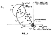
- Figure 1 is a vector diagram illustrating reduction of transverse momentum by deadbeat impulse firing control of a three-axis stabilized spacecraft wherein nutation circles, representing either circles or ellipses are shown for simplicity.
- FIG. 2 is a schematic diagram of a momentum control system for a spacecraft in accordance with the invention.
- Figure 1 is a vector diagram 10 of a spacecraft which illustrates nutation circles or in general ellipses relative to a set of transverse (roll/yaw) momentum axis.
- the body and structure of the spacecraft itself are not shown in the figures.
- One of the purposes of the invention is to minimize nutation and ideally reduce nutation of a spacecraft to zero.
- Figure 1 illustrates the effects of appropriate angular impulse correction in accordance with the invention.
- the change in momentum, a vector, ⁇ H of the spacecraft is equal to the product of the torque, a vector, T and the firing time t of the thrusters.
- the firing time is on the order of 40ms to 50ms, whereas the nutation period 1/ ⁇ , i.e., the time for a body to nutate through an entire nutation circle, is on the order of 150-300 seconds or longer.
- the long nutation period justifies any approximations related to impulsive firing.
- the nutation period is a function of the inertia of the spacecraft I s c and the wheel momentum of the spacecraft momentum wheel H w .
- up to three firings have been found to be necessary to reduce nutation to zero.
- FIG. 2 illustrates schematically a control system 30 in accordance with the invention.
- the spacecraft is represented figuratively by spacecraft dynamics 32.
- Spacecraft dynamics 32 produce as output parameters the motions of the spacecraft, the direction and sense of which are measured by a digital integrating rate assembly (DIRA) 34, which is a spacecraft-based gyroscope, and by an earth sensor 36.
- DIRA digital integrating rate assembly
- a roll signal ⁇ is provided via on roll signal line 38 to an onboard error calculator 40 from the earth sensor 36.
- the DIRA provides as output a yaw signal ⁇ on yaw signal line 42, a yaw rate signal on yaw rate signal line 44 and a roll rate signal ⁇ on roll rate signal line 46 to the onboard error calculator 40.
- the onboard error calculator 40 computes from these measured parameters, as hereinafter explained, the preliminary values for roll error e x and the preliminary values for yaw error e z and provides these signals via signal lines 48 and 50, or their equivalent, to noise filter means 52 and 54.
- the noise filter means 52 and 54 are basically low-pass filters whose function is to filter out high frequency rate noise from the roll and yaw error signals due to measurement errors and structural flexibility effects in the spacecraft.
- the output signal of the first noise filter 52 is the roll error signal ê x on signal line 56
- the output signal of the second noise filter 54 is the roll error signal ê z on signal line 58.
- the two error signals are weighted by values which for these purposes are constant, namely, the roll inertia component I x divided by the transverse roll torque component T cx 60, and the yaw inertia component I z divided by the transverse yaw torque component T cz 62.
- the output signals 64, 66 are applied to a timer 68 which uses them to control the impulse period for the respective roll thrusters 70 and yaw thrusters 72.
- the thrusters 70 and 72 apply torques T cx (roll torque) and T cz (yaw torque) to the spacecraft, which in turn is reflected in modified spacecraft dynamics 32. Thruster firing causes a change in the center of nutation.
- the applied torques reduce the transverse momentum toward zero and the nutation center toward zero yaw and roll in paired, or deadbeat, thruster firings whose duration and vector are determined by the measured roll, yaw, roll rate, and yaw rate.
- Pitch is not a factor in nutation correction, since pitch control is independent of roll and yaw.
- pitch control is independent of roll and yaw.
Landscapes
- Engineering & Computer Science (AREA)
- Remote Sensing (AREA)
- Aviation & Aerospace Engineering (AREA)
- Chemical & Material Sciences (AREA)
- Combustion & Propulsion (AREA)
- Radar, Positioning & Navigation (AREA)
- Theoretical Computer Science (AREA)
- Business, Economics & Management (AREA)
- Physics & Mathematics (AREA)
- Educational Administration (AREA)
- Educational Technology (AREA)
- General Physics & Mathematics (AREA)
- Automation & Control Theory (AREA)
- Control Of Position, Course, Altitude, Or Attitude Of Moving Bodies (AREA)
Claims (8)
- Verfahren zur Regelung des Übergangs von der Schubregelung zur Stabilisierungsschwungradregelung zur Minimalisierung des Nutationswinkels des Raumfahrzeugs und der Übergangszeit in einem dreiachsig stabilisierten Raumfahrzeug unter Verwendung eines internen, am Rumpf festgelegten Schwungrades als Lagestabilisierungsmittel und mit einer Nutationsperiode und einer entsprechenden Nutationsfrequenz,
mit folgenden Schritten:a) es werden gemessene Werte (38, 42, 44, 46) gebildet, die für den Rollwinkel (φ), dem Gierwinkel (ψ), die Rollgeschwindigkeit (φ̇) und die Giergeschwindigkeit (ψ̇) des Raumfahrzeugs repräsenativ sind,gekennzeichnet durchb) ein Quer-Drehimpulsvektor des Raumfahrzeugs (Δh1, Δh2 ...) wird aus den Trägheitsmomenten des Raumfahrzeugs (Is) und den genannten Werten (38, 42, 44, 46) errechnet, die für den Rollwinkel (φ), den Gierwinkel (ψ), die Rollgeschwindigkeit (φ̇) und die Giergeschwindigkeit (ψ̇) des Raumfahrzeugs repräsentativ sind, wobei der Quer-Drehimpulsvektor (Δh1, Δh2 ...) eine Rollkomponente (Δhx) und eine Gierkomponente (Δhz) aufweisen,c) aus den für den Rollwinkel (φ), den Gierwinkel (ψ), die Rollgeschwindigkeit (φ̇) und die Giergeschwindigkeit (ψ̇) repräsentativen Werte (38, 42, 44, 46) wird eine einzelne Zünddauer für jeden Lageregelungsschuberzeuger (70, 72) eines Satzes errechnet, um die Raumfahrzeugbewegung nachfolgend dem Zünden der Schuberzeuger dazu zu bringen, die Nutationsamplitude in Richtung auf einen Quer-Drehimpuls von Null zu reduzieren;d) der Satz der Lageregelungsschuberzeuger (70, 72) wird gemäß der errechneten einzelnen Zünddauer betrieben unde) die Schritte a) bis d) werden mindestens einmal in einem Intervall von im wesentlichen der Hälfte der Nutationsperiode des Raumfahrzeugs wiederholt. - Verfahren nach Anspruch 1,
gekennzeichnet durch den Schritt der Beseitigung (52, 54) von Störsignalen, die im wesentlichen oberhalb einer Nutationsfrequenz des Raumfahrzeuges liegen. - Verfahren nach Anspruch 1,
gekennzeichnet durch den weiteren Schritt der Errechnung der Nutationsperiode (2π/λ) aus der gemessenen Drehgeschwindigkeit des Schwungrades und aus Trägheitsmomenten des Schwungrades und des Raumfahrzeugs. - Verfahren nach einem der Ansprüche 1 bis 3,
dadurch gekennzeichnet, daß der Wiederholungsschritt (e) auf eine vorbestimmte Anzahl von Wiederholungen beschränkt wird. - Verfahren nach einem der Ansprüche 1 bis 3,
dadurch gekennzeichnet, daß der Wiederholungsschritt beendet wird, wenn die Größe des Quer-Drehimpulses unmittelbar nachfolgend dem Zündschritt unterhalb eines vorgewählten Wertes ist. - Verfahren nach einem der Ansprüche 2 bis 5,
dadurch gekennzeichnet, daß die Schuberzeuger im rechten Winkel zueinander angeordnet sind und daß der Zündschritt die gleichzeitige Zündung zur Regelung des Rollens und des Gierens einschließt. - Dreiachsig stabilisiertes Raumfahrzeug, welches eine Nutationsperiode zeigt und ein internes, am Rumpf festgelegtes Schwungrad als Lagestabilisierungsmittel verwendet und ein Gerät zur Regelung des Übergangs von Schubregelung auf Schwungradregelung zur Kleinhaltung des Nutationswinkels und der Übergangszeit aufweist,
mit folgenden Merkmalen:
eine Sensoreinrichtung (34, 36) zum Erhalt von gemessenen Werten (38, 42, 44, 46), die für den Rollwinkel (φ), den Gierwinkel (ψ), die Rollgeschwindigkeit (φ̇) und die Giergeschwindigkeit (ψ̇) des Raumfahrzeugs kennzeichnend sind und
eine mit der Abtasteinrichtung gekoppelte Einrichtung (30) zur Steuerung des Betriebs der Schuberzeuger für Roll- und Gierlagestabilisierungsregelung,
dadurch gekennzeichnet,
daß die Einrichtungen (30) zur Regelung in Intervallen von im wesentlichen einer Hälfte der Nutationsperiode ausgebildet sind und aufweisen:
eine Einrichtung (60, 62) zur Errechnung eines Quer-Drehimpulsvektors (Δh1, Δh2 ...) des Raumfahrzeugs in Intervallen von einer Hälfte der Nutationsperiode aus dem Trägheitsmoment des Raumfahrzeuges und den für Rollwinkel, Gierwinkel, Rollgeschwindigkeit und
Giergeschwindigkeit repräsentativen Werten, wobei der Quer-Drehimpulsvektor (Δh1, Δh2 ...) eine Rollkomponente (Δhx) und eine Gierkomponente (Δhz) aufweist,
eine Einrichtung (68) zur Errechnung einer einzelnen Zünddauer der Lageregelungsschuberzeuger (70, 72) aus den für Rollwinkel, Gierwinkel, Rollgeschwindigkelt und Giergeschwindigkeit repräsentativen Werten, um die Raumfahrzeugbewegung nachfolgend der Zündung der Schuberzeuger dazu zu bringen, die Nutationsamplitude in Richtung auf einen Quer-Drehimpuls von Null zu bringen,
eine Einrichtung zur Veranlassung einer einzelnen Zündung der Roll- und Gierlageregelungsschuberzeuger gemäß der Zünddauer und
eine Taktgebereinrichtung (68) zur Reihenbildung einer einzelnen Zündung der Roll- und Gierlagesteuerungsschuberzeuger (70, 72) in Intervallen von im wesentlichen einer Hälfte der Nutationsperiode des Raumfahrzeugs. - Gerät nach Anspruch 7,
gekennzeichnet durch eine Filtereinrichtung (52, 54), die zwischen der Abtasteinrichtung (34, 36) und der Steuereinrichtung (70, 72) angeordnet ist, wobei die Filtereinrichtung zur Beseitigung von Störsignalen im wesentlichen oberhalb einer Nutationsfrequenz des Raumfahrzeuges dient.
Applications Claiming Priority (2)
| Application Number | Priority Date | Filing Date | Title |
|---|---|---|---|
| US198942 | 1988-05-26 | ||
| US07/198,942 US4931942A (en) | 1988-05-26 | 1988-05-26 | Transition control system for spacecraft attitude control |
Publications (2)
| Publication Number | Publication Date |
|---|---|
| EP0347585A1 EP0347585A1 (de) | 1989-12-27 |
| EP0347585B1 true EP0347585B1 (de) | 1993-07-14 |
Family
ID=22735539
Family Applications (1)
| Application Number | Title | Priority Date | Filing Date |
|---|---|---|---|
| EP89108978A Expired - Lifetime EP0347585B1 (de) | 1988-05-26 | 1989-05-18 | Uebergangs-Regelsystem zur Lageregelung eines Raumfahrzeuges |
Country Status (5)
| Country | Link |
|---|---|
| US (1) | US4931942A (de) |
| EP (1) | EP0347585B1 (de) |
| JP (1) | JP2914998B2 (de) |
| CA (1) | CA1329246C (de) |
| DE (1) | DE68907528T2 (de) |
Families Citing this family (27)
| Publication number | Priority date | Publication date | Assignee | Title |
|---|---|---|---|---|
| DE3935609C1 (de) * | 1989-10-26 | 1990-12-13 | Messerschmitt-Boelkow-Blohm Gmbh, 8012 Ottobrunn, De | |
| US5098041A (en) * | 1990-06-07 | 1992-03-24 | Hughes Aircraft Company | Attitude control system for momentum-biased spacecraft |
| US5222023A (en) * | 1991-04-02 | 1993-06-22 | Space Systems/Loral, Inc. | Compensated transition for spacecraft attitude control |
| US5349532A (en) * | 1992-04-28 | 1994-09-20 | Space Systems/Loral | Spacecraft attitude control and momentum unloading using gimballed and throttled thrusters |
| US5608634A (en) * | 1992-06-12 | 1997-03-04 | Martin Marietta Corp. | Low noise spacecraft body rate sensing arrangement for attitude control |
| US5395076A (en) * | 1993-03-19 | 1995-03-07 | Martin Marietta Corporation | Spacecraft velocity change maneuvers by variable arcjets |
| US5459669A (en) * | 1994-02-14 | 1995-10-17 | Space Systems/Loral, Inc. | Control system and method for spacecraft attitude control |
| US5556058A (en) * | 1994-05-16 | 1996-09-17 | Hughes Electronics | Spacecraft attitude determination using sun sensor, earth sensor, and space-to-ground link |
| US6439509B1 (en) * | 1995-07-03 | 2002-08-27 | Space Systems/Loral, Inc. | Pre-bias scheme for roll momentum unloads on pitch momentum bias/yaw reaction wheel spacecraft |
| US5655735A (en) * | 1995-07-03 | 1997-08-12 | Space Systems Loral, Inc. | Post transition momentum management |
| US5752675A (en) * | 1995-07-03 | 1998-05-19 | Space Systems/Loral, Inc. | Thruster control of yaw without yaw measurements |
| US5787368A (en) * | 1995-11-03 | 1998-07-28 | Space Systems/Loral, Inc. | Spacecraft yaw control using only wheel speed measurements processed through a simple filter bank |
| US5996942A (en) | 1996-10-16 | 1999-12-07 | Space Systems/Loral, Inc. | Autonomous solar torque management |
| US6068217A (en) * | 1996-10-16 | 2000-05-30 | Space Systems/Loral, Inc. | Method to reorient a spacecraft using only initial single axis attitude knowledge |
| US6000661A (en) * | 1996-10-16 | 1999-12-14 | Space Systems/Loral, Inc. | Autonomous spacecraft payload base motion estimation and correction |
| US6023291A (en) * | 1996-10-16 | 2000-02-08 | Space Systems/Loral, Inc. | Satellite camera attitude determination and image navigation by means of earth edge and landmark measurement |
| US5935176A (en) * | 1996-11-22 | 1999-08-10 | Lockheed Martin Corporation | Momentum wheel oscillation filter |
| WO1998032657A1 (en) | 1997-01-27 | 1998-07-30 | Space Systems/Loral, Inc. | Spacecraft attitude control system using low thrust thrusters |
| US5957411A (en) * | 1997-01-31 | 1999-09-28 | Space Systems/Loral, Inc. | Method using double thruster firings to deadbeat flexible solar array structural oscillations |
| US6347262B1 (en) * | 2000-01-05 | 2002-02-12 | Hughes Electronics Corporation | Minimum fuel attitude and nutation controller for spinning spacecraft |
| US20060079922A1 (en) * | 2004-10-12 | 2006-04-13 | Brian Creston | Balloon anchored surgical apparatus, its use and manufacture |
| CN100393585C (zh) * | 2006-04-30 | 2008-06-11 | 哈尔滨工业大学 | 应用借力机制选择星际探测目标的探测器发射方法 |
| KR100837138B1 (ko) | 2006-07-18 | 2008-06-11 | 한국과학기술원 | 인공위성 자세 제어 명령 분배를 위한 동적 제어 할당 방법 |
| US8352101B2 (en) * | 2009-12-22 | 2013-01-08 | The Boeing Company | Algorithm for simultaneous attitude maneuver and momentum dumping |
| CN102923323B (zh) * | 2012-11-29 | 2014-12-31 | 北京理工大学 | 基于不变流形的行星际固定轨道间低能量转移设计方法 |
| CN102923322A (zh) * | 2012-11-29 | 2013-02-13 | 北京理工大学 | 一种基于等高线图的天体探测借力天体选择方法 |
| CN103303496B (zh) * | 2013-06-28 | 2015-09-09 | 上海新跃仪表厂 | 一种微幅调整轨道高度的方法 |
Family Cites Families (23)
| Publication number | Priority date | Publication date | Assignee | Title |
|---|---|---|---|---|
| US3643897A (en) * | 1968-10-18 | 1972-02-22 | Communications Satellite Corp | Nutation correction system for spin-stabilized satellite |
| US3866025A (en) * | 1972-03-17 | 1975-02-11 | Rca Corp | Spacecraft attitude control system |
| US3944172A (en) * | 1972-04-14 | 1976-03-16 | Erno Raumfahrttechnik Gmbh | Attitude control for space vehicle |
| US3813067A (en) * | 1972-06-29 | 1974-05-28 | Trw Inc | Attitude stabilization system |
| US3997137A (en) * | 1973-12-10 | 1976-12-14 | Rca Corporation | Minimization of residual spacecraft nutation due to disturbing torques |
| US4023752A (en) * | 1973-12-10 | 1977-05-17 | Rca Corporation | Elimination of residual spacecraft nutation due to propulsive torques |
| US3937423A (en) * | 1974-01-25 | 1976-02-10 | Hughes Aircraft Company | Nutation and roll error angle correction means |
| US3984071A (en) * | 1974-08-29 | 1976-10-05 | Trw Inc. | Satellite nutation attenuation apparatus |
| US3998409A (en) * | 1975-03-11 | 1976-12-21 | Rca Corporation | Minimization of spacecraft attitude error due to wheel speed reversal |
| JPS51108500A (en) * | 1975-03-18 | 1976-09-25 | Mitsubishi Electric Corp | Rooru * yooofusetsutosurasutanyoru nyuuteeshongensuihoshiki |
| US3999729A (en) * | 1975-03-20 | 1976-12-28 | Rca Corporation | Backup wheel for a three axis reaction wheel spacecraft |
| US4071211A (en) * | 1976-09-23 | 1978-01-31 | Rca Corporation | Momentum biased active three-axis satellite attitude control system |
| DE2732201C2 (de) * | 1977-07-16 | 1983-01-13 | Messerschmitt-Bölkow-Blohm GmbH, 8000 München | Regler für die Lagestabilisierung eines Satelliten |
| US4294420A (en) * | 1978-01-30 | 1981-10-13 | Matra | Attitude control systems for space vehicles |
| FR2447320A1 (fr) * | 1979-01-23 | 1980-08-22 | Matra | Perfectionnements aux procedes et dispositifs d'amortissement actif de nutation pour vehicule spatial |
| US4386750A (en) * | 1980-08-29 | 1983-06-07 | The United States Of America As Represented By The Administrator Of The National Aeronautics And Space Administration | Method of damping nutation motion with minimum spin axis attitude disturbance |
| US4521855A (en) * | 1981-07-27 | 1985-06-04 | Ford Aerospace & Communications Corporation | Electronic on-orbit roll/yaw satellite control |
| US4599697A (en) * | 1982-08-11 | 1986-07-08 | Ford Aerospace & Communications Corporation | Digital PWPF three axis spacecraft attitude control |
| WO1985003686A1 (en) * | 1984-02-17 | 1985-08-29 | Ford Aerospace & Communications Corporation | Hysteresis conditioner for spacecraft attitude control |
| US4758957A (en) * | 1985-05-17 | 1988-07-19 | General Electric Company | Spacecraft stabilization system and method |
| US4728062A (en) | 1985-11-12 | 1988-03-01 | Rca Corporation | Pivot actuated nutation damping for a dual-spin spacecraft |
| US4725024A (en) * | 1985-11-15 | 1988-02-16 | Ford Aerospace & Communications Corporation | Method for spinning up a three-axis controlled spacecraft |
| US4767084A (en) * | 1986-09-18 | 1988-08-30 | Ford Aerospace & Communications Corporation | Autonomous stationkeeping for three-axis stabilized spacecraft |
-
1988
- 1988-05-26 US US07/198,942 patent/US4931942A/en not_active Expired - Lifetime
-
1989
- 1989-05-11 CA CA000599462A patent/CA1329246C/en not_active Expired - Fee Related
- 1989-05-18 EP EP89108978A patent/EP0347585B1/de not_active Expired - Lifetime
- 1989-05-18 DE DE89108978T patent/DE68907528T2/de not_active Expired - Fee Related
- 1989-05-23 JP JP1128004A patent/JP2914998B2/ja not_active Expired - Lifetime
Non-Patent Citations (3)
| Title |
|---|
| IEEE TRANSACTIONS ON AUTOMATIC CONTROL vol.AC-32,no.5,May 1987,pages435-438,New York,USA; H.SIRA-RAMIREZ et al.: "Variable Structure Controller Design for Spacecraft Nutation Damping" * |
| JOURNAL OF GUIDANCE AND CONTROL vol.3,no4,July-August 1980,pages 361-368,New York,USA; J.S.-C. YUAN: "Deadbeat Nutation Controller for Momentum Bias Stabilised Spacecraft" * |
| JOURNAL OF GUIDANCE, CONTROL AND DYNAMICS vol.8, no.4,July-August 1985,pages 447-453,New York,USA; B.WIE et al.:" Roll/Yaw Control of a Flexible Spacecraft Using Skewed Bias Momentum Wheels" * |
Also Published As
| Publication number | Publication date |
|---|---|
| DE68907528D1 (de) | 1993-08-19 |
| DE68907528T2 (de) | 1994-01-27 |
| US4931942A (en) | 1990-06-05 |
| JP2914998B2 (ja) | 1999-07-05 |
| EP0347585A1 (de) | 1989-12-27 |
| CA1329246C (en) | 1994-05-03 |
| JPH0220500A (ja) | 1990-01-24 |
Similar Documents
| Publication | Publication Date | Title |
|---|---|---|
| EP0347585B1 (de) | Uebergangs-Regelsystem zur Lageregelung eines Raumfahrzeuges | |
| US4537375A (en) | Method and apparatus for thruster transient control | |
| CA1196075A (en) | Digital pwpf three axis spacecraft attitude control | |
| US5459669A (en) | Control system and method for spacecraft attitude control | |
| US5562266A (en) | Rate gyro calibration method and apparatus for a three-axis stabilized satellite | |
| EP0604214B1 (de) | Raumfahrzeug mit Ost/Westorbitlageregelung während eines Nord- oder Südpositionshaltemanövers | |
| EP0769736B1 (de) | Methode zur Steuerung der Lage eines durch Eigenrotation stabilisierten Satelliten in einer geneigten Umlaufbahn | |
| US6296207B1 (en) | Combined stationkeeping and momentum management | |
| US5098041A (en) | Attitude control system for momentum-biased spacecraft | |
| US5535965A (en) | Three-axis stabilized, earth-oriented satellite and a corresponding sun and earth acquisition process | |
| US5791598A (en) | Dynamic bias for orbital yaw steering | |
| US5054719A (en) | Active three-axis attitude control system for a geostationary satellite | |
| US5441222A (en) | Attitude control of spinning spacecraft | |
| JPH0624397A (ja) | ジンバルおよび絞り調整されるスラスタを使用する宇宙船姿勢制御および運動量アンローディング方法および装置 | |
| US5222023A (en) | Compensated transition for spacecraft attitude control | |
| EP0544297B1 (de) | Verfahren zur Steuerung der Abstandseinhaltung eines flexiblen Raumfahrzeuges mittels bordseitigem Verstärkungsfaktor-Einteilungsplan | |
| US4732354A (en) | Active damping of satellite nutation | |
| US5996941A (en) | Method for controlling the attitude of a three-axis stabilized, earth oriented bias momentum spacecraft | |
| IL159573A (en) | Method and device for controlling satellite attitude and steering using a gyrodyne cluster | |
| US5687933A (en) | Attitude control for spacecraft with movable appendages such as solar panels | |
| US6138953A (en) | Slew rate direction determination for acquisition maneuvers using reaction wheels | |
| US6600976B1 (en) | Gyroless control system for zero-momentum three-axis stabilized spacecraft | |
| US20030197096A1 (en) | Method of controlling the attitude and stabilization of a satellite in low orbit | |
| US6471161B1 (en) | Satellite attitude control system | |
| US5984237A (en) | Delta-V targeting system for three-axis controlled spacecraft |
Legal Events
| Date | Code | Title | Description |
|---|---|---|---|
| PUAI | Public reference made under article 153(3) epc to a published international application that has entered the european phase |
Free format text: ORIGINAL CODE: 0009012 |
|
| 17P | Request for examination filed |
Effective date: 19890518 |
|
| AK | Designated contracting states |
Kind code of ref document: A1 Designated state(s): DE FR GB |
|
| RAP1 | Party data changed (applicant data changed or rights of an application transferred) |
Owner name: SPACE SYSTEMS / LORAL INC. |
|
| 17Q | First examination report despatched |
Effective date: 19911220 |
|
| GRAA | (expected) grant |
Free format text: ORIGINAL CODE: 0009210 |
|
| AK | Designated contracting states |
Kind code of ref document: B1 Designated state(s): DE FR GB |
|
| ET | Fr: translation filed | ||
| REF | Corresponds to: |
Ref document number: 68907528 Country of ref document: DE Date of ref document: 19930819 |
|
| PLBE | No opposition filed within time limit |
Free format text: ORIGINAL CODE: 0009261 |
|
| STAA | Information on the status of an ep patent application or granted ep patent |
Free format text: STATUS: NO OPPOSITION FILED WITHIN TIME LIMIT |
|
| 26N | No opposition filed | ||
| REG | Reference to a national code |
Ref country code: GB Ref legal event code: IF02 |
|
| PGFP | Annual fee paid to national office [announced via postgrant information from national office to epo] |
Ref country code: FR Payment date: 20020501 Year of fee payment: 14 |
|
| PGFP | Annual fee paid to national office [announced via postgrant information from national office to epo] |
Ref country code: GB Payment date: 20020515 Year of fee payment: 14 |
|
| PGFP | Annual fee paid to national office [announced via postgrant information from national office to epo] |
Ref country code: DE Payment date: 20020520 Year of fee payment: 14 |
|
| PG25 | Lapsed in a contracting state [announced via postgrant information from national office to epo] |
Ref country code: GB Free format text: LAPSE BECAUSE OF NON-PAYMENT OF DUE FEES Effective date: 20030518 |
|
| PG25 | Lapsed in a contracting state [announced via postgrant information from national office to epo] |
Ref country code: DE Free format text: LAPSE BECAUSE OF NON-PAYMENT OF DUE FEES Effective date: 20031202 |
|
| GBPC | Gb: european patent ceased through non-payment of renewal fee |
Effective date: 20030518 |
|
| PG25 | Lapsed in a contracting state [announced via postgrant information from national office to epo] |
Ref country code: FR Free format text: LAPSE BECAUSE OF NON-PAYMENT OF DUE FEES Effective date: 20040130 |
|
| REG | Reference to a national code |
Ref country code: FR Ref legal event code: ST |