US4728062A - Pivot actuated nutation damping for a dual-spin spacecraft - Google Patents
Pivot actuated nutation damping for a dual-spin spacecraft Download PDFInfo
- Publication number
- US4728062A US4728062A US06/797,127 US79712785A US4728062A US 4728062 A US4728062 A US 4728062A US 79712785 A US79712785 A US 79712785A US 4728062 A US4728062 A US 4728062A
- Authority
- US
- United States
- Prior art keywords
- axis
- nutation
- spinning
- spinning body
- platform
- Prior art date
- Legal status (The legal status is an assumption and is not a legal conclusion. Google has not performed a legal analysis and makes no representation as to the accuracy of the status listed.)
- Expired - Lifetime
Links
- 238000013016 damping Methods 0.000 title claims abstract description 21
- 238000009987 spinning Methods 0.000 claims description 27
- 230000033001 locomotion Effects 0.000 claims description 18
- 238000006243 chemical reaction Methods 0.000 claims description 2
- 230000001419 dependent effect Effects 0.000 claims description 2
- 230000035764 nutrition Effects 0.000 claims 1
- 235000016709 nutrition Nutrition 0.000 claims 1
- 238000004891 communication Methods 0.000 description 4
- 238000010586 diagram Methods 0.000 description 4
- 238000013459 approach Methods 0.000 description 2
- 230000008878 coupling Effects 0.000 description 1
- 238000010168 coupling process Methods 0.000 description 1
- 238000005859 coupling reaction Methods 0.000 description 1
- 230000007423 decrease Effects 0.000 description 1
- 230000003247 decreasing effect Effects 0.000 description 1
- 238000013461 design Methods 0.000 description 1
- 230000000694 effects Effects 0.000 description 1
- 238000010304 firing Methods 0.000 description 1
- 238000000034 method Methods 0.000 description 1
- 238000012545 processing Methods 0.000 description 1
- 230000000087 stabilizing effect Effects 0.000 description 1
- 230000001360 synchronised effect Effects 0.000 description 1
- 238000012546 transfer Methods 0.000 description 1
Images


Classifications
-
- B—PERFORMING OPERATIONS; TRANSPORTING
- B64—AIRCRAFT; AVIATION; COSMONAUTICS
- B64G—COSMONAUTICS; VEHICLES OR EQUIPMENT THEREFOR
- B64G1/00—Cosmonautic vehicles
- B64G1/22—Parts of, or equipment specially adapted for fitting in or to, cosmonautic vehicles
- B64G1/24—Guiding or controlling apparatus, e.g. for attitude control
- B64G1/38—Guiding or controlling apparatus, e.g. for attitude control damping of oscillations, e.g. nutation dampers
-
- B—PERFORMING OPERATIONS; TRANSPORTING
- B64—AIRCRAFT; AVIATION; COSMONAUTICS
- B64G—COSMONAUTICS; VEHICLES OR EQUIPMENT THEREFOR
- B64G1/00—Cosmonautic vehicles
- B64G1/22—Parts of, or equipment specially adapted for fitting in or to, cosmonautic vehicles
- B64G1/24—Guiding or controlling apparatus, e.g. for attitude control
- B64G1/244—Spacecraft control systems
-
- B—PERFORMING OPERATIONS; TRANSPORTING
- B64—AIRCRAFT; AVIATION; COSMONAUTICS
- B64G—COSMONAUTICS; VEHICLES OR EQUIPMENT THEREFOR
- B64G1/00—Cosmonautic vehicles
- B64G1/22—Parts of, or equipment specially adapted for fitting in or to, cosmonautic vehicles
- B64G1/24—Guiding or controlling apparatus, e.g. for attitude control
- B64G1/28—Guiding or controlling apparatus, e.g. for attitude control using inertia or gyro effect
- B64G1/281—Spin-stabilised spacecraft
-
- B—PERFORMING OPERATIONS; TRANSPORTING
- B64—AIRCRAFT; AVIATION; COSMONAUTICS
- B64G—COSMONAUTICS; VEHICLES OR EQUIPMENT THEREFOR
- B64G1/00—Cosmonautic vehicles
- B64G1/22—Parts of, or equipment specially adapted for fitting in or to, cosmonautic vehicles
- B64G1/24—Guiding or controlling apparatus, e.g. for attitude control
- B64G1/26—Guiding or controlling apparatus, e.g. for attitude control using jets
-
- B—PERFORMING OPERATIONS; TRANSPORTING
- B64—AIRCRAFT; AVIATION; COSMONAUTICS
- B64G—COSMONAUTICS; VEHICLES OR EQUIPMENT THEREFOR
- B64G1/00—Cosmonautic vehicles
- B64G1/22—Parts of, or equipment specially adapted for fitting in or to, cosmonautic vehicles
- B64G1/24—Guiding or controlling apparatus, e.g. for attitude control
- B64G1/28—Guiding or controlling apparatus, e.g. for attitude control using inertia or gyro effect
- B64G1/283—Guiding or controlling apparatus, e.g. for attitude control using inertia or gyro effect using reaction wheels
-
- B—PERFORMING OPERATIONS; TRANSPORTING
- B64—AIRCRAFT; AVIATION; COSMONAUTICS
- B64G—COSMONAUTICS; VEHICLES OR EQUIPMENT THEREFOR
- B64G1/00—Cosmonautic vehicles
- B64G1/22—Parts of, or equipment specially adapted for fitting in or to, cosmonautic vehicles
- B64G1/24—Guiding or controlling apparatus, e.g. for attitude control
- B64G1/28—Guiding or controlling apparatus, e.g. for attitude control using inertia or gyro effect
- B64G1/285—Guiding or controlling apparatus, e.g. for attitude control using inertia or gyro effect using momentum wheels
Definitions
- This invention relates to orbiting spacecraft and, more particularly, to dual-spin spacecraft.
- Dual-spin spacecraft have found wide use in communication satellites--particularly geosynchronous communication satellites.
- a rotating body is coupled to a despun platform by a motor.
- One type of dual-spin spacecraft is sometimes referred to as a "momentum-biased spacecraft".
- the main body portion is a despun platform and the rotating body is a momentum wheel mounted to the platform.
- the main body portion is a rotor whose spin provides the gyroscopic stability, like that of the momentum wheel, and the despun platform contains those components that have special pointing requirements (for example, antennas).
- the motor in geosynchronous orbit the motor generally rotates the platform one revolution per day so that the antenna always points toward earth. This pointing must be accurately maintained to keep the antenna axis pointing to the desired coverage area on earth. Changing the wheel speed or the rotor speed changes the relative rotation of the platform by the principle of conservation of angular momentum.
- Dual-spin spacecraft exhibit certain types of troublesome motions called "wobble" or "nutation". These motions displace the satellite from its required attitude. Nutation is the coning of the rotor's nominal spin axis about the total angular momentum vector, and may result from any of the following disturbances: (1) upper stage booster nutation, (2) operation of the equipment that separates the spacecraft from the upper stage, (3) operation of thrusters, (4) bombardment by micrometeoroids and (5) operation of payload components with uncompensated momentum.
- nutation how a satellite's control system responds to nutational motions depends on whether the nutation is stable or unstable. In certain systems, and under certain conditions, nutation can increase after the original disturbance torque has been removed. In an undamped, uncontrolled system, nutational motions can continue without increasing or decreasing. When nutation decreases, it is said to be damped.
- nutational stability is critically dependent on various parameters of a spacecraft including the moments of inertia, products of inertia, angular momentum, and the servo system that controls the rotations of the spinning rotor and the platform.
- nutation may be reduced by passive energy absorbing devices or active momentum transfer devices operable on either or both of the axes transverse to the rotor's spin axis.
- Active dampers suppress nutation by developing a torque opposite to the component of the angular momentum vector that is perpendicular to the rotor's spin axis.
- Such active dampers may apply torques by firing propulsion jets or spinning wheels in addition to the stabilizing wheel of the despun system such as disclosed in U.S. Pat. No. 3,591,108 issued July 6, 1971 by Perkel and Comerford (assigned to the same assignee as the present invention).
- Active dampers have been provided by changing the speed of the momentum wheels as per U.S. Pat. No. 3,695,554 issued Oct. 3, 1972 by K. Phillips (assigned to the same assignee as the present invention) or U.S. Pat. No. 3,830,447 issued Aug. 20, 1974 by K.
- nutation damping that does not depend on changing the velocity of the wheel because changing the wheel velocity changes the rotation of the despun platform. It is also desirable to find a system that can rapidly damp large amplitude nutation and that also has some means for providing fine control when the nutation is small.
- the momentum wheel housing is supported by two flexure pivots that are perpendicular to the wheel's spin axis and parallel to the satellite's roll axis.
- Mounted on the gimbal shaft are a position sensor, a rate sensor, and a torquer.
- the position sensor is a rotary variable differential transformer.
- the rate sensor is a brushless d.c. tachometer.
- the torquer is also a brushless device. Nutation of the satellite body causes the gimbal angle to oscillate. By driving the torquer in opposition to the gimbal motion, the nutational motion can be damped out. In the damping mode the torquer input signal is dominated by rate feedback from the gimbal tachometer.
- This damper uses a drive motor and behaves like a viscous damper. It senses the motion of the wheel relative to the platform and torques the continuous drive motor proportional to the relative rate. This will provide damping, but like its equivalent is slow and requires separate sensing equipment. It is desirable to provide an active damper that rapidly damps nutation within one or two nutation cycles, that uses standard sensors to sense the motion of the platform relative to inertial space, and that returns the wheel axis to its nominal orientation relative to the platform.
- an active nutation damper system for a dual-spin satellite having a spinning body portion and a platform portion wherein the spinning body portion is joined to the platform portion by a pivot.
- the pivot axis is perpendicular to the spinning body's spin axis.
- the lateral angular motion of the platform body is sensed.
- a drive motor in response to the sensed lateral angular motion pivots the spinning body relative to the platform a given amount in one direction, and a half nutation period later pivots the spinning body back the same given amount to produce nutation damping.
- FIG. 1 is a diagram in perspective of a spacecraft showing the three axes thereof and a pivoted momentum wheel according to one embodiment of the present invention
- FIG. 2 is a plot of the transverse angular momentum history resulting from a pair of wheel pivot pulses
- FIG. 3 is a representative logic diagram for the microprocessor of the damper in FIG. 1 according to one embodiment
- FIG. 4 is a logic diagram for the microprocessor of the damper in FIG. 1 according to a preferred embodiment
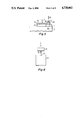
- FIG. 5 is a sketch of a mechanical linkage for the pivot motor according to one embodiment of the present invention.
- FIG. 6 illustrates the system used in a spinner type satellite configuration.
- FIG. 1 illustrates spacecraft 10 having principal axes X, Y and Z. These mutually perpendicular spacecraft axes extend from the center of mass at 10a.
- Axis Z is defined to be the spacecraft axis that is colinear with the total angular momentum vector H when the spacecraft is operating in its intended mission.
- the X, Y, and Z axes form an orthogonal right-handed coordinate system that is fixed in the body of the spacecraft.
- a momentum wheel or rotor 13 is initially aligned so that its angular momentum vector is approximately parallel to the Z axis.
- a motor 15 couples the relatively non-spinning platform or body 11, which may contain an antenna, and the spinning momentum wheel 13.
- the motor 15 speed is controlled so that the momentum of the wheel 13 is sufficient to provide gyroscopic stiffness to the satellite 10.
- the motor speed is also controlled to maintain the body or platform 11 with the antenna on one face pointing to earth. As such, in a geosynchronous orbit, the platform rotates once per day.
- This control is provided by a pitch loop control system as described, for example, by Kevin Phillips U.S. Pat. Nos. 3,695,554 and 3,830,447 incorporated herein by reference.
- the momentum wheel which is initially aligned with its angular momentum vector approximately parallel to the Z axis, is pivoted with a hinge mechanism parallel to the Y axis to allow the wheel's angular momentum vector to be moved within the plane defined by the X and Z axes.
- the wheel 13 is mounted on rotor shaft 17 to motor 15 and via another shaft 19 from motor 15 to a hinge 21.
- Hinge 21 lies on the Y' axis, which is parallel to the Y axis.
- a gyro sensor 23 is aligned with its sense axis parallel to the Y axis. This sensor 23 senses the angular rate of the platform about the Y axis until its magnitude exceeds the damper threshold as detected by threshold detector 25.
- the output signal from the threshold detector is processed by microprocessor 26 which controls a stepper motor 27.
- the stepper motor 27 is coupled by mechanical linkage (represented by dashed lines 29) to shaft 19 to move the shaft about hinge 21 on the Y' axis.
- the stepper motor 27 coupled between the body 11 and the arm 19 rotates the axis of the momentum wheel 13 relative to the Z axis of the platform 11 in steps about the Y' axis. If the direction of the nutation is in the same direction represented by arrow 13a of the wheel, then, if the zero crossing is from negative to positive, the motor pivots the wheel in N steps in the Y' direction. If, however, the sign changes from positive to negative, then the wheel is pivoted in N steps about the -Y' direction. One-half nutation period after the first of the N steps, the wheel is pivoted N steps in the opposite direction. The wheel is thus returned to its original position. This back and forth pivoting is repeated until the nutation is reduced to an acceptable level.
- the nutation is retrograde, namely: the direction of the wheel's spin is opposite that of the direction of nutation, damping is achieved by reversing the directions of the pivot motions. That is, if the zero crossing is from negative to positive, then the wheel pivots N steps about the -Y' direction, and, if the sign changes from positive to negative, then the wheel pivots N steps about the +Y' direction. Similarly, one-half nutation period after the first of the N steps, the wheel is pivoted N steps in the opposite direction.
- FIG. 2 illustrates the dynamics of the system.
- This diagram shows the trajectory of the spacecraft's total angular momentum vector projected on the platform-fixed XY plane.
- the wheel is normally aligned with the +Z axis.
- the normal trajectory, with no nutation, is simply the equilibrium point 31.
- the projection of the momentum vector follows a circular path, A, centered on point 31.
- the motion is counterclockwise as shown in FIG. 1.
- the Y axis sensor rate crosses from negative to positive at point 33, the system pivots the wheel about the +Y axis. Moving the momentum wheel causes the equilibrium point to move from point 31 to point 35 and the total angular momentum vector now follows the circular path B centered on point 35. This occurs due to the principle of conservation of angular momentum.
- nutation damping is achieved by moving the pivot back and forth through a fixed number of steps (N).
- N a fixed number of steps
- Using a large value for N produces rapid nutation damping, but the nutation angle cannot be reduced to as small a value as can be achieved if N is small.
- a small value of N enables damping to very small nutation angles, the damping rate is much slower.
- An alternative to using a fixed value for N is to use logic that selects N to be proportional to the nutation angle; namely, proportional to the peak Y axis angular rate. This approach rapidly damps large nutation angles and also reduces nutation to a very small angle.
- FIG. 3 illustrates for one implementation of the invention a flow chart of the operation of the microprocessor 26 of FIG. 1.
- the first decision represented by block 41, is if the damper is enabled. If it is disabled, that ends the program. If it is enabled, it then looks to see if the magnitude of the Y axis rate, ⁇ y , sensed by the gyro exceeds the threshold, ⁇ . This is represented by decision block 43. If it is below the threshold, then the logic restarts and the stepper motor 27 remains off. If ⁇ y exceeds the threshold, as represented by "yes”, then the value of K is determined according to -N sign ( ⁇ y ).
- the stepper motor pivots the wheel +K steps from the Z axis.
- T seconds equal to half the nutation period
- FIG. 4 illustrates an alternative flow chart for the microprocessor 26 of FIG. 1 according to a preferred embodiment.
- This flow chart is for an implementation in which the number of pivot steps is selected to be proportional to the nutation angle.
- the microprocessor determines whether the damper is enabled. If it is disable, processing ends. If it is enabled, the processor then determines whether the magnitude of the Y axis rate, ⁇ y , exceeds the threshold, ⁇ . This is represented by decision block 82. If ⁇ y is below the threshold, the logic restarts. Otherwise, as shown in dotted block 83, the microprocessor sets parameter S equal to -1 if ⁇ y is positive and equal to +1 if it is not. The microprocessor also sets parameter ⁇ 1 equal to zero.
- Dotted block 84 in FIG. 4 contains logic that determines the maximum magnitude of ⁇ y .
- the logic in block 84 is executed repeatedly until ⁇ y changes sign. Once that happens, K is set equal to the integer nearest ⁇ max (the maximum magnitude of ⁇ y ) multiplied by a proportionality constant or gain, C, and the sign parameter S.
- the stepper motor then pivots the wheel +K steps, and after a delay of T seconds (equal to half the nutation period), pivots the wheel -K steps to return it to its original alignment with the Z axis.
- T seconds equal to half the nutation period
- the implementations described above use a rate gyro mounted with its sense axis parallel to the spacecraft's Y axis. This, however, is not a requirement. Any other sensor that provides the proper timing information may be used. For example, an earth sensor, a sun sensor, an accelerometer, etc. may be used. Furthermore, the signal from the sensor does not have to be in phase with the Y axis angular rate. As long as the phase angle is known, an appropriate delay can be inserted into the logic so that the wheel is pivoted at the appropriate point during the nutation cycle.
- the momentum wheel axis need not be aligned in its initial state with the Z axis. It may instead be parallel and offset, and it may have an angular offset.
- FIG. 5 illustrates an implementation of the mechanical drive represented by dashed lines 19.
- the momentum wheel 13 may be rotatably mounted in a frame member 50 which is hinged by hinge 51 to a post 59 extending from the top of panel 11a on the satellite platform 11.
- the hinge 51 extends parallel to the Y axis, and the spin axis of the momentum wheel 13 is parallel to the Z axis in its centered position.
- the stepper drive motor 27 pivots the frame 50 and wheel 13 vertically as indicated by arrows 52 to provide pivoting under the control of a stepper motor.
- the stepper motor drives a screw 55 that is fixed to the top panel 11a of the platform 11 at end 55a.
- the opposite end 55b is coupled to the motor.
- the screw mates with a threaded collar 56 that is fitted to the frame 50 at point 57 directly opposite the hinge 51.
- the collar moves up and down in the direction of arrows 52 and tilts the wheel 13 and frame 50 about hinge 51.
- a spinner has a large rotor 61 performing the same function as the momentum wheel with a motor 62 coupling the rotor 61 and the despun platform 63.
- Nutation damping can be provided by pivoting either the platform or the rotor off the nominal angular momentum axis or Z axis by tilting the platform about a hinge along the Y axis (in and out of the paper through point 65).
- a motor coupled between bodies 61 and 63 may be provided to tilt the axis of the rotor 61 relative to the Z axis or relative to platform 63 and back again in accordance with the principles taught in this application to provide nutation damping.
Abstract
Description
Claims (8)
Priority Applications (6)
| Application Number | Priority Date | Filing Date | Title |
|---|---|---|---|
| US06/797,127 US4728062A (en) | 1985-11-12 | 1985-11-12 | Pivot actuated nutation damping for a dual-spin spacecraft |
| CA000521915A CA1282393C (en) | 1985-11-12 | 1986-10-31 | Pivot actuated nutation damping system for a dual-spin spacecraft |
| JP61268465A JPH0653519B2 (en) | 1985-11-12 | 1986-11-11 | Dual spin satellite nutation suppression device |
| DE19863638462 DE3638462A1 (en) | 1985-11-12 | 1986-11-11 | NUTATION DAMPING DEVICE FOR DOUBLE SPIRAL SPACE VEHICLES |
| GB8626931A GB2182624B (en) | 1985-11-12 | 1986-11-11 | Pivot actuated nutation damping system for a dual-spin spacecraft |
| FR868615696A FR2589819B1 (en) | 1985-11-12 | 1986-11-12 | PIVOTING NUTATION DAMPING DEVICE FOR A DOUBLE ROTATING SPACE MACHINE |
Applications Claiming Priority (1)
| Application Number | Priority Date | Filing Date | Title |
|---|---|---|---|
| US06/797,127 US4728062A (en) | 1985-11-12 | 1985-11-12 | Pivot actuated nutation damping for a dual-spin spacecraft |
Publications (1)
| Publication Number | Publication Date |
|---|---|
| US4728062A true US4728062A (en) | 1988-03-01 |
Family
ID=25169983
Family Applications (1)
| Application Number | Title | Priority Date | Filing Date |
|---|---|---|---|
| US06/797,127 Expired - Lifetime US4728062A (en) | 1985-11-12 | 1985-11-12 | Pivot actuated nutation damping for a dual-spin spacecraft |
Country Status (6)
| Country | Link |
|---|---|
| US (1) | US4728062A (en) |
| JP (1) | JPH0653519B2 (en) |
| CA (1) | CA1282393C (en) |
| DE (1) | DE3638462A1 (en) |
| FR (1) | FR2589819B1 (en) |
| GB (1) | GB2182624B (en) |
Cited By (8)
| Publication number | Priority date | Publication date | Assignee | Title |
|---|---|---|---|---|
| DE3918832A1 (en) * | 1988-06-16 | 1989-12-21 | Gen Electric | AIRPORT CONTROL ARRANGEMENT |
| US4911385A (en) * | 1987-04-30 | 1990-03-27 | Agrawal Brij N | Attitude pointing error correction system and method for geosynchronous satellites |
| US5172876A (en) * | 1990-08-03 | 1992-12-22 | Space Systems/Loral, Inc. | Spin reorientation maneuver for spinning spacecraft |
| US5308025A (en) * | 1992-07-30 | 1994-05-03 | Hughes Aircraft Company | Spacecraft spin axis capture system and method |
| JP2914998B2 (en) | 1988-05-26 | 1999-07-05 | スペイス・システムズ・ローラル・インコーポレイテッド | Transition control system for spacecraft attitude controller |
| US6377352B1 (en) * | 1999-03-17 | 2002-04-23 | Honeywell International Inc. | Angular rate and reaction torque assembly |
| US6772978B2 (en) * | 2002-02-22 | 2004-08-10 | Honeywell International Inc. | Dynamic unbalance compensation system and method |
| US20100019092A1 (en) * | 2008-07-23 | 2010-01-28 | Liu Dan Y | Systems and method of controlling a spacecraft using attitude sensors |
Families Citing this family (6)
| Publication number | Priority date | Publication date | Assignee | Title |
|---|---|---|---|---|
| EP0496184A1 (en) * | 1991-01-25 | 1992-07-29 | CONTRAVES ITALIANA S.p.A. | Attitude control actuator, particularly for spacecrafts |
| US5261631A (en) * | 1991-06-24 | 1993-11-16 | Hughes Aircraft Company | Momentum wheel platform steering system and method |
| FR2714357B1 (en) * | 1993-12-27 | 1996-03-22 | Aerospatiale | Method for minimizing, damping or compensating for disturbances on a satellite stabilized by autorotation. |
| FR2746366B1 (en) * | 1996-03-22 | 1998-08-14 | Aerospatiale | METHOD AND DEVICE FOR THE FAST MANEUVERING OF A PAYLOAD ON BOARD ON A SPATIAL PLATFORM |
| GB9622150D0 (en) * | 1996-10-24 | 1996-12-18 | Emhart Glass Mach Invest | Baffle assembly |
| CN100346866C (en) * | 2005-08-16 | 2007-11-07 | 卢作基 | Self-adaption flow-field ammonia jetter |
Citations (13)
| Publication number | Priority date | Publication date | Assignee | Title |
|---|---|---|---|---|
| US3591108A (en) * | 1967-01-27 | 1971-07-06 | Rca Corp | Control system for spinning bodies |
| US3638883A (en) * | 1968-05-21 | 1972-02-01 | Dynasciences Corp | Cross-rate axis sensor |
| US3685770A (en) * | 1971-03-03 | 1972-08-22 | British Aircraft Corp Ltd | Dampers for spinning bodies |
| US3695554A (en) * | 1970-10-16 | 1972-10-03 | Rca Corp | Nutation damping in dual-spin spacecraft |
| US3830447A (en) * | 1972-09-28 | 1974-08-20 | Rca Corp | Active nutation damping in dual-spin spacecraft |
| US3937423A (en) * | 1974-01-25 | 1976-02-10 | Hughes Aircraft Company | Nutation and roll error angle correction means |
| US3984071A (en) * | 1974-08-29 | 1976-10-05 | Trw Inc. | Satellite nutation attenuation apparatus |
| US4096427A (en) * | 1975-10-21 | 1978-06-20 | Hughes Aircraft Company | Nutation damping in dual-spin stabilized devices |
| US4193570A (en) * | 1978-04-19 | 1980-03-18 | The United States Of America As Represented By The Administrator Of The National Aeronautics And Space Administration | Active nutation controller |
| US4272045A (en) * | 1979-03-29 | 1981-06-09 | Rca Corporation | Nutation damping in a dual-spin spacecraft |
| US4370716A (en) * | 1979-01-23 | 1983-01-25 | Matra | Active nutation control system for space vehicle |
| US4386750A (en) * | 1980-08-29 | 1983-06-07 | The United States Of America As Represented By The Administrator Of The National Aeronautics And Space Administration | Method of damping nutation motion with minimum spin axis attitude disturbance |
| US4504032A (en) * | 1982-03-10 | 1985-03-12 | Rca Corporation | Control of nutation in a spacecraft |
Family Cites Families (2)
| Publication number | Priority date | Publication date | Assignee | Title |
|---|---|---|---|---|
| US3637170A (en) * | 1969-12-31 | 1972-01-25 | Thomas O Paine | Spacecraft attitude control method and apparatus |
| NL7102909A (en) * | 1970-03-05 | 1971-09-07 |
-
1985
- 1985-11-12 US US06/797,127 patent/US4728062A/en not_active Expired - Lifetime
-
1986
- 1986-10-31 CA CA000521915A patent/CA1282393C/en not_active Expired - Lifetime
- 1986-11-11 DE DE19863638462 patent/DE3638462A1/en active Granted
- 1986-11-11 GB GB8626931A patent/GB2182624B/en not_active Expired
- 1986-11-11 JP JP61268465A patent/JPH0653519B2/en not_active Expired - Lifetime
- 1986-11-12 FR FR868615696A patent/FR2589819B1/en not_active Expired - Fee Related
Patent Citations (13)
| Publication number | Priority date | Publication date | Assignee | Title |
|---|---|---|---|---|
| US3591108A (en) * | 1967-01-27 | 1971-07-06 | Rca Corp | Control system for spinning bodies |
| US3638883A (en) * | 1968-05-21 | 1972-02-01 | Dynasciences Corp | Cross-rate axis sensor |
| US3695554A (en) * | 1970-10-16 | 1972-10-03 | Rca Corp | Nutation damping in dual-spin spacecraft |
| US3685770A (en) * | 1971-03-03 | 1972-08-22 | British Aircraft Corp Ltd | Dampers for spinning bodies |
| US3830447A (en) * | 1972-09-28 | 1974-08-20 | Rca Corp | Active nutation damping in dual-spin spacecraft |
| US3937423A (en) * | 1974-01-25 | 1976-02-10 | Hughes Aircraft Company | Nutation and roll error angle correction means |
| US3984071A (en) * | 1974-08-29 | 1976-10-05 | Trw Inc. | Satellite nutation attenuation apparatus |
| US4096427A (en) * | 1975-10-21 | 1978-06-20 | Hughes Aircraft Company | Nutation damping in dual-spin stabilized devices |
| US4193570A (en) * | 1978-04-19 | 1980-03-18 | The United States Of America As Represented By The Administrator Of The National Aeronautics And Space Administration | Active nutation controller |
| US4370716A (en) * | 1979-01-23 | 1983-01-25 | Matra | Active nutation control system for space vehicle |
| US4272045A (en) * | 1979-03-29 | 1981-06-09 | Rca Corporation | Nutation damping in a dual-spin spacecraft |
| US4386750A (en) * | 1980-08-29 | 1983-06-07 | The United States Of America As Represented By The Administrator Of The National Aeronautics And Space Administration | Method of damping nutation motion with minimum spin axis attitude disturbance |
| US4504032A (en) * | 1982-03-10 | 1985-03-12 | Rca Corporation | Control of nutation in a spacecraft |
Non-Patent Citations (4)
| Title |
|---|
| "Satellite Attitude Control with a Gimbaled Reaction Wheel Digital Control System" by C. H. Much et al., Automatica, vol. 8, pp. 9-21, Pergamon Press, 1972. |
| AIAA Paper No. 70 456 of the 3rd Communications Satellite Systems Conference of Apr. 6 8, 1970; Three Axis Attitude Control of a Synchronous Communications Satellite by J. U. Beusch et al. * |
| AIAA Paper No. 70-456 of the 3rd Communications Satellite Systems Conference of Apr. 6-8, 1970; "Three Axis Attitude Control of a Synchronous Communications Satellite" by J. U. Beusch et al. |
| Satellite Attitude Control with a Gimbaled Reaction Wheel Digital Control System by C. H. Much et al., Automatica, vol. 8, pp. 9 21, Pergamon Press, 1972. * |
Cited By (10)
| Publication number | Priority date | Publication date | Assignee | Title |
|---|---|---|---|---|
| US4911385A (en) * | 1987-04-30 | 1990-03-27 | Agrawal Brij N | Attitude pointing error correction system and method for geosynchronous satellites |
| JP2914998B2 (en) | 1988-05-26 | 1999-07-05 | スペイス・システムズ・ローラル・インコーポレイテッド | Transition control system for spacecraft attitude controller |
| DE3918832A1 (en) * | 1988-06-16 | 1989-12-21 | Gen Electric | AIRPORT CONTROL ARRANGEMENT |
| US4916622A (en) * | 1988-06-16 | 1990-04-10 | General Electric Company | Attitude control system |
| US5172876A (en) * | 1990-08-03 | 1992-12-22 | Space Systems/Loral, Inc. | Spin reorientation maneuver for spinning spacecraft |
| US5308025A (en) * | 1992-07-30 | 1994-05-03 | Hughes Aircraft Company | Spacecraft spin axis capture system and method |
| US6377352B1 (en) * | 1999-03-17 | 2002-04-23 | Honeywell International Inc. | Angular rate and reaction torque assembly |
| US6772978B2 (en) * | 2002-02-22 | 2004-08-10 | Honeywell International Inc. | Dynamic unbalance compensation system and method |
| US20100019092A1 (en) * | 2008-07-23 | 2010-01-28 | Liu Dan Y | Systems and method of controlling a spacecraft using attitude sensors |
| US8620496B2 (en) | 2008-07-23 | 2013-12-31 | The Boeing Company | Systems and method of controlling a spacecraft using attitude sensors |
Also Published As
| Publication number | Publication date |
|---|---|
| DE3638462A1 (en) | 1987-05-21 |
| GB2182624B (en) | 1989-10-04 |
| DE3638462C2 (en) | 1990-02-22 |
| JPS63130499A (en) | 1988-06-02 |
| FR2589819B1 (en) | 1992-03-06 |
| FR2589819A1 (en) | 1987-05-15 |
| GB8626931D0 (en) | 1986-12-10 |
| JPH0653519B2 (en) | 1994-07-20 |
| CA1282393C (en) | 1991-04-02 |
| GB2182624A (en) | 1987-05-20 |
Similar Documents
| Publication | Publication Date | Title |
|---|---|---|
| US4230294A (en) | Closed loop roll control for momentum biased satellites | |
| US4728062A (en) | Pivot actuated nutation damping for a dual-spin spacecraft | |
| US6039290A (en) | Robust singularity avoidance in satellite attitude control | |
| US4071211A (en) | Momentum biased active three-axis satellite attitude control system | |
| US5020745A (en) | Reaction wheel fricton compensation using dither | |
| US6305647B1 (en) | Method and apparatus for steering the attitude of a satellite | |
| US7661627B2 (en) | Method of controlling the attitude of satellites, particularly agile satellites with a reduced number of gyrodynes | |
| US5441222A (en) | Attitude control of spinning spacecraft | |
| JP4550347B2 (en) | System and method for controlling the attitude of a spacecraft | |
| EP0739818B1 (en) | Satellite spin axis stabilization using a single degree of freedom transverse momentum storage device | |
| US4916622A (en) | Attitude control system | |
| US3830447A (en) | Active nutation damping in dual-spin spacecraft | |
| US6311931B1 (en) | Bi-directional momentum bias spacecraft attitude control | |
| US3567155A (en) | Gravity gradient attitude control system | |
| US4424948A (en) | Magnetically torqued nutation damping | |
| US4504032A (en) | Control of nutation in a spacecraft | |
| US6789437B2 (en) | Apparatus for precision slewing of flatform-mounted devices | |
| US3471105A (en) | Stabilization control system | |
| US4272045A (en) | Nutation damping in a dual-spin spacecraft | |
| EP0372397A2 (en) | Spin stabilization method using momentum wheels | |
| US3476129A (en) | Stabilization-orientation system | |
| US6196502B1 (en) | Attitude control of spinning spacecraft with counterspun controls platform | |
| EP0321513B1 (en) | Nutation sensor and nutation control system for a dual-spin stabilized satellite | |
| EP0496184A1 (en) | Attitude control actuator, particularly for spacecrafts | |
| US6152402A (en) | Dual spin zero momentum satellite system |
Legal Events
| Date | Code | Title | Description |
|---|---|---|---|
| AS | Assignment |
Owner name: RCA CORPORATION, A CORP OF DELAWARE Free format text: ASSIGNMENT OF ASSIGNORS INTEREST.;ASSIGNOR:HUBERT, CARL H.;REEL/FRAME:004482/0938 Effective date: 19851108 |
|
| STCF | Information on status: patent grant |
Free format text: PATENTED CASE |
|
| AS | Assignment |
Owner name: GENERAL ELECTRIC COMPANY Free format text: MERGER;ASSIGNOR:R C A CORPORATION, A CORP. OF DE.;REEL/FRAME:004837/0618 Effective date: 19880129 Owner name: GENERAL ELECTRIC COMPANY,STATELESS Free format text: MERGER;ASSIGNOR:R C A CORPORATION, A CORP. OF DE.;REEL/FRAME:004837/0618 Effective date: 19880129 |
|
| CC | Certificate of correction | ||
| FEPP | Fee payment procedure |
Free format text: PAYOR NUMBER ASSIGNED (ORIGINAL EVENT CODE: ASPN); ENTITY STATUS OF PATENT OWNER: LARGE ENTITY |
|
| FPAY | Fee payment |
Year of fee payment: 4 |
|
| AS | Assignment |
Owner name: MARTIN MARIETTA CORPORATION, MARYLAND Free format text: ASSIGNMENT OF ASSIGNORS INTEREST;ASSIGNOR:GENERAL ELECTRIC COMPANY;REEL/FRAME:007046/0736 Effective date: 19940322 |
|
| FPAY | Fee payment |
Year of fee payment: 8 |
|
| AS | Assignment |
Owner name: LOCKHEED MARTIN CORPORATION, MARYLAND Free format text: ASSIGNMENT OF ASSIGNORS INTEREST;ASSIGNOR:MARTIN MARIETTA CORPORATION;REEL/FRAME:008628/0518 Effective date: 19960128 |
|
| FEPP | Fee payment procedure |
Free format text: PAYOR NUMBER ASSIGNED (ORIGINAL EVENT CODE: ASPN); ENTITY STATUS OF PATENT OWNER: LARGE ENTITY |
|
| FEPP | Fee payment procedure |
Free format text: PAYER NUMBER DE-ASSIGNED (ORIGINAL EVENT CODE: RMPN); ENTITY STATUS OF PATENT OWNER: LARGE ENTITY |
|
| FPAY | Fee payment |
Year of fee payment: 12 |