JP4550347B2 - System and method for controlling the attitude of a spacecraft - Google Patents
System and method for controlling the attitude of a spacecraft Download PDFInfo
- Publication number
- JP4550347B2 JP4550347B2 JP2001556743A JP2001556743A JP4550347B2 JP 4550347 B2 JP4550347 B2 JP 4550347B2 JP 2001556743 A JP2001556743 A JP 2001556743A JP 2001556743 A JP2001556743 A JP 2001556743A JP 4550347 B2 JP4550347 B2 JP 4550347B2
- Authority
- JP
- Japan
- Prior art keywords
- axis
- attitude control
- spacecraft
- control system
- wheel
- Prior art date
- Legal status (The legal status is an assumption and is not a legal conclusion. Google has not performed a legal analysis and makes no representation as to the accuracy of the status listed.)
- Expired - Lifetime
Links
- 238000000034 method Methods 0.000 title description 7
- 238000006243 chemical reaction Methods 0.000 claims description 68
- 238000004891 communication Methods 0.000 claims description 8
- 230000004044 response Effects 0.000 claims description 4
- 230000008878 coupling Effects 0.000 claims description 2
- 238000010168 coupling process Methods 0.000 claims description 2
- 238000005859 coupling reaction Methods 0.000 claims description 2
- 230000007246 mechanism Effects 0.000 description 8
- 239000000725 suspension Substances 0.000 description 8
- 238000010586 diagram Methods 0.000 description 7
- 238000000926 separation method Methods 0.000 description 4
- 239000000446 fuel Substances 0.000 description 3
- 238000012986 modification Methods 0.000 description 3
- 230000004048 modification Effects 0.000 description 3
- 230000001133 acceleration Effects 0.000 description 2
- 238000013461 design Methods 0.000 description 2
- 238000001514 detection method Methods 0.000 description 2
- 230000006870 function Effects 0.000 description 2
- 239000011159 matrix material Substances 0.000 description 2
- 238000009987 spinning Methods 0.000 description 2
- 230000006641 stabilisation Effects 0.000 description 2
- 238000011105 stabilization Methods 0.000 description 2
- 230000006978 adaptation Effects 0.000 description 1
- 230000009286 beneficial effect Effects 0.000 description 1
- 230000008859 change Effects 0.000 description 1
- 230000000694 effects Effects 0.000 description 1
- 230000008030 elimination Effects 0.000 description 1
- 238000003379 elimination reaction Methods 0.000 description 1
- 230000007274 generation of a signal involved in cell-cell signaling Effects 0.000 description 1
- 230000005484 gravity Effects 0.000 description 1
- 238000005259 measurement Methods 0.000 description 1
- 238000005192 partition Methods 0.000 description 1
- 230000005855 radiation Effects 0.000 description 1
- 238000013519 translation Methods 0.000 description 1
Images


Classifications
-
- B—PERFORMING OPERATIONS; TRANSPORTING
- B64—AIRCRAFT; AVIATION; COSMONAUTICS
- B64G—COSMONAUTICS; VEHICLES OR EQUIPMENT THEREFOR
- B64G1/00—Cosmonautic vehicles
- B64G1/22—Parts of, or equipment specially adapted for fitting in or to, cosmonautic vehicles
- B64G1/24—Guiding or controlling apparatus, e.g. for attitude control
- B64G1/36—Guiding or controlling apparatus, e.g. for attitude control using sensors, e.g. sun-sensors, horizon sensors
-
- B—PERFORMING OPERATIONS; TRANSPORTING
- B64—AIRCRAFT; AVIATION; COSMONAUTICS
- B64G—COSMONAUTICS; VEHICLES OR EQUIPMENT THEREFOR
- B64G1/00—Cosmonautic vehicles
- B64G1/22—Parts of, or equipment specially adapted for fitting in or to, cosmonautic vehicles
- B64G1/24—Guiding or controlling apparatus, e.g. for attitude control
- B64G1/28—Guiding or controlling apparatus, e.g. for attitude control using inertia or gyro effect
- B64G1/281—Spin-stabilised spacecraft
-
- B—PERFORMING OPERATIONS; TRANSPORTING
- B64—AIRCRAFT; AVIATION; COSMONAUTICS
- B64G—COSMONAUTICS; VEHICLES OR EQUIPMENT THEREFOR
- B64G1/00—Cosmonautic vehicles
- B64G1/22—Parts of, or equipment specially adapted for fitting in or to, cosmonautic vehicles
- B64G1/24—Guiding or controlling apparatus, e.g. for attitude control
- B64G1/28—Guiding or controlling apparatus, e.g. for attitude control using inertia or gyro effect
- B64G1/283—Guiding or controlling apparatus, e.g. for attitude control using inertia or gyro effect using reaction wheels
-
- B—PERFORMING OPERATIONS; TRANSPORTING
- B64—AIRCRAFT; AVIATION; COSMONAUTICS
- B64G—COSMONAUTICS; VEHICLES OR EQUIPMENT THEREFOR
- B64G1/00—Cosmonautic vehicles
- B64G1/22—Parts of, or equipment specially adapted for fitting in or to, cosmonautic vehicles
- B64G1/24—Guiding or controlling apparatus, e.g. for attitude control
- B64G1/28—Guiding or controlling apparatus, e.g. for attitude control using inertia or gyro effect
- B64G1/285—Guiding or controlling apparatus, e.g. for attitude control using inertia or gyro effect using momentum wheels
-
- B—PERFORMING OPERATIONS; TRANSPORTING
- B64—AIRCRAFT; AVIATION; COSMONAUTICS
- B64G—COSMONAUTICS; VEHICLES OR EQUIPMENT THEREFOR
- B64G1/00—Cosmonautic vehicles
- B64G1/22—Parts of, or equipment specially adapted for fitting in or to, cosmonautic vehicles
- B64G1/24—Guiding or controlling apparatus, e.g. for attitude control
- B64G1/36—Guiding or controlling apparatus, e.g. for attitude control using sensors, e.g. sun-sensors, horizon sensors
- B64G1/369—Guiding or controlling apparatus, e.g. for attitude control using sensors, e.g. sun-sensors, horizon sensors using gyroscopes as attitude sensors
Description
【0001】
【発明の属する技術分野】
本発明は一般に宇宙船の姿勢を制御するシステムに関する。とくに、本発明は回転(スピン)している衛星の姿勢を制御するシステムに関する。
【0002】
【従来の技術】
衛星は通信システムおよび全地球測位システムから宇宙望遠鏡システムまでを範囲とする種々の要求のきびしい適用において使用されている。このような適用では、正確な操縦、ステーションキーピングおよび姿勢調節能力を備えた衛星がしばしば必要とされる。
【0003】
衛星の姿勢を正確に調節するシステムはとくに、通信および宇宙望遠鏡に適用する場合において重要である。たとえば、通信衛星に指向された地上ベースの受信機またはトランシーバがその衛星と通信するには、その衛星が現在の位置およびオリエンテーションを維持したままであることがしばしば必要とされる。同様に、特定の宇宙領域に焦点を結ぶ宇宙望遠鏡衛星は正確に方向付けられることが多い。
【0004】
姿勢制御機構および宇宙船操縦システムがない場合には、衛星はランダムな軸を中心として回転する。この回転は、衛星の発射中に生じたモーメント、太陽放射圧力および、または重力勾配から結果的に発生する可能性がある。
【0005】
宇宙船の姿勢を制御するために、スラスタがしばしば使用される。スラスタは衛星のオリエンテーションに対する粗制御を行うが、一般に多くの衛星適用によって要求される姿勢の微調節を行う能力を欠いている。スラスタはまた過度に燃料を消費し、そのために宇宙船の重量および費用が増加し、宇宙船の有効寿命期間を制限する。
【0006】
スラスタは一般に、回転している通信衛星のような初期運動量がゼロでないものを含む大部分の宇宙船上で使用されている。スラスタが回転している宇宙船上で使用された場合、それらは大きいトルクを供給して宇宙船運動量ベクトルを所望の位置に移動させなければならない。(これは、自転車のホイール効果として知られている)。必要なトルクは結果的に燃料消費量を増加させる。
【0007】
宇宙船オリエンテーションをもっと微細に制御し、高価なスラスタの必要性を減少させるために、ジンバルで支持された運動量ホイールを使用するシステムがしばしば使用される。このシステムは、その内容がここにおいて参考文献とされているH.Rosen氏による米国特許第 5,441,222号明細書(ATTITUDE CONTROL OF A SPINNING SPACECRAFT )に開示されている。そのシステムには、2軸ジンバルで支持された運動量ホイールが含まれている。このホイールが回転されて存在している宇宙船運動量を消去し、その結果宇宙船の運動量がゼロになる。その後、ゼロ運動量の宇宙船は、ホイール構造体を押して所望の方向に反動力を生じさせるアクチュエータによって生成された慣性モーメントによって方向付けられる。
【0008】
【発明が解決しようとする課題】
しかしながら、ジンバルで支持された運動量ホイールの使用にはいくつかの欠点を有している。一般に、宇宙船の設計制約のために運動量ホイールの寸法および質量が制限される。その結果、運動量ホイールはその宇宙船の全運動量を消去するために高速で回転しなければならない。運動量ホイールはしばしば5000回転/分より速い速度で回転しなければならない。この結果、除去し難い望ましくない高周波宇宙船振動が生じる可能性が高い。望ましくない高周波外乱を減少させるために、しばしば高価で複雑な運動量ホイール分離システムおよび、または制御ループが必要とされる。
【0009】
したがって、宇宙船を正確に方向付ける経済的なシステムが技術的に必要とされている。さらに、高周波宇宙船振動を導入せず、あるいは過度の燃料を消費しないシステムが必要とされている。
【0010】
【課題を解決するための手段】
この技術的な要求は、本発明の宇宙船用姿勢制御システムにより満たされる。示されている実施形態において、本発明のシステムは、姿勢制御素子が取付けられたペイロードを有する衛星により使用されるように構成されている。バスは、これがペイロードに関して1自由度の継手を中心として回転するように、この継手によってペイロードに接続されている。したがって、バスに関してペイロードを回転させるためのアクチュエータおよび制御回路が内蔵されている。
【0011】
特定の実施形態では、バスは1自由度の回転継手(しばしばBapta継手と呼ばれる)によりペイロードに接続されている。バスは第1の軸を中心とするペイロードの運動量を消去するように駆動される。これによってゼロ純運動量の宇宙船が提供される。宇宙船の内部発生力または運動量を与えることにより宇宙船を方向付けて、その宇宙船を第1の軸に垂直な2つの軸で制御する付加的な制御装置が内蔵されている。
【0012】
特定の実施形態において、衛星はバスセクションおよびペイロードセクションを備えている。宇宙船のバスは記憶セクションとして機能し、姿勢制御素子を収容することができる。バスはペイロードの慣性モーメントと同程度の慣性モーメントを持つ質量を有するであろうことが予測される。第1の制御回路はBapta継手を介してペイロードに関するバスのオリエンテーションを制御する。第1の制御回路は、Bapta継手アクチュエータを駆動し、それによってペイロードを回転させるアクチュエータ制御信号を計算するスピン制御装置である。第1の制御回路はさらに、3つの各軸を中心とした、バスに関するペイロードの角速度を決定するために速度検出器を備えている。この特定の実施形態では、速度検出器は、スピン制御装置と通信しているジャイロスコープセンサパッケージおよびタコメータを含んでいる。ジャイロスコープセンサパッケージは、宇宙船の運動量を表す速度信号をコンピュータに供給する。そのコンピュータは、ジャイロスコープおよびタコメータセンサパッケージからの速度信号の受信に応答して、スピン制御信号を発生するソフトウェアを実行する。
【0013】
回転軸制御回路に加えて、回転軸に垂直な2つの姿勢角度を制御するために2つの付加的な制御回路が使用される。必要とされる制御回路は特定用途向け型であり、所定の用途のニーズを満たすように当業者により決定されてもよい。
【0014】
1実施形態において、付加的な制御装置は、第1のホイールが取付けられているジンバルの回転軸に垂直な回転軸を有する第1の反動ホイールを制御する。このジンバルは、Bapta機構の回転軸にほぼ平行な回転軸を有している。制御回路は、ジンバルおよび反動ホイール上に取付けられたセンサからの角度的位置および速度の測定値、ならびにジャイロスコープセンサパッケージからの角速度信号を使用して、ジンバルおよび反動ホイール上に取付けられたトルクモータにコンピュータを介してトルク信号を発生する。
【0015】
第2の実施形態において、付加的な制御装置は第1の反動ホイールおよび第2の反動ホイールを備えている。第1および第2の反動ホイールは宇宙船バスにしっかりと取付けられており、それぞれ第1および第2の互いに垂直な軸を中心として自由に回転することができる。第1および第2の反動ホイールはそれぞれ第1および第2の操縦制御信号に応答して、第1および第2のアクチュエータにより選択的に回転される。その制御信号は制御装置によって発生される。この制御装置は、技術的によく知られているようにホイール上に取付けられたジャイロスコープセンサパッケージ、スタートラッカおよびタコメータと通信している。
【0016】
第3の実施形態において、付加的な制御装置は、可撓性サスペンションを介して宇宙船に取付けられた反動質量を含んでいる。第1の力アクチュエータは第1の力を反動質量に与えて宇宙船の方位制御を容易にする。第2の力アクチュエータは第2の力を反動質量に与えて宇宙船の方位調整を容易にする。第1および第2の力アクチュエータはそれぞれ、操縦制御信号の受信に応答して第1および第2の力を選択的に生成する音声コイルアクチュエータである。これらのアクチュエータは、宇宙船が回転軸に直交する2つの軸で操縦されることができるように配置される。近接センサは、宇宙船に関する反動質量の角度を測定する。その後、ジャイロスコープセンサパッケージ、スタートラッカおよび近接センサと通信しているコンピュータ上で実行するソフトウェアによって宇宙船操縦トルクコマンドが発生される。
【0017】
本発明の特有の設計は、宇宙船の運動量を消去するために逆回転バスおよび付随のBapta機構を使用することによって容易になる。バスの質量特性のために、一般に、バスの比較的遅い回転だけが宇宙船運動量を消去するために必要である。遅い回転の結果、宇宙船振動が最小になる。結果的に生じる振動は、一般に、技術的によく知られている制御装置によって容易に除去される低周波振動である。これによって、高価な運動量ホイール分離システムが必要でなくなり、その結果さらに経済的な宇宙船が可能になる。さらに、Bapta機構のバスは記憶区画として使用可能であり、したがって宇宙船の空間および重量が効率的に使用される。
【0018】
【発明の実施の形態】
本発明はここでは特定の適用に対する例示的な実施形態を参照して説明されているが、本発明はそれに限定されないことを理解すべきである。当業者は、本発明の技術的範囲内における付加的な修正、適応および実施形態、ならびに本発明が非常に有益な付加的な分野を認識するであろう。
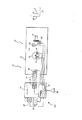
図1は、本発明の第1の実施形態に対応した衛星10の概略図である。衛星10は姿勢制御セクション12に結合されたペイロード14を備えている。姿勢制御セクション12はバス16を備えており、このバス16は一方の端部がBapta継手18によってペイロード14に結合されてい。Bapta継手18、バス16およびペイロード14はz軸24と同軸に配置されている。第1の反動ホイール20および第2の反動ホイール22はバス16の反対側の端部においてそれぞれx軸26およびy軸28と同軸方向に取付けられている。
【0019】
Bapta継手18は1自由度を有し、姿勢制御セクション12がz軸24だけを中心として回転することを可能にする。同様に、第1の反動ホイール20はx軸26を中心とした回転だけが可能であり、第2の反動ホイール22はy軸28を中心とした回転だけが可能である。姿勢制御セクション12がz軸24を中心として回転したとき、x軸26およびy軸28は共にz軸を中心として回転する。
【0020】
当業者は、本発明の技術的範囲を逸脱することなく反動ホイール20および22がx軸26およびy軸28に関して角度付けされた軸のような異なった軸を中心として回転するホイールにより置換されてもよいことを認識するであろう。しかしながら、ホイールは、それらがz軸24、すなわち、衛星10の回転軸に直交する2つの異なった方向に2つの異なったトルク成分を提供することができるように位置されなければならない。
【0021】
姿勢制御セクション12は、Bapta継手18ならびに反動ホイール20および22に結合されたアクチュエータを備えており、これらアクチュエータは、以下さらに詳細に説明するように宇宙船コンピュータからのコマンドによって選択的に制御される。姿勢制御セクション12はBapta継手18を中心として選択的に回転され、存在する宇宙船運動量を消去する。宇宙船10の全運動量がゼロに減少された後、反動ホイール20および22が回転されてx軸26および、またはy軸28に沿ったトルクを生成し、衛星10を所望のオリエンテーションに移動させる。
【0022】
姿勢制御セクション12は、衛星10の全運動量を消去するためにペイロード14に関してBapta継手18を中心としてを逆回転するように命令される(以下さらに詳細に説明するように)。
【0023】
図2は、図1の衛星10内に構成されている姿勢制御システム30を示すブロック図である。姿勢制御システム30は、ペイロード14内に位置された宇宙船コンピュータ32を備えている。宇宙船コンピュータ32はジャイロスコープセンサパッケージ34およびスタートラッカ36に結合されており、それら両者はバス16とは反対側のペイロード14の外側に取付けられている。宇宙船コンピュータ32はまたBapta位置センサ38、Baptaアクチュエータ40、第1のホイールタコメータ42、第1のホイールアクチュエータ44、第2のホイールタコメータ46および第2のホイールアクチュエータ48に結合されている。
【0024】
動作において、宇宙船コンピュータ32は、以下さらに詳細に説明するように、ジャイロスコープセンサパッケージ34、スタートラッカ36、Bapta位置センサ38ならびにホイールタコメータ42および46からの入力に応答してBaptaアクチュエータ40ならびにホイールアクチュエータ20および22を制御する姿勢制御プログラム(ソフトウェアで実施されることが好ましい)によって制御計算を行う。
【0025】
ジャイロスコープセンサパッケージ34内のジャイロスコープセンサはペイロード14の角回転速度を感知し、宇宙船コンピュータ32への主フィードバックを行う。宇宙船コンピュータ32上で実行している姿勢制御プログラムは、Baptaアクチュエータ40によりバス16を含む姿勢制御セクション12を回転させ、ジャイロセンサパッケージ34により検出された存在している宇宙船運動量を消去するように設計されている。姿勢制御プログラムはまた、衛星10の姿勢を調節するためのモーメントを生成するために反動ホイール20および22を選択的に回転させる命令を含んでいる。スタートラッカ36は宇宙船コンピュータ32にフィードバックを行って、衛星10の現在のオリエンテーションを示す。
【0026】
姿勢制御プログラムは、宇宙船コンピュータ32上のメモリに記憶された姿勢情報により特定された所望の宇宙船オリエンテーションをスタートラッカ36およびジャイロスコープセンサパッケージ34により提供された姿勢情報と比較し、宇宙船コンピュータ32によりホイールアクチュエータ42および48に入力される操縦制御信号を発生する。ペイロード14上に取付けられ、宇宙船コンピュータ32に接続された受信機50は、所望のオリエンテーションに向くように宇宙船に命令するテレメトリ制御信号を受信するために設けられている。
【0027】
当業者は、本発明の技術技術的範囲を逸脱することなく宇宙船コンピュータ32および受信機50のような姿勢制御システム30のコンポーネントが図2に示されている位置とは別の位置に配置されてもよいことを認識するであろう。たとえば、宇宙船コンピュータ32および受信機50はバス16上に配置されてもよい。
【0028】
衛星10がスタートラッカ36およびジャイロスコープセンサパッケージ34からの入力により指示された所望のオリエンテーションに向いた後、衛星がその所望のオリエンテーションに向いたまま保持されるように、ホイール20および、または22の回転速度が落とされる。第1のホイールタコメータ44および第2のホイールタコメータ46はそれぞれ第1の反動ホイール20および第2の反動ホイール22の回転速度に関する情報を宇宙船コンピュータ32に供給する。姿勢制御プログラムはそのホイール回転速度情報を使用して、ホイールの存在している回転速度を決定する。姿勢制御プログラムは存在している回転速度情報を使用して、第1のホイールアクチュエータ42および、または第2のホイールアクチュエータ48を制御して予め定められた量だけ回転速度を調節するためのアクチュエータ制御信号の発生を容易にする。同様に、Bapta位置または速度センサ38は、ペイロード14に関するバス16の回転速度についての情報を宇宙船コンピュータ32上で実行する姿勢制御プログラムに提供する。姿勢制御プログラムはこの加速情報を使用してBaptaアクチュエータ40を制御し、予め定められた量だけ回転速度を調節する。
【0029】
Bapta位置センサ38ならびに反動ホイールタコメータ44および46を使用することによって、宇宙船コンピュータ32上で実行する姿勢制御プログラムによる運動量の消去が容易になる。
【0030】
上記の手順を実施するソフトウェアは、当業者により図3を参照して容易に生成される。さらに、当業者は、本発明の技術的範囲を逸脱することなく反動ホイールタコメータ44および46ならびにBapta位置センサ38が別のセンサ素子により置換されてもよいことを認識するであろう。この場合、宇宙船コンピュータ32上で実行する制御プログラムは適切に変更される。
【0031】
多くの適用に対して、姿勢制御セクション12の慣性モーメントは、ペイロード14の慣性モーメントと同程度の大きさになるであろうと予測される。その結果、これらの適用では、存在している宇宙船運動量を消去するために姿勢制御セクション12が比較的遅く逆回転することが要求される。姿勢制御セクション12が逆回転した結果生じた宇宙船振動は、技術的によく知られている手順によって容易に除去される。これによって高価な運動量ホイール分離システムが必要なくなる。
【0032】
バス16は、通常衛星上に設けられている電子機器その他のデバイス(示されていない)を搭載されている。したがって、姿勢制御セクション12は、バス16内に記憶スペースが設けられ、衛星10の姿勢制御を容易にするように機能する。バス16を記憶区画として使用することによって、重量節約が達成される。
【0033】
従来技術の姿勢制御システムはしばしば、比較的小さいが質量の大きい運動量ホイールが必要である。運動量ホイールの高密度要求は典型的に補助記憶区画としてのホイールの使用から除外される。
【0034】
姿勢制御セクション12は、ペイロード14の運動量を正確に消去する速度で回転する低速逆回転機構として考えられてもよい。運動量を消去するために高速運動量ホイールではなく低速機構を使用することによって、高価な運動量ホイール分離システムが不要になる。当業者は、宇宙船の方位を制御するために、回転軸24に直交するトルクの2つの軸を提供する任意の内部機構が制御アクチュエータとして十分であることを認識するであろう。
【0035】
衛星10が有する純運動量はゼロなので、衛星10は内力およびモーメントを使用して任意の位置に方向付けられることができる。ビークルの安体化を行うためにスラスタまたは外部モーメントは必要ない。さらに、ビークルの安体化を容易にするために、本発明の技術的範囲を逸脱することなくダイナミックな平衡機構が構成されてもよい。
【0036】
示されている実施形態において、第1の反動ホイール20および第2の反動ホイール22は同じ質量および慣性モーメントを有している。ホイール20および22はそれぞれx軸26およびy軸28を中心として回転するが、他のいずれの軸を中心とした回転または変換を行うことはてきない。ホイール20および22は、DCトルクモータ(以下さらに詳細に説明する)として構成された標準的なアクチュエータを使用することによりそれらの各軸26および28を中心として回転する。反動ホイール20および22は、それらが公称的に固定した速度で回転しないため、運動量ホイールではない。ホイール20および22はゼロの公称速度を有している。
【0037】
以下の力学式は、第1の反動ホイール20および第2の反動ホイール22を有する図1の衛星10に関するものである。当業者は、以下の制御式が本発明の姿勢制御システムの構成方法だけを表すものではないことを認識するであろう。
【0038】
以下の力学制御式では、各質量体、すなわち、ペイロード14と、バス16と、第1の反動ホイール20と、および第2の反動ホイール22に対して、慣性テンソルが0の慣性乗積項を有していると仮定されている。一般に、以下の力学式が有効なままであるように、事実上慣性乗積項は十分に小さいままである。また、本体14、16、20および22間のアタッチメントは完全な摩擦のないアタッチメントであると仮定されている。たとえば、ペイロード14およびバス16は、ペイロード14およびバス16がz軸24を中心として回転するが、その他の軸を中心とした回転は行わないことを可能にする完全ピンであるBapta継手18により連結されている。
【0039】
各本体14、16、20および22に対して、最も外側の本体(ホイール20および22)から始まってペイロード14に向かってオイラーの運動方程式を適用することによって、当業者は特定の衛星軌道に関する運動方程式を導出し、それらを線形化することができる。
【0040】
特定の衛星軌道に関する運動方程式を線形化した結果、ペイロード14のオリエンテーションの完全な可制御性を可能にする方程式の線形系が得られる。運動量の保存は、衛星10の全ての位置状態が完全に制御可能であることを許さない(バスおよびホイールは同時に制御できない)。しかしながら、この実施形態では、ペイロード14のオリエンテーションを制御することだけしか必要はない。
【0041】
公称軌道において、ペイロードはz軸24を中心として所望の回転速度ωs で回転し、一方横軸の回転速度はゼロである。例示的な線形化軌道は以下のマトリックス式によって与えられる:
【数2】

【0042】
一般的にはバス16はペイロード14の回転速度と比較して任意の速度で回転するが、式(1)では、バス16はペイロード14と全く同じ速度で逆方向に回転していると仮定されている。バス16は衛星10の全慣性をゼロにするように回転する。
【0043】
式1の線形化軌道の結果、以下の線形化された式が得られる:
【数3】
【0044】
一般に、
【数4】
【0045】
当業者は、式(4)が式(1)の線形化された軌道に適度に近い任意の軌道で制御可能な式を表すことを容易に証明することができる。可制御性が証明された後、式(4)において特定された法則にしたがって衛星10のオリエンテーションを制御するための局部的に安定した制御装置を構成するために、通常の利得のスケジュール化された制御装置、LPV制御装置および、または非線形制御装置が使用されることができる。
【0046】
当業者は、以下の量:
【数5】
【0047】
この特定の実施形態では、
【数6】
【数7】
【数8】
【数9】
【数10】
【0048】
一般に、式(9)はゼロではない。したがって、姿勢制御セクション12は衛星10のシステム30によって完全に制御可能であり、システム30を制御するために、古典的なもの、極配置、Hインフィニティ等の任意の一般的な制御方法が使用できる。当業者は適切なゲインスケジューリングを実施して、制御装置をバスに対するペイロードの角度の関数として容易に変更することができる。
【0049】
IBx=IByおよびIPx=IPyである(すなわち、ペイロードおよびバスの両者が完全な円筒形に似ている)異常な場合には、5より低い可制御性マトリックスが発生し、ここで、
【数11】
【数12】
【数13】
【0050】
式(12)の制御法則はプラットフォーム速度を安定させ、制御不可能な状態(ホイール速度)を制限する。これは望ましい特性である。
【0051】
図3は、図2の宇宙船コンピュータ32により実行されるプログラム51の重要な機能ブロックを示す図である。プログラムは、位置検出ルーチン52、位置比較ルーチン54、エラー補償ルーチン56、およびアクチュエータ制御ルーチン58を含んでいる。
【0052】
図2および3を参照すると、位置検出ルーチン52は現在の宇宙船位置情報を求めてジャイロスコープセンサパッケージ34およびスタートラッカ36をサンプリングし、受信機50ようなテレメタリから位置コマンドを受信する。現在の宇宙船位置情報は、受信機50からの任意の命令された位置情報と共に比較ルーチン54に供給される。
比較ルーチン54は、受信機50から受信された信号によって示されるか、あるいはエラー補償ルーチン56の先行する出力から受信された信号によって示されるような命令された位置を、位置検出器ルーチンにより示される宇宙船10の現在の位置と比較する。比較ルーチン54は、命令された位置と現在の位置の違いを表すエラー信号を供給する。
【0053】
エラー補償ルーチン56は位置コマンドを供給し、エラー信号を最小にするように宇宙船10の位置を調節する。アクチュエータ制御ルーチン58は、適用可能なトルクコマンドをBaptaアクチュエータ40および適切なホイールアクチュエータ44および、または48に与える。
個々のルーチン52、54、56および58は、当業者によって構成されてもよい。
【0054】
実施形態では、ジンバルで支持された反動ホイールが含まれており、このホイールは、円筒型宇宙船バス16の後面に結合されたピボット上に取付けられている。ピボットは衛星のz軸だけを中心として回転することができる。ジンバルで支持された反動ホイールは、このホイールの回転軸が衛星の回転軸であるz軸24に垂直であるようにピボット上に取付けられている。
【0055】
動作において、図2および4を参照すると、宇宙船コンピュータ32において実行する姿勢制御プログラムは、ジャイロスコープセンサパッケージ34およびスタートラッカ36から受信された信号によって衛星の運動を検出する。現在の衛星オリエンテーションは、スタートラッカ36およびジャイロスコープセンサパッケージ34により決定される。姿勢制御プログラムは現在の衛星運動情報を使用して、制御信号をBaptaアクチュエータ40に発生し、このBaptaアクチュエータ40がバス16にz軸24を中心として回転させて、存在している衛星運動量を消去するように命令する。ジャイロスコープセンサパッケージ34からのフィードバックにより示されるように、z軸24を中心とする運動量がゼロになった後、ピボットはピボットアクチュエータ(示されていない)により付勢されて、ジンバルで支持された反動ホイールを予め定められたオリエンテーションに方向付ける。ジンバルで支持された反動ホイールが所望の方位に向いた後、この反動ホイールはホイールアクチュエータ(示されていない)に対する制御信号によって回転されて所望の方向のトルクを生成し、宇宙船コンピュータ32上のメモリに記憶されている衛星オリエンテーション情報にしたがって衛星を適切に方向付ける。衛星オリエンテーション情報は、新しいオリエンテーション情報を受信機50に送ることにより更新または変更されてもよい。
【0056】
この実施形態において、ジンバルで支持された反動ホイール64は単一の軸、すなわちz軸24を中心として自由に回転することができる。このジンバルで支持された反動ホイール64は、Bapta軸と同じ軸、すなわちz軸24を中心として回転可能なジンバルユニット68内に収容されている。
【0057】
宇宙船コンピュータ(図2参照)上で実行する姿勢制御プログラムにより動作される制御システムはバス16に対してトルクコマンドTを方向:
【数14】
![]()
【数15】
次に、ジンバルで支持された反動ホイール64はトルクコマンドTによって命令され、所望のトルクを所望の方向でバス16に与える。ジンバルで支持された反動ホイール64を正しく配置するように構成された制御ループ(示されていない)の帯域幅(たとえば、10Hz以上)は、トルクコマンドTの供給によりバスの姿勢を制御するように構成された制御ループの帯域幅(一般に、0.01乃至0.1Hz)よりもはるかに高い。その結果、制御ループ間に妨害が最小にされる。上述した制御ループの詳細な構成は適用に依存する。当業者はこのような詳細な構成を容易に決定することができる。
【0059】
図4は、本発明の宇宙船姿勢制御システムの別の実施形態82を使用する第3の衛星80の概略図である。この別の実施形態82には、環状の反動質量84が含まれ、この反動質量84は、そのほぼ中心に結合された可撓性サスペンション86を介して宇宙船のバス16に取付けられている。反動質量84とバス16の後面70との間には音声コイルアクチュエータ88が配置されている。
【0060】
衛星80の運動量がバス16の逆回転によって消去された後、音声コイルアクチュエータ88は選択的に付勢されて反動ホイール84を押す。音声コイルアクチュエータ88は、それらが反動ホイール84を押したときに予め定められた所望の衛星方向にしたがって衛星80を適切に方向付ける方向に反動力を生成する。
【0061】
音声コイルアクチュエータ88は、可撓性サスペンション86により宇宙船上に取付けられた高い慣性反動質量84に対して力を加える。可撓性サスペンション86はxおよびy角度方向において非常に柔軟(<2Hz)であるが、z角方向には非常に硬い(>100Hz)。それはまたx、yおよびzトランスレ−ション方向において非常に硬い。
【0062】
対の音声コイルアクチュエータ88を駆動することにより、モーメントが反動質量84に対してxおよびy方向に与えられる。ニュートンの第三法則により、反動質量にモーメントを与えることは宇宙船バス16にモーメントを与えることでもある。音声アクチュエータには一般に10ポンドの力があるため、音声コイルを2フィートの間隔で配置することによって、実質的なトルク能力である20フィート/ポンドの最大モーメントが得られる。さらに大きい力の能力を有する音声コイルを使用するか、あるいは音声コイルに対して大きい間隔距離を選択することにより、このトルク能力をさらに増大させることができる。
【0063】
この実施形態で使用されている可撓性サスペンション86のような典型的な可撓性サスペンションは、反動質量84の運動をほぼ±5°の移動に制限する。反動質量84は比較的大きい慣性モーメントを有しているが、比較的軽量である。これは反動質量84の外縁上にその質量を集中させることにより達成される。これは、宇宙船重量の望ましくない追加を最小限にしながら、反動質量84が高トルク操縦中にその移動限界に達する確率を減らすことを助ける。
【0064】
当業者は、本発明の技術的範囲を逸脱することなく別の装置が可撓性サスペンション86の代わりに使用可能であることを認識するであろう。たとえば、可撓性サスペンション86はベアリングにより置換されることができる。さらに、外部ジンバルは反動質量84に結合され、反動質量84がさらに移動するのに適合する。
【0065】
慣性モーメントを宇宙船上で発生する種々のシステムおよび方法が存在している。これらのシステムおよび方法は本発明の技術的範囲内に含まれるものである。
【0066】
以上、本発明はここにおいて特定の適用に対する特定の実施形態を参照して説明されてきた。当業者は、本発明の技術的範囲内の付加的な修正、適用および実施形態を認識するであろう。
【0067】
したがって、添付された請求の範囲は、本発明の技術的範囲内のこのような適用、修正および実施形態の任意および全てのものをカバーするものである。
【図面の簡単な説明】
【図1】 本発明の教示にしたがって構成された衛星の概略図。
【図2】 図1の衛星内に構成されている姿勢制御システムを示すブロック図。
【図3】 図2の宇宙船コンピュータにより実行されるプログラムの重要な機能ブロック図。
【図4】 本発明の宇宙船姿勢制御システムの別の実施形態を使用する衛星の概略図。[0001]
BACKGROUND OF THE INVENTION
The present invention relates generally to a system for controlling the attitude of a spacecraft. In particular, the present invention relates to a system for controlling the attitude of a rotating (spinning) satellite.
[0002]
[Prior art]
Satellites are used in demanding applications ranging from communication systems and global positioning systems to space telescope systems. Such applications often require satellites with accurate maneuvering, station keeping and attitude adjustment capabilities.
[0003]
A system that accurately adjusts the attitude of a satellite is particularly important when applied to communications and space telescopes. For example, for a ground-based receiver or transceiver directed to a communications satellite to communicate with that satellite, it is often required that the satellite remain in its current position and orientation. Similarly, space telescope satellites that focus on a particular space region are often oriented accurately.
[0004]
In the absence of an attitude control mechanism and spacecraft maneuvering system, the satellite rotates about a random axis. This rotation can result from moments, solar radiation pressure and / or gravity gradients generated during satellite launch.
[0005]
Thrusters are often used to control spacecraft attitudes. Thrusters provide coarse control over satellite orientation, but generally lack the ability to fine-tune the attitude required by many satellite applications. Thrusters also consume excessive fuel, which increases the weight and cost of the spacecraft and limits the useful life of the spacecraft.
[0006]
Thrusters are commonly used on most spacecraft, including those with a non-zero initial momentum, such as a rotating communications satellite. When thrusters are used on a rotating spacecraft, they must provide a large torque to move the spacecraft momentum vector to the desired position. (This is known as the bicycle wheel effect). The required torque results in increased fuel consumption.
[0007]
To more finely control spacecraft orientation and reduce the need for expensive thrusters, systems that use gimbal-supported momentum wheels are often used. This system is described in H.C. US Pat. No. 5,441,222 (ATTITUDE CONTROL OF A SPINNING SPACECRAFT) by Rosen. The system includes a momentum wheel supported by a two-axis gimbal. This wheel is rotated to erase the existing spacecraft momentum, resulting in zero spacecraft momentum. The zero momentum spacecraft is then directed by the moment of inertia generated by the actuator that pushes the wheel structure and produces a reaction force in the desired direction.
[0008]
[Problems to be solved by the invention]
However, the use of a momentum wheel supported by a gimbal has several drawbacks. In general, spacecraft design constraints limit the size and mass of the momentum wheel. As a result, the momentum wheel must rotate at high speed in order to erase the total momentum of the spacecraft. The momentum wheel must often rotate at a speed faster than 5000 revolutions per minute. This can result in undesirable high frequency spacecraft vibrations that are difficult to remove. Often expensive and complex momentum wheel separation systems and / or control loops are required to reduce undesirable high frequency disturbances.
[0009]
Therefore, there is a need in the art for an economical system that accurately directs the spacecraft. Further, there is a need for a system that does not introduce high frequency spacecraft vibrations or consume excessive fuel.
[0010]
[Means for Solving the Problems]
This technical need is met by the spacecraft attitude control system of the present invention. In the embodiment shown, the system of the present invention is configured for use by a satellite having a payload with attached attitude control elements. The bus is connected to the payload by this joint so that it rotates about the joint with one degree of freedom with respect to the payload. Therefore, an actuator and control circuit for rotating the payload with respect to the bus is incorporated.
[0011]
In certain embodiments, the bus is connected to the payload by a one degree of freedom rotary joint (often referred to as a Bapta joint). The bus is driven to cancel the momentum of the payload about the first axis. This provides a spacecraft with zero net momentum. An additional controller is included that directs the spacecraft by providing the spacecraft's internally generated force or momentum and controls the spacecraft with two axes perpendicular to the first axis.
[0012]
In certain embodiments, the satellite includes a bus section and a payload section. The spacecraft bus acts as a storage section and can contain attitude control elements. It is expected that the bus will have a mass with a moment of inertia comparable to that of the payload. The first control circuit controls the orientation of the bus with respect to the payload via the Bapta coupling. The first control circuit is a spin controller that calculates the actuator control signal that drives the Bapta joint actuator and thereby rotates the payload. The first control circuit further comprises a speed detector to determine the angular speed of the payload relative to the bus about each of the three axes. In this particular embodiment, the speed detector includes a gyroscope sensor package and a tachometer in communication with the spin controller. The gyroscope sensor package provides a computer with a velocity signal that represents the momentum of the spacecraft. The computer executes software that generates spin control signals in response to receiving velocity signals from the gyroscope and tachometer sensor package.
[0013]
In addition to the rotation axis control circuit, two additional control circuits are used to control the two attitude angles perpendicular to the rotation axis. The required control circuitry is application specific and may be determined by one skilled in the art to meet the needs of a given application.
[0014]
In one embodiment, the additional controller controls a first reaction wheel having a rotational axis that is perpendicular to the rotational axis of the gimbal to which the first wheel is attached. This gimbal has a rotation axis substantially parallel to the rotation axis of the Bapta mechanism. The control circuit uses the angular position and velocity measurements from the sensors mounted on the gimbal and reaction wheel, and the angular velocity signal from the gyroscope sensor package to provide a torque motor mounted on the gimbal and reaction wheel. A torque signal is generated via a computer.
[0015]
In a second embodiment, the additional control device comprises a first reaction wheel and a second reaction wheel. The first and second reaction wheels are securely attached to the spacecraft bus and are free to rotate about first and second mutually perpendicular axes. The first and second reaction wheels are selectively rotated by the first and second actuators in response to the first and second steering control signals, respectively. The control signal is generated by the control device. This controller is in communication with a gyroscope sensor package, start tracker and tachometer mounted on the wheel as is well known in the art.
[0016]
In a third embodiment, the additional control device includes a reaction mass attached to the spacecraft via a flexible suspension. The first force actuator applies a first force to the reaction mass to facilitate spacecraft heading control. The second force actuator applies a second force to the reaction mass to facilitate the orientation of the spacecraft. The first and second force actuators are voice coil actuators that selectively generate first and second forces, respectively, in response to receiving the steering control signal. These actuators are arranged so that the spacecraft can be steered on two axes orthogonal to the axis of rotation. A proximity sensor measures the angle of the reaction mass with respect to the spacecraft. A spacecraft maneuvering torque command is then generated by software executing on a computer in communication with the gyroscope sensor package, the start tracker and the proximity sensor.
[0017]
The unique design of the present invention is facilitated by using a counter-rotating bus and associated Bapta mechanism to eliminate spacecraft momentum. Due to the mass characteristics of the bus, generally only a relatively slow rotation of the bus is necessary to eliminate the spacecraft momentum. As a result of slow rotation, spacecraft vibration is minimized. The resulting vibrations are generally low frequency vibrations that are easily removed by control devices that are well known in the art. This eliminates the need for an expensive momentum wheel separation system, which results in a more economical spacecraft. Moreover, the Bapta mechanism bus can be used as a storage compartment, thus efficiently using spacecraft space and weight.
[0018]
DETAILED DESCRIPTION OF THE INVENTION
Although the present invention is described herein with reference to illustrative embodiments for particular applications, it should be understood that the invention is not limited thereto. Those skilled in the art will recognize additional modifications, adaptations, and embodiments within the scope of the present invention, as well as additional areas in which the present invention is very beneficial.
FIG. 1 is a schematic diagram of a
[0019]
The Bapta joint 18 has one degree of freedom and allows the
[0020]
Those skilled in the art will recognize that the
[0021]
[0022]
The
[0023]
FIG. 2 is a block diagram showing the
[0024]
In operation,
[0025]
The gyroscope sensor in the
[0026]
The attitude control program compares the desired spacecraft orientation specified by the attitude information stored in the memory on the
[0027]
Those skilled in the art will recognize that components of
[0028]
After the
[0029]
Use of the
[0030]
Software that implements the above procedure is readily generated by those skilled in the art with reference to FIG. Furthermore, those skilled in the art will recognize that the
[0031]
For many applications, it is expected that the moment of inertia of
[0032]
The
[0033]
Prior art attitude control systems often require a relatively small but high momentum wheel. The high density requirements of the momentum wheel are typically excluded from the use of the wheel as an auxiliary storage compartment.
[0034]
The
[0035]
Since the net momentum of the
[0036]
In the embodiment shown, the
[0037]
The following dynamic equation relates to the
[0038]
In the following dynamical control equation, an inertial product term having an inertia tensor of 0 is set for each mass body, that is,
[0039]
By applying Euler's equation of motion for each
[0040]
The linearization of the equations of motion for a particular satellite orbit results in a linear system of equations that allows complete controllability of the
[0041]
In the nominal trajectory, the payload is the desired rotational speed ω about the z-
[Expression 2]
[0042]
In general, the
[0043]
The linearization trajectory of Equation 1 results in the following linearized equation:
[Equation 3]
[0044]
In general,
[Expression 4]
[0045]
One skilled in the art can readily prove that equation (4) represents a controllable equation with any trajectory reasonably close to the linearized trajectory of equation (1). After controllability has been proven, normal gain scheduled to configure a locally stable controller for controlling the orientation of
[0046]
The person skilled in the art will have the following quantities:
[Equation 5]
[0047]
In this particular embodiment,
[Formula 6]
[Expression 7]
[Equation 8]
[Equation 9]
[Expression 10]
[0048]
In general, equation (9) is not zero. Thus, the
[0049]
IBx= IByAnd IPx= IPy(I.e. both payload and bus resembles a perfect cylinder), a controllability matrix lower than 5 is generated, where
## EQU11 ##
[Expression 12]
[Formula 13]
[0050]
The control law of equation (12) stabilizes the platform speed and limits the uncontrollable state (wheel speed). This is a desirable property.
[0051]
FIG. 3 is a diagram showing important functional blocks of the
[0052]
With reference to FIGS. 2 and 3, the position detection routine 52 samples the
The
[0053]
The
[0054]
EmbodimentsoIncludes a reaction wheel supported by a gimbal, which is mounted on a pivot coupled to the rear surface of the
[0055]
In operation, FIG. 2 and4, The attitude control program executed in the
[0056]
In this embodiment, the reaction wheel 64 supported by the gimbal is free to rotate about a single axis, the z-
[0057]
The control system operated by the attitude control program running on the spacecraft computer (see FIG. 2) directs the torque command T to the bus 16:
[Expression 14]
![]()
[Expression 15]
Next, the reaction wheel 64 supported by the gimbal is commanded by a torque command T to apply the desired torque to the
[0059]
Figure4The spacecraft attitude control system of the present inventionAnotherFIG. 6 is a schematic diagram of a
[0060]
After the momentum of the
[0061]
The
[0062]
By driving the pair of
[0063]
A typical flexible suspension, such as the
[0064]
Those skilled in the art will recognize that other devices can be used in place of the
[0065]
There are various systems and methods for generating moments of inertia on a spacecraft. These systems and methods are within the scope of the present invention.
[0066]
Thus, the present invention has been described herein with reference to a particular embodiment for a particular application. Those skilled in the art will recognize additional modifications, applications and embodiments within the scope of the invention.
[0067]
Accordingly, the appended claims are intended to cover any and all such applications, modifications, and embodiments within the scope of the present invention.
[Brief description of the drawings]
FIG. 1 is a schematic diagram of a satellite constructed in accordance with the teachings of the present invention.
FIG. 2 is a block diagram illustrating an attitude control system configured in the satellite of FIG.
3 is an important functional block diagram of a program executed by the spacecraft computer of FIG.
FIG. 4 shows another spacecraft attitude control system according to the present invention.The fruitSchematic of a satellite using an embodiment.
Claims (11)
姿勢制御セクションに配置された質量と、
前記質量をその質量が第1の軸を中心としてペイロードに関して単一の自由度を持つようにペイロードに結合単一自由度の継手と、
前記質量を回転させる第1の手段と、
前記第1の手段を制御する第2の手段とを具備していることを特徴とする姿勢制御システム。In an attitude control system for a spacecraft having a payload and an attitude control section,
The mass placed in the attitude control section;
A single degree of freedom coupling that couples the mass to the payload such that the mass has a single degree of freedom with respect to the payload about the first axis;
A first means for rotating the mass;
An attitude control system comprising: second means for controlling the first means.
Applications Claiming Priority (3)
| Application Number | Priority Date | Filing Date | Title |
|---|---|---|---|
| US09/496,140 | 2000-02-01 | ||
| US09/496,140 US6463365B1 (en) | 2000-02-01 | 2000-02-01 | System and method for controlling the attitude of a space craft |
| PCT/US2001/003314 WO2001056882A1 (en) | 2000-02-01 | 2001-02-01 | System and method for controlling the attitude of a spacecraft |
Publications (3)
| Publication Number | Publication Date |
|---|---|
| JP2003521424A JP2003521424A (en) | 2003-07-15 |
| JP2003521424A5 JP2003521424A5 (en) | 2008-01-31 |
| JP4550347B2 true JP4550347B2 (en) | 2010-09-22 |
Family
ID=23971402
Family Applications (1)
| Application Number | Title | Priority Date | Filing Date |
|---|---|---|---|
| JP2001556743A Expired - Lifetime JP4550347B2 (en) | 2000-02-01 | 2001-02-01 | System and method for controlling the attitude of a spacecraft |
Country Status (6)
| Country | Link |
|---|---|
| US (1) | US6463365B1 (en) |
| EP (1) | EP1165371B1 (en) |
| JP (1) | JP4550347B2 (en) |
| DE (1) | DE60109521T2 (en) |
| IL (1) | IL145416A (en) |
| WO (1) | WO2001056882A1 (en) |
Families Citing this family (20)
| Publication number | Priority date | Publication date | Assignee | Title |
|---|---|---|---|---|
| GB0203950D0 (en) * | 2002-02-20 | 2002-04-03 | Astrium Ltd | Method and system for balancing thrust demands |
| US6648274B1 (en) * | 2002-04-12 | 2003-11-18 | David A. Bailey | Virtual reaction wheel array |
| AU2003247873A1 (en) * | 2002-07-16 | 2004-02-02 | The Charles Stark Draper Laboratory, Inc. | Integrated inertial stellar attitude sensor |
| US7025307B2 (en) * | 2002-12-13 | 2006-04-11 | The Boeing Company | Method and apparatus for solar tacking momentum maintenance in long-duration deployment of a large reflector |
| US6990396B2 (en) * | 2002-12-13 | 2006-01-24 | The Boeing Company | Method and apparatus for reaction wheel dynamic compensation in long-duration deployment of a large reflector |
| US7437222B2 (en) * | 2005-07-28 | 2008-10-14 | The Boeing Company | Gimbal disturbance calibration and compenstion |
| ES2340062T3 (en) * | 2006-01-19 | 2010-05-28 | Thales | DEVICE FOR CONTROL OF RELATIVE POSITION (S) BY ANALYSIS OF BIFFERENCE SIGNALS, FOR A SPACE SHIP OF A GROUP OF SPACES IN TRAINING. |
| US8019493B1 (en) * | 2007-07-20 | 2011-09-13 | Lockheed Martin Corporation | Spacecraft thruster torque feedforward calibration system |
| KR101008176B1 (en) * | 2008-12-30 | 2011-01-13 | 한국항공우주연구원 | Maneuverability and controllability improvement using reaction wheel-based and thruster-based attitude controller simultaneously |
| US20120298437A1 (en) * | 2010-02-10 | 2012-11-29 | Scott Gregory Dietz | Motorized apparatus and moment imparting device |
| US10192173B2 (en) | 2010-07-02 | 2019-01-29 | The United States Of America As Represented By The Administrator Of The National Aeronautics And Space Administration | System and method for training of state-classifiers |
| US8640994B1 (en) * | 2010-09-27 | 2014-02-04 | The Boeing Company | Agile dedicated spacecraft for spinning microwave imagers and sounders |
| US9764858B2 (en) * | 2015-01-07 | 2017-09-19 | Mitsubishi Electric Research Laboratories, Inc. | Model predictive control of spacecraft |
| RU2594057C1 (en) * | 2015-02-02 | 2016-08-10 | Открытое акционерное общество "Ракетно-космическая корпорация "Энергия" имени С.П. Королева" | Method for uniaxial orientation of spacecraft with elongated shape |
| RU2594054C1 (en) * | 2015-02-02 | 2016-08-10 | Открытое акционерное общество "Ракетно-космическая корпорация "Энергия" имени С.П. Королева" | Method for uniaxial orientation of spacecraft with elongated shape |
| RU2594056C1 (en) * | 2015-02-02 | 2016-08-10 | Открытое акционерное общество "Ракетно-космическая корпорация "Энергия" имени С.П. Королева" | Method for uniaxial orientation of spacecraft with elongated shape |
| CN106484929B (en) * | 2015-08-26 | 2019-06-28 | 上海宇航系统工程研究所 | A kind of moon exploration spacecraft multimode rotary inertia calculation method |
| CN105843244A (en) * | 2016-06-02 | 2016-08-10 | 北京航空航天大学 | Output feedback-based flexible spacecraft precise attitude control method |
| JP2020062951A (en) * | 2018-10-17 | 2020-04-23 | 富士通株式会社 | Flying machine |
| US11279501B2 (en) * | 2018-10-25 | 2022-03-22 | General Atomics | Satellite attitude control system using eigen vector, non-linear dynamic inversion, and feedforward control |
Family Cites Families (10)
| Publication number | Priority date | Publication date | Assignee | Title |
|---|---|---|---|---|
| EP0134288B1 (en) * | 1983-09-03 | 1988-05-11 | ERNO Raumfahrttechnik Gesellschaft mit beschränkter Haftung | Satellite system with variable configuration |
| US4723735A (en) * | 1984-12-28 | 1988-02-09 | The Charles Stark Draper Laboratory, Inc. | Energy storage attitude control and reference system |
| US4824052A (en) * | 1987-06-18 | 1989-04-25 | Hughes Aircraft Company | Nutation sensor and nutation control system for a dual-spin stabilized satellite |
| US5067673A (en) * | 1990-02-07 | 1991-11-26 | Hughes Aircraft Company | Essentially passive method for inverting the orientation of a dual spin spacecraft |
| US5131611A (en) * | 1991-04-26 | 1992-07-21 | The Perkin-Elmer Corporation | Method and apparatus for reactionless rotation |
| US5441222A (en) * | 1993-04-26 | 1995-08-15 | Hughes Aircraft Company | Attitude control of spinning spacecraft |
| US5667171A (en) * | 1995-04-28 | 1997-09-16 | Hughes Aircraft Company | Satellite spin axis stabilization using a single degree of freedom transverse momentum storage device |
| US5751078A (en) * | 1996-10-03 | 1998-05-12 | Lockheed Martin Corp. Missiles & Space | Reactionless, momentum compensated payload positioner |
| US6068218A (en) | 1997-05-14 | 2000-05-30 | Hughes Electronics Corporation | Agile, spinning spacecraft with sun-steerable solar cell array and method |
| US6152402A (en) * | 1999-04-07 | 2000-11-28 | Hughes Electronics Corporation | Dual spin zero momentum satellite system |
-
2000
- 2000-02-01 US US09/496,140 patent/US6463365B1/en not_active Expired - Lifetime
-
2001
- 2001-02-01 JP JP2001556743A patent/JP4550347B2/en not_active Expired - Lifetime
- 2001-02-01 DE DE60109521T patent/DE60109521T2/en not_active Expired - Lifetime
- 2001-02-01 EP EP01910400A patent/EP1165371B1/en not_active Expired - Lifetime
- 2001-02-01 IL IL14541601A patent/IL145416A/en active IP Right Grant
- 2001-02-01 WO PCT/US2001/003314 patent/WO2001056882A1/en active IP Right Grant
Also Published As
| Publication number | Publication date |
|---|---|
| IL145416A (en) | 2005-03-20 |
| DE60109521D1 (en) | 2005-04-28 |
| IL145416A0 (en) | 2002-06-30 |
| WO2001056882A1 (en) | 2001-08-09 |
| EP1165371A1 (en) | 2002-01-02 |
| EP1165371B1 (en) | 2005-03-23 |
| DE60109521T2 (en) | 2006-02-16 |
| US6463365B1 (en) | 2002-10-08 |
| JP2003521424A (en) | 2003-07-15 |
Similar Documents
| Publication | Publication Date | Title |
|---|---|---|
| JP4550347B2 (en) | System and method for controlling the attitude of a spacecraft | |
| US7661627B2 (en) | Method of controlling the attitude of satellites, particularly agile satellites with a reduced number of gyrodynes | |
| US6296207B1 (en) | Combined stationkeeping and momentum management | |
| US6305647B1 (en) | Method and apparatus for steering the attitude of a satellite | |
| US5149022A (en) | Satellite roll and yaw attitude control method | |
| JP3244717B2 (en) | Method and apparatus for tilt-orbit attitude control of a momentum bias spacecraft | |
| US5441222A (en) | Attitude control of spinning spacecraft | |
| US20080315039A1 (en) | System and methods for space vehicle torque balancing | |
| JPS6047159B2 (en) | Satellite attitude control device | |
| JPH06156399A (en) | Attitude control system and method of controlling direction of earth satellite | |
| WO2000005549A1 (en) | System and method for spacecraft attitude control | |
| US7185855B2 (en) | Method and system for steering a momentum control system | |
| US6311931B1 (en) | Bi-directional momentum bias spacecraft attitude control | |
| US6990396B2 (en) | Method and apparatus for reaction wheel dynamic compensation in long-duration deployment of a large reflector | |
| US7025307B2 (en) | Method and apparatus for solar tacking momentum maintenance in long-duration deployment of a large reflector | |
| US6354163B1 (en) | Mitigating gimbal induced disturbances in CMG arrays | |
| CA1282393C (en) | Pivot actuated nutation damping system for a dual-spin spacecraft | |
| US6600976B1 (en) | Gyroless control system for zero-momentum three-axis stabilized spacecraft | |
| US6471161B1 (en) | Satellite attitude control system | |
| Tyc et al. | Gyrowheel™-An Innovative New Actuator/Sensor for 3-axis Spacecraft Attitude Control | |
| EP2390189B1 (en) | Methods and systems for reducing angular velocity using a gyroscope array | |
| US6196502B1 (en) | Attitude control of spinning spacecraft with counterspun controls platform | |
| CN113335567B (en) | Wheel magnetic hybrid attitude control method and system for microsatellite | |
| Reijneveld et al. | Attitude control system of the Delfi-n3Xt satellite | |
| JPH02500662A (en) | Nutation sensor and nutation control system for dual spin stabilized satellites |
Legal Events
| Date | Code | Title | Description |
|---|---|---|---|
| A521 | Request for written amendment filed |
Free format text: JAPANESE INTERMEDIATE CODE: A523 Effective date: 20071130 |
|
| A621 | Written request for application examination |
Free format text: JAPANESE INTERMEDIATE CODE: A621 Effective date: 20071130 |
|
| TRDD | Decision of grant or rejection written | ||
| A01 | Written decision to grant a patent or to grant a registration (utility model) |
Free format text: JAPANESE INTERMEDIATE CODE: A01 Effective date: 20100608 |
|
| A01 | Written decision to grant a patent or to grant a registration (utility model) |
Free format text: JAPANESE INTERMEDIATE CODE: A01 |
|
| A61 | First payment of annual fees (during grant procedure) |
Free format text: JAPANESE INTERMEDIATE CODE: A61 Effective date: 20100708 |
|
| R150 | Certificate of patent or registration of utility model |
Ref document number: 4550347 Country of ref document: JP Free format text: JAPANESE INTERMEDIATE CODE: R150 Free format text: JAPANESE INTERMEDIATE CODE: R150 |
|
| FPAY | Renewal fee payment (event date is renewal date of database) |
Free format text: PAYMENT UNTIL: 20130716 Year of fee payment: 3 |
|
| R250 | Receipt of annual fees |
Free format text: JAPANESE INTERMEDIATE CODE: R250 |
|
| R250 | Receipt of annual fees |
Free format text: JAPANESE INTERMEDIATE CODE: R250 |
|
| R250 | Receipt of annual fees |
Free format text: JAPANESE INTERMEDIATE CODE: R250 |
|
| R250 | Receipt of annual fees |
Free format text: JAPANESE INTERMEDIATE CODE: R250 |
|
| R250 | Receipt of annual fees |
Free format text: JAPANESE INTERMEDIATE CODE: R250 |
|
| R250 | Receipt of annual fees |
Free format text: JAPANESE INTERMEDIATE CODE: R250 |
|
| R250 | Receipt of annual fees |
Free format text: JAPANESE INTERMEDIATE CODE: R250 |
|
| R250 | Receipt of annual fees |
Free format text: JAPANESE INTERMEDIATE CODE: R250 |
|
| EXPY | Cancellation because of completion of term |