EP0769736B1 - Methode zur Steuerung der Lage eines durch Eigenrotation stabilisierten Satelliten in einer geneigten Umlaufbahn - Google Patents
Methode zur Steuerung der Lage eines durch Eigenrotation stabilisierten Satelliten in einer geneigten Umlaufbahn Download PDFInfo
- Publication number
- EP0769736B1 EP0769736B1 EP96113152A EP96113152A EP0769736B1 EP 0769736 B1 EP0769736 B1 EP 0769736B1 EP 96113152 A EP96113152 A EP 96113152A EP 96113152 A EP96113152 A EP 96113152A EP 0769736 B1 EP0769736 B1 EP 0769736B1
- Authority
- EP
- European Patent Office
- Prior art keywords
- spacecraft
- momentum
- yaw
- pitch
- roll
- Prior art date
- Legal status (The legal status is an assumption and is not a legal conclusion. Google has not performed a legal analysis and makes no representation as to the accuracy of the status listed.)
- Expired - Lifetime
Links
Images


Classifications
-
- B—PERFORMING OPERATIONS; TRANSPORTING
- B64—AIRCRAFT; AVIATION; COSMONAUTICS
- B64G—COSMONAUTICS; VEHICLES OR EQUIPMENT THEREFOR
- B64G1/00—Cosmonautic vehicles
- B64G1/22—Parts of, or equipment specially adapted for fitting in or to, cosmonautic vehicles
- B64G1/24—Guiding or controlling apparatus, e.g. for attitude control
- B64G1/38—Guiding or controlling apparatus, e.g. for attitude control damping of oscillations, e.g. nutation dampers
-
- B—PERFORMING OPERATIONS; TRANSPORTING
- B64—AIRCRAFT; AVIATION; COSMONAUTICS
- B64G—COSMONAUTICS; VEHICLES OR EQUIPMENT THEREFOR
- B64G1/00—Cosmonautic vehicles
- B64G1/22—Parts of, or equipment specially adapted for fitting in or to, cosmonautic vehicles
- B64G1/24—Guiding or controlling apparatus, e.g. for attitude control
- B64G1/244—Spacecraft control systems
-
- B—PERFORMING OPERATIONS; TRANSPORTING
- B64—AIRCRAFT; AVIATION; COSMONAUTICS
- B64G—COSMONAUTICS; VEHICLES OR EQUIPMENT THEREFOR
- B64G1/00—Cosmonautic vehicles
- B64G1/22—Parts of, or equipment specially adapted for fitting in or to, cosmonautic vehicles
- B64G1/24—Guiding or controlling apparatus, e.g. for attitude control
- B64G1/28—Guiding or controlling apparatus, e.g. for attitude control using inertia or gyro effect
-
- B—PERFORMING OPERATIONS; TRANSPORTING
- B64—AIRCRAFT; AVIATION; COSMONAUTICS
- B64G—COSMONAUTICS; VEHICLES OR EQUIPMENT THEREFOR
- B64G1/00—Cosmonautic vehicles
- B64G1/22—Parts of, or equipment specially adapted for fitting in or to, cosmonautic vehicles
- B64G1/24—Guiding or controlling apparatus, e.g. for attitude control
- B64G1/36—Guiding or controlling apparatus, e.g. for attitude control using sensors, e.g. sun-sensors, horizon sensors
-
- B—PERFORMING OPERATIONS; TRANSPORTING
- B64—AIRCRAFT; AVIATION; COSMONAUTICS
- B64G—COSMONAUTICS; VEHICLES OR EQUIPMENT THEREFOR
- B64G1/00—Cosmonautic vehicles
- B64G1/22—Parts of, or equipment specially adapted for fitting in or to, cosmonautic vehicles
- B64G1/24—Guiding or controlling apparatus, e.g. for attitude control
- B64G1/26—Guiding or controlling apparatus, e.g. for attitude control using jets
-
- B—PERFORMING OPERATIONS; TRANSPORTING
- B64—AIRCRAFT; AVIATION; COSMONAUTICS
- B64G—COSMONAUTICS; VEHICLES OR EQUIPMENT THEREFOR
- B64G1/00—Cosmonautic vehicles
- B64G1/22—Parts of, or equipment specially adapted for fitting in or to, cosmonautic vehicles
- B64G1/24—Guiding or controlling apparatus, e.g. for attitude control
- B64G1/28—Guiding or controlling apparatus, e.g. for attitude control using inertia or gyro effect
- B64G1/283—Guiding or controlling apparatus, e.g. for attitude control using inertia or gyro effect using reaction wheels
-
- B—PERFORMING OPERATIONS; TRANSPORTING
- B64—AIRCRAFT; AVIATION; COSMONAUTICS
- B64G—COSMONAUTICS; VEHICLES OR EQUIPMENT THEREFOR
- B64G1/00—Cosmonautic vehicles
- B64G1/22—Parts of, or equipment specially adapted for fitting in or to, cosmonautic vehicles
- B64G1/24—Guiding or controlling apparatus, e.g. for attitude control
- B64G1/28—Guiding or controlling apparatus, e.g. for attitude control using inertia or gyro effect
- B64G1/285—Guiding or controlling apparatus, e.g. for attitude control using inertia or gyro effect using momentum wheels
Definitions
- This invention relates to a method apparatus for attitude control of a spacecraft in orbit.
- This application is a divisional application of European Patent Application 91302367.7, published as EP 0453096.
- attitude control for spacecraft in a geosynchronous equatorial plane orbit to correct for roll and yaw errors.
- maintenance of a geosynchronous equatorial orbit greatly simplifies attitude control to obtain necessary pointing accuracy for the spacecraft.
- One solution is to operate the spacecraft in its geosynchronous equatorial orbit until propellant is substantially exhausted. Thereafter, the inclination of the spacecraft's orbit is at a rate of about 0.8 degrees to about 0.9 degrees annually.
- north-south excursion of the figure eight is approximately 10 degrees
- east-west excursion is approximately ⁇ .02 or .04 degrees.
- the sinusoid disturbance typically has a period of one day, which in essence causes the pointing of the spacecraft to "nod" at the one-day frequency. Nodding of the spacecraft compensates for so-called gross inclination errors which are generally viewed as the north-south excursions. In many instances, compensation of only these gross errors is insufficient for precise pointing required in, for example, narrow beam communications.
- European Patent Application EP-A-0071445 relates to an attitude stabilized satellite, and in particular, to a method and apparatus for estimating yaw error and roll and yaw disturbance torques from measured roll error and yaw momentum on a continuous on-orbit basis.
- Apparatus with two control loops is disclosed, namely a fast loop for damping nutations by changing the momentum-wheel speed, and a slow loop of the Luenberger observer variety.
- the latter is a yaw error correction loop which also serves to unload yaw momentum.
- European Patent Application EP-A-0 363 244 describes a three-axis attitude control system for a geosynchronous satellite which utilizes a terrestrial detector, a stellar detector pointed towards the Pole Star, and a processing subsystem to control the spacecraft's attitude with respect to a fixed predetermined reference direction.
- the system controls roll and pitch in the conventional manner by using unprocessed error signals directly from the terrestrial detector; the stellar detector and processing subsystem are used solely for enhanced yaw control.
- the system has no capability for continuous precision control of the spacecraft's aim point throughout the day according to a generalized attitude tracking model.
- V-wheel momentum bias spacecraft system An example of a V-wheel momentum bias spacecraft system was disclosed in US Patent No. 4,521,855 issued to Lehner et al. hereby expressly incorporated by reference for all purposes.
- this V-wheel system two momentum wheels were oriented with respect to one another and the spacecraft such that a total momentum was established in a pitch-yaw plane.
- Spacecraft roll and pitch were controlled in a known manner by selective control of each of the wheels of the V-wheel system.
- a wheel speed which is related to a momentum of each wheel, as well understood, was alternately increased in a first wheel while decreased in a second wheel to effect roll of the spacecraft.
- Yaw error correction was passively implemented by a quarter-orbit coupling as is known in the art.
- Equations of motion for momentum bias spacecraft have been derived for small inclined orbits. The derivation of these equations will be described next. Equations of motion of the spacecraft in an inclined orbit were initially formulated as transfer functions for a spacecraft having a single pitch wheel. Roll/yaw and pitch dynamics were decoupled from each other, allowing the dynamics to be addressed individually.
- Equation 1 is simplified to: As nutation frequencies of most spacecraft are greater than typical orbit rates, Equation 5 accurately represents an orbit rate transient response and a low frequency disturbance response of a spacecraft attitude.
- the spacecraft is erected with a momentum perpendicular to an equatorial plane instead of to an inclined orbital plane to passively provide a desired yaw angle for the spacecraft.
- a wheel spin-up maneuver is performed at an antinode.
- momentum wheels are "spun-up" to different speeds to generate a desired yaw momentum, H zi , which places a total system momentum (no yaw error) perpendicular to an equatorial orbit plane.
- H zi A quarter of an orbit later, at a line of nodes, H zi transforms to yaw angle ⁇ as demonstrated by Equation 5.
- i(t) and ⁇ (t) are a time varying inclination and time varying position of an ascending node, respectively.
- FIG. 1 illustrates an environment for a spacecraft 10 in an inclined orbit 25 about Earth 20 at an ascending node 22.
- An equatorial plane 21 and an orbit plane 23 are skewed along a line of nodes 28 by an inclination i.
- An orbiting reference frame x-y-z is established for the spacecraft 10 orbit normal 11 having a roll axis x pointing along a direction of motion, a pitch axis y perpendicular to the orbital plane 23, and a yaw axis z pointing towards the center of the Earth 20.
- Roll, pitch and yaw angles are measured relative to this reference frame x-y-z using standard roll-pitch-yaw Euler rotations.
- the spacecraft 10 rotates about a negative pitch axis -y once per day with rotation rate ⁇ 0 .
- Momentum wheels (not shown) onboard the spacecraft 10 provide a momentum bias H n , also along the negative pitch axis -y.
- Attitude errors induced by the inclination i of the orbit 25 arise when the spacecraft 10 is not pointing as it would in a nominal equatorial orbit.
- reference frame misalignment When an orbit is inclined, the orbiting reference frame x-y-z is no longer aligned with the equator. This relative misalignment of the orbiting reference frame results in a time-varying yaw angle ⁇ , between the inclined orbit reference frame x-y-z and an equatorial orbit reference frame.
- FIG. 1 illustrates attitude of the spacecraft 10 at four positions around the orbit 25.
- FIG. 2 illustrates a yaw axis pointing direction of spacecraft 10 at an antipode 29.
- the spacecraft 10 is above the equatorial plane 23 having nominal pointing 11 of its yaw axis intersecting the Earth 20 at a point above the equator 14 (nadir 16).
- the spacecraft 10 must be biased downward in roll to point at the same point 26 on the equator 24 at which it would have pointed had the spacecraft 10 been in an equatorial orbit.
- the ground track 27, or intersection of the yaw axis and the Earth 20 surface, is a figure eight which is traced out with pitch errors and roll errors as the spacecraft 10 proceeds around the orbit 25.
- the width of the ground track 27 figure eight is also related to the inclination i of the orbit 25, and the spacecraft 10 must compensate for resulting pitch errors. What is needed is a method and an apparatus for compensating for such resulting errors which minimizes fuel expenditure and maintains a particular level of autonomy.
- the present invention provides a method of controlling the attitude of a spacecraft, comprising the steps of:
- the present invention enables control of a pointing trajectory of an aim point with respect to one or more targets for a momentum bias spacecraft in an orbit inclined relative to an equatorial geosynchronous orbit.
- the spacecraft is provided with an onboard computer capable of using orbit information available to the spacecraft and spacecraft hardware to move the aim point according to a predetermined tracking model which may be either time-varying or invariant which permits precise pointing and simultaneously promotes greater spacecraft autonomy.
- the tracking model allows the controller to remove short-term nutational and long-term orbit rate dynamical disturbances, beyond simple-order sinusoidal functions having a single frequency.
- the present invention offers advantages over the prior art.
- Second, the present invention compensates more accurately for inclination effects than simple "nodding" resulting from a sinusoidal roll command.
- the present invention establishes a desired pointing trajectory from a generalized function represented by, for example, Fourier coefficients, splines, or table lookup. The desired pointing trajectory not only compensates for inclination effects, but it may also change a target point and cause the aim point to effectively point to the new target. This pointing trajectory may trace virtually any path on a face of the object 20 about which the spacecraft orbits to provide a time varying, or time independent, target.
- the method according to one embodiment of the present invention can be performed by a full state estimator, a feedback circuit, an integral controller, model-following logic, model-generation means, and momentum thruster unload logic for long-term momentum management.
- a particular spacecraft may be configured similarly to existing two-dimensional momentum controlled (i.e., a V-wheel system), momentum bias spacecraft.
- Each spacecraft must have a suitable actuator to control the momentum bias system, some type of momentum unload control, a sensor to provide indication of roll errors and pitch errors and a device to measure wheel yaw momentum.
- the spacecraft attitude controller is initiated by first erecting a net momentum vector perpendicular to the equatorial plane.
- the full state estimator operates upon the roll error and wheel yaw momentum to generate estimates of roll, pitch, yaw, spacecraft roll momentum, spacecraft pitch momentum, spacecraft yaw momentum, wheel pitch momentum, wheel yaw momentum ("h z "), and possibly solar torques. These estimates are provided to the full state plus integral controller which eliminates both nutational and orbit rate dynamical errors using momentum wheels and magnetic torquers.
- the model-following logic minimizes tracking errors and allows the control system to regulate the roll, pitch, yaw and h z about their desired, nonzero trajectories.
- the model following logic provide a model of the desired response for roll, yaw, and h z and feedforward and feedback matrices.
- the model is updated by model-generation means which is designed to make corrections to the model. Typically these are long-term corrections, and the model generation means is embodied in code which is provided onboard or uploaded to a computer on-board spacecraft.
- the momentum thruster unload logic provides for long term momentum management. If magnetic torquers are used, yaw unloads are only required for backup operation. The yaw unload logic uses the yaw momentum error as an input to determine whether to fire an unload. The yaw momentum error is h zi minus the actual yaw momentum. Pitch unloads fire when the pitch momentum exceeds a prespecified deadband. For typical environmental disturbances and thruster torques, three pitch unloads per day are anticipated.
- the above-described embodiment of the present invention offers pointing accuracy comparable to a geosynchronous orbit, but at a tremendously significant savings in costs due to decreased propellant requirements for a particular given operational lifetime.
- a spacecraft embodying the above-described embodiment of the present invention does not require most of the propellant that is necessary for stationkeeping maneuvers. As a satellite has an expected lifetime of 10 years, eliminating a major proportion of the 200-300 kilograms of propellant necessary for equatorial stationkeeping maneuvering and replacing it with the 10-20 kilograms of propellant required for attitude control results in savings which can be readily and immediately appreciated.
- One implementation calls for placement of a spacecraft initially in a positive 5 degree inclined orbit. Thereafter, the spacecraft is permitted to drift through the equatorial plane to negative degrees of inclination.
- the present invention incorporates a plurality of control loops, as described in detail hereafter, which operate in accordance with preselected equations of motion for a momentum bias spacecraft in an inclined orbit.
- control loops as described in detail hereafter, which operate in accordance with preselected equations of motion for a momentum bias spacecraft in an inclined orbit.
- the derivation of these equations of motion embodied in the control loops was described previously.
- a specific implementation of these control loops by an onboard computer will be described next.
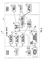
- FIG. 3 is a block diagram showing a control system of one embodiment of the present invention.
- the illustrated embodiment utilizes hardware of a spacecraft 10 and an onboard computer 32.
- a momentum wheel speed sensor 34 provides an electronic signal having a voltage proportional to a speed of each wheel of a momentum system (not shown). There are provided a plurality of speed signals, one speed signal for each wheel in operation. The analog electronic signals are converted to digital form and provided to the onboard computer 32.
- the onboard computer 32 performs a plurality of functions which include: time propagation of an attitude tracking model; conversion of momentum from wheel axes to spacecraft axes; conversion of momentum from spacecraft axes to wheel axes; roll/yaw control; and pitch control.
- a yaw momentum tracking model 40, a roll angle tracking model 42 and a pitch angle tracking model 44 are used by the onboard computer 32 and facilitate generation of desired yaw momentum trajectory H zi , roll angle trajectory ⁇ i and pitch angle trajectory ⁇ i as a function of time.
- Parameters for use in the tracking models are provided in a vector ⁇ and are updated periodically from a ground station (not shown) via conventional telemetry signals provided by a telemetry apparatus 46.
- the functions f 1 , f 2 , and f 3 are general functions which are mission specific, depending upon particular orbits and a pointing path. For highly-accurate pointing missions or large inclination orbits, a full nonlinear kinematic equation must be used. If the spacecraft 10 does not point at the equator, a bias pointing couples with these full nonlinear kinematics to produce a nonsinusoidal trajectory.
- the aim point may move throughout a day.
- the aim point is adjusted to compensate for thermal distortions or minimize a distortion error of independently pointed spot beams.
- the three functions f 1 , f 2 and f 3 are chosen accordingly.
- FIG. 3 includes a momentum measurement distribution matrix 50 and a momentum command distribution matrix 52 which convert wheel speed information to spacecraft momentum and momentum commands to wheel speed commands, respectively.
- the wheel speed commands are provided to a wheel momentum control circuit 54.
- Momentum is stored along a pitch axis and a yaw axis of the spacecraft. This requires at least two nonparallel momentum/reaction wheels in a pitch/yaw plane of a spacecraft. Included among acceptable wheel configurations are the L-wheel system and the V-wheel system described above.
- a roll/yaw control circuit 60 is provided for receipt of the yaw momentum tracking model 40 and the roll angle tracking model 42 outputs, as well as the roll R and measured yaw momentum.
- the roll/yaw control circuit 60 is operable to control magnetic torquers 62 and thrusters 66 of the spacecraft to properly control the aim point.
- a pitch control circuit 70 is provided responsive to an output of the pitch angle tracking model 44, the pitch P, and the measured pitch momentum output from the momentum measurement distribution matrix.
- the pitch control circuit 70 is also operable to control the thrusters 64.
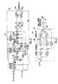
- FIG. 4 is a schematic block diagram of the roll/yaw control circuit 60.
- a measured yaw momentum in the wheels H ⁇ m , an output of a yaw momentum tracking model H zi , an output of a roll angle tracking model ⁇ i , and a roll R from the earth sensor 30 are input into the block diagram.
- the roll angle tracking model 42 output ⁇ i passes through a roll feedforward control block 80.
- this roll feedforward control block 80 is a constant which is equal to a negative H n .
- An output of the roll feedforward control block 80 is added to the output of the yaw momentum tracking model H zi .
- This sum is fed forward and added to an output of a roll control loop 82 and provided to the momentum command distribution matrix 52 to generate a wheel yaw momentum command.
- the sum is also subtracted from a measured yaw momentum and input to both a deadband 84 and a yaw control loop 86.
- the deadband 84 is a threshold which, when exceeded, provides a signal to a yaw thruster of thrusters 64 to fire.
- the roll control loop 82 has a roll error R e ( ⁇ i -R) input. Roll error R e is also provided as an input to the yaw control loop 86.
- FIG. 5 is a block diagram of a specific embodiment of the yaw control loop 86 illustrated in FIG. 4.
- the yaw control loop 86 is described in detail in Lehner et al., incorporated herein by reference and is not discussed here in detail.
- the yaw control loop 86 has two inputs.
- a first input 87 is the roll error R e .
- a second input 89 is the measured yaw momentum in the wheels less the summation of the output of the roll feedforward control and the output of the yaw momentum tracking model 40, H zi .
- Outputs of the yaw control loop 86 are roll and yaw torque commands 91, 93 provided to the magnetic torquers 62, if provided.
- FIG. 6 is a block diagram of a specific embodiment of the roll control loop 82 of FIG. 4 which includes gain elements TM, K and TZ 95, 97, 99 which are calculated from formulas given in the Terasaki publication "Dual Reaction wheel Control With Spacecraft Pointing", Symposium and Attitude Stabilization and Control of Dual Spin Aircraft, August 1967, hereby expressly incorporated by reference for all purposes.
- the output of the roll control loop 82 is fed to a summer 79 (FIG. 4) which is combined with the expression H zi - H n to become a particular of the momentum command distribution matrix.
- FIG. 7 is a block diagram of the pitch control circuit 70.
- An output of the pitch angle tracking model 44, ⁇ i , the pitch angle P from the earth sensor 30 and the measured pitch momentum from the wheels as output by the momentum measurement distribution matrix 50 are fed as inputs to the pitch control circuit 30.
- An angle ⁇ i is provided as an input to a pitch feedforward control circuit 90.
- the pitch angle P from the earth sensor 30 is subtracted from ⁇ i and input to a pitch control loop circuit 90.
- pitch feedforward control 90 is not implemented.
- a pitch error signal P e equal to ⁇ i minus the pitch angle P from the earth sensor 30 is fed into the pitch control loop circuit 92.
- One embodiment of the pitch control loop 92 is shown in FIG. 8.
- Gains K ⁇ and K ⁇ are chosen to place eigenvalues of an optimal estimator 100.
- a controller 102 has gains C ⁇ and C ⁇ which are calculated to place poles of the pitch dynamics. Control system design techniques of this type are standard.
- the output 105 of the controller 102 is fed through a wheel control compensation 104, added to an output of the pitch feedforward control 90 and sent as a pitch momentum command to the momentum command distribution matrix 52.
- a deadband 94 fires a pitch thruster of thrusters 64 when the pitch momentum in the wheels exceeds a preselected threshold. The thrusters provide the torque to point the spacecraft 10.
Landscapes
- Engineering & Computer Science (AREA)
- Remote Sensing (AREA)
- Chemical & Material Sciences (AREA)
- Combustion & Propulsion (AREA)
- Radar, Positioning & Navigation (AREA)
- Aviation & Aerospace Engineering (AREA)
- Automation & Control Theory (AREA)
- Control Of Position, Course, Altitude, Or Attitude Of Moving Bodies (AREA)
Claims (1)
- Verfahren zum Steuern der Haltung eines Raumflugkörpers mit folgenden Schritten:(a) Bestimmen von Ausrichtungsfehlern entlang von wenigstens zwei Achsen des Raumflugkörpers,(b) Empfangen einer allgemeinen Haltungsdefinition für den Raumflugkörper,(c) Erzeugen eines Modells in Antwort auf die allgemeine Haltungsdefinition,(d) Verwenden des Modells, um Haltungsbefehle zu bestimmen,(e) in Antwort auf die Befehle und die Ausrichtungsfehler, Erzeugen einer Haltungssteuerinformation für die Position der Raumflugkörpers, um eine Verfolgung und eine Dämpfung der Nutationsdynamik vorzusehen,(f) Beobachten der langfristige Umlaufbahnratendynamik und Aktualisieren der allgemeinen Haltungsdefinition.
Applications Claiming Priority (5)
| Application Number | Priority Date | Filing Date | Title |
|---|---|---|---|
| US51032190A | 1990-04-16 | 1990-04-16 | |
| US510321 | 1990-04-16 | ||
| US07/579,117 US5100084A (en) | 1990-04-16 | 1990-09-07 | Method and apparatus for inclined orbit attitude control for momentum bias spacecraft |
| US579117 | 1990-09-07 | ||
| EP91302367A EP0453096B1 (de) | 1990-04-16 | 1991-03-19 | Vorrichtung zur Steuerung der Lage eines Satelliten in einer geneigten Umlaufbahn |
Related Parent Applications (2)
| Application Number | Title | Priority Date | Filing Date |
|---|---|---|---|
| EP91302367.7 Division | 1991-03-19 | ||
| EP91302367A Division EP0453096B1 (de) | 1990-04-16 | 1991-03-19 | Vorrichtung zur Steuerung der Lage eines Satelliten in einer geneigten Umlaufbahn |
Publications (2)
| Publication Number | Publication Date |
|---|---|
| EP0769736A1 EP0769736A1 (de) | 1997-04-23 |
| EP0769736B1 true EP0769736B1 (de) | 1999-06-30 |
Family
ID=27056865
Family Applications (3)
| Application Number | Title | Priority Date | Filing Date |
|---|---|---|---|
| EP91302367A Expired - Lifetime EP0453096B1 (de) | 1990-04-16 | 1991-03-19 | Vorrichtung zur Steuerung der Lage eines Satelliten in einer geneigten Umlaufbahn |
| EP94202266A Withdrawn EP0628899A1 (de) | 1990-04-16 | 1991-03-19 | Methode und Vorrichtung zur Steuerung der Lage eines durch Eigenrotation stabilisierten Satelliten in einer geeigneten Umlaufbahn |
| EP96113152A Expired - Lifetime EP0769736B1 (de) | 1990-04-16 | 1991-03-19 | Methode zur Steuerung der Lage eines durch Eigenrotation stabilisierten Satelliten in einer geneigten Umlaufbahn |
Family Applications Before (2)
| Application Number | Title | Priority Date | Filing Date |
|---|---|---|---|
| EP91302367A Expired - Lifetime EP0453096B1 (de) | 1990-04-16 | 1991-03-19 | Vorrichtung zur Steuerung der Lage eines Satelliten in einer geneigten Umlaufbahn |
| EP94202266A Withdrawn EP0628899A1 (de) | 1990-04-16 | 1991-03-19 | Methode und Vorrichtung zur Steuerung der Lage eines durch Eigenrotation stabilisierten Satelliten in einer geeigneten Umlaufbahn |
Country Status (5)
| Country | Link |
|---|---|
| US (1) | US5100084A (de) |
| EP (3) | EP0453096B1 (de) |
| JP (1) | JP3244717B2 (de) |
| CA (1) | CA2040590C (de) |
| DE (2) | DE69126233T2 (de) |
Families Citing this family (57)
| Publication number | Priority date | Publication date | Assignee | Title |
|---|---|---|---|---|
| US5311435A (en) * | 1991-11-27 | 1994-05-10 | Hughes Aircraft Company | Method for station keeping control of flexible spacecraft using onboard gain scheduling scheme |
| US5343398A (en) * | 1992-04-23 | 1994-08-30 | General Electric Co. | Spacecraft roll-yaw compensator with orbit-rate and harmonic bandpass filters |
| US5441222A (en) * | 1993-04-26 | 1995-08-15 | Hughes Aircraft Company | Attitude control of spinning spacecraft |
| US5556058A (en) * | 1994-05-16 | 1996-09-17 | Hughes Electronics | Spacecraft attitude determination using sun sensor, earth sensor, and space-to-ground link |
| EP0790542B1 (de) * | 1995-08-11 | 2000-01-19 | DaimlerChrysler AG | Verfahren zur Lageregelung eines dreiachsenstabilisierten, erdorientierten trägheitsmomentstabilisierten Raumfahrzeuges |
| US5787368A (en) * | 1995-11-03 | 1998-07-28 | Space Systems/Loral, Inc. | Spacecraft yaw control using only wheel speed measurements processed through a simple filter bank |
| US5791598A (en) * | 1996-01-16 | 1998-08-11 | Globalstar L.P. and Daimler-Benz Aerospace AG | Dynamic bias for orbital yaw steering |
| US5738309A (en) * | 1996-02-28 | 1998-04-14 | Hughes Electronics | Single axis correction for orbit inclination |
| US5992799A (en) * | 1996-03-08 | 1999-11-30 | Space Systems/Loral, Inc. | Earth based spacecraft orbit and attitude control using a look-ahead thruster selection logic and magnetic torquers |
| US6047226A (en) * | 1997-06-26 | 2000-04-04 | Hughes Electronics Corporation | Enhanced stellar attitude determination system |
| US6108593A (en) * | 1997-07-09 | 2000-08-22 | Hughes Electronics Corporation | Method and apparatus for estimating attitude sensor bias in a satellite |
| US6154692A (en) * | 1997-10-01 | 2000-11-28 | Space Systems/Loral, Inc. | Spacecraft yaw pointing for inclined orbits |
| US6135389A (en) * | 1998-03-16 | 2000-10-24 | Hughes Electronics Corporation | Subterranean target steering strategy |
| US6047927A (en) * | 1998-03-16 | 2000-04-11 | Honeywell Inc. | Escaping singularities in a satellite attitude control |
| US6288670B1 (en) * | 1999-12-23 | 2001-09-11 | Hughes Electronics Corporation | Combined roll-yaw spacecraft steering method for low earth orbit target trajectory compensation |
| US6292722B1 (en) * | 2000-02-24 | 2001-09-18 | Space Systems/Loral, Inc. | Magnetic torquer control with thruster augmentation |
| US6535734B1 (en) * | 2000-04-04 | 2003-03-18 | Motorola, Inc. | Method and apparatus for steering mobile platform beams |
| US6470243B1 (en) | 2000-06-30 | 2002-10-22 | Hughes Electronics Corp. | Correction of spacecraft steering control law for unexpected orbital inclination effects |
| US6481672B1 (en) | 2001-01-18 | 2002-11-19 | Lockheed Martin Corporation | Gimbaled thruster control system |
| US6732977B1 (en) | 2002-02-11 | 2004-05-11 | Lockheed Martin Corporation | System for on-orbit correction of spacecraft payload pointing errors |
| US6695263B1 (en) | 2002-02-12 | 2004-02-24 | Lockheed Martin Corporation | System for geosynchronous spacecraft rapid earth reacquisition |
| US7051980B2 (en) * | 2002-02-26 | 2006-05-30 | Lockheed Martin Corporation | Efficient orbit sparing system for space vehicle constellations |
| US6702234B1 (en) | 2002-03-29 | 2004-03-09 | Lockheed Martin Corporation | Fault tolerant attitude control system for zero momentum spacecraft |
| US6637701B1 (en) | 2002-04-03 | 2003-10-28 | Lockheed Martin Corporation | Gimbaled ion thruster arrangement for high efficiency stationkeeping |
| US7149610B2 (en) * | 2003-08-26 | 2006-12-12 | The Boeing Company | Momentum estimator for on-station momentum control |
| US7835826B1 (en) | 2005-12-13 | 2010-11-16 | Lockheed Martin Corporation | Attitude determination system for yaw-steering spacecraft |
| KR100793058B1 (ko) * | 2006-09-27 | 2008-01-10 | 한국전자통신연구원 | 지향 목표 궤적 근사화를 이용한 위성 자세 제어 방법 |
| US8205839B2 (en) * | 2006-11-06 | 2012-06-26 | The Boeing Company | Methods and apparatus for node-synchronous eccentricity control |
| US9045239B2 (en) * | 2009-01-14 | 2015-06-02 | Space Systems/Loral, Llc | Spacecraft payload orientation steering |
| US8174433B1 (en) | 2009-02-26 | 2012-05-08 | Raytheon Company | Bias estimation and orbit determination |
| US20110260006A1 (en) * | 2010-01-11 | 2011-10-27 | Cyrus Mohammad Ali Nejat | Nejat kinematics and kinetics expansions spacecraft |
| US8915472B2 (en) | 2012-05-11 | 2014-12-23 | The Boeing Company | Multiple space vehicle launch system |
| US9180984B2 (en) | 2012-05-11 | 2015-11-10 | The Boeing Company | Methods and apparatus for performing propulsion operations using electric propulsion systems |
| CA2831309C (en) * | 2012-12-04 | 2017-05-30 | The Boeing Company | Methods and apparatus for performing propulsion operations using electric propulsion systems |
| CN104252546A (zh) * | 2013-06-26 | 2014-12-31 | 上海新跃仪表厂 | 一种火星捕获制动参数优化方法 |
| FR3033056B1 (fr) * | 2015-02-25 | 2019-05-03 | Centre National D'etudes Spatiales (Cnes) | Procede de determination des parametres de guidage d'un satellite pour suivre une trajectoire |
| CN105138010B (zh) * | 2015-08-31 | 2017-07-28 | 哈尔滨工业大学 | 一种编队卫星分布式有限时间跟踪控制方法 |
| US9641280B1 (en) * | 2015-12-10 | 2017-05-02 | Intelligent Fusion Technology, Inc | Anti-jamming method in satellite communication (SATCOM) system |
| CN109032176B (zh) * | 2018-07-25 | 2021-06-22 | 西北工业大学 | 一种基于微分代数的地球同步轨道确定和参数确定方法 |
| CN109159923B (zh) * | 2018-07-26 | 2022-05-13 | 西北工业大学 | 一种航天器追踪目标丢失段的相对可达区域计算方法 |
| US11279501B2 (en) * | 2018-10-25 | 2022-03-22 | General Atomics | Satellite attitude control system using eigen vector, non-linear dynamic inversion, and feedforward control |
| CN109573105B (zh) * | 2018-11-19 | 2022-06-14 | 上海埃依斯航天科技有限公司 | 末子级留轨应用子系统姿态控制方法 |
| CN110104217A (zh) * | 2019-03-29 | 2019-08-09 | 上海卫星工程研究所 | 卫星姿态控制与大角动量补偿复用飞轮的构形与控制方法 |
| CN110329548B (zh) * | 2019-05-24 | 2023-01-17 | 中国人民解放军63789部队 | 航天器在轨转偏置控制下飞轮系统重构方法 |
| CN111121765B (zh) * | 2019-12-16 | 2021-09-24 | 上海航天控制技术研究所 | 共用遥感卫星平台的对地灵巧观测与对天geo目标监视方法 |
| CN111399531B (zh) * | 2020-04-23 | 2023-04-07 | 中国人民解放军国防科技大学 | 高超声速飞行器滑翔段制导与姿态控制一体化设计方法 |
| CN113238572B (zh) * | 2021-05-31 | 2022-11-22 | 上海海事大学 | 基于预设性能控制的预设时间四旋翼无人机姿态跟踪方法 |
| CN113401365B (zh) * | 2021-06-15 | 2022-05-24 | 北京控制工程研究所 | 倾斜轨道海洋动力卫星高精度轨控过程中的能源控制方法 |
| CN114735239B (zh) * | 2022-04-27 | 2022-10-18 | 中国人民解放军32039部队 | 航天器轨道机动控制方法、装置和电子设备 |
| CN115390447B (zh) * | 2022-08-16 | 2024-05-14 | 哈尔滨逐宇航天科技有限责任公司 | 一种适应姿态大幅机动的飞行器预设性能控制方法 |
| CN116714782B (zh) * | 2023-07-09 | 2025-09-19 | 西北工业大学 | 金字塔型电磁编队的空间失效卫星非接触式变轨操控方法 |
| CN116750211B (zh) * | 2023-07-13 | 2024-01-23 | 四川大学 | 一种基于追踪目标分配与轨道规划的追踪防御方法 |
| CN117985247B (zh) * | 2024-03-15 | 2024-09-13 | 哈尔滨工业大学 | 航天器推力布局及姿轨一体化控制方法 |
| CN118343310B (zh) * | 2024-04-11 | 2025-10-31 | 哈尔滨工业大学 | 考虑时变拓扑和时变时滞的异构航天器编队完全分布式控制方法 |
| CN118387321B (zh) * | 2024-06-19 | 2025-11-28 | 北京航空航天大学 | 一种重力梯度卫星分段最优姿态跟踪控制方法 |
| CN119429180B (zh) * | 2024-10-29 | 2025-11-18 | 北京控制工程研究所 | 一种基于法向量的跟瞄姿态机动路径规划方法 |
| CN120907559B (zh) * | 2025-10-10 | 2025-12-09 | 北京国宇星辰科技有限公司 | 一种对火箭末级近距离绕飞跟踪的态势感知方法 |
Family Cites Families (15)
| Publication number | Priority date | Publication date | Assignee | Title |
|---|---|---|---|---|
| US3088697A (en) * | 1959-12-28 | 1963-05-07 | Bell Telephone Labor Inc | Attitude control for satellite vehicles |
| US3171612A (en) * | 1961-10-06 | 1965-03-02 | Massachusetts Inst Technology | Satellite attitude control mechanism and method |
| US3747095A (en) * | 1970-10-19 | 1973-07-17 | Bell Telephone Labor Inc | Synchronous satellite tracking system |
| US4106094A (en) * | 1976-12-13 | 1978-08-08 | Turpin Systems Company | Strap-down attitude and heading reference system |
| US4084722A (en) * | 1977-05-09 | 1978-04-18 | Continental Can Company, Inc. | Child resistant safety closure |
| FR2393364A1 (fr) * | 1977-05-31 | 1978-12-29 | Aerospatiale | Procede et systeme integre de controle de couple et de conditionnement d'energie pour vehicule spatial |
| US4294420A (en) * | 1978-01-30 | 1981-10-13 | Matra | Attitude control systems for space vehicles |
| US4521855A (en) * | 1981-07-27 | 1985-06-04 | Ford Aerospace & Communications Corporation | Electronic on-orbit roll/yaw satellite control |
| US4630058A (en) * | 1982-02-26 | 1986-12-16 | Rca Corporation | Satellite communication system |
| GB8616385D0 (en) * | 1986-07-04 | 1986-08-13 | Marconi Space Systems Ltd | Satellite attitude control |
| US4757964A (en) * | 1986-07-17 | 1988-07-19 | Hughes Aircraft Company | Method for controlling the attitude of a spinning body in orbit |
| US4776540A (en) * | 1986-10-03 | 1988-10-11 | Communications Satellite Corporation | Method of orienting a synchronous satellite |
| US4911385A (en) * | 1987-04-30 | 1990-03-27 | Agrawal Brij N | Attitude pointing error correction system and method for geosynchronous satellites |
| US4883244A (en) * | 1987-12-23 | 1989-11-28 | Hughes Aircraft Company | Satellite attitude determination and control system with agile beam sensing |
| FR2637565B1 (fr) * | 1988-10-06 | 1991-01-11 | Aerospatiale | Systeme de controle actif selon trois axes de l'attitude d'un satellite geostationnaire |
-
1990
- 1990-09-07 US US07/579,117 patent/US5100084A/en not_active Expired - Fee Related
-
1991
- 1991-03-19 DE DE69126233T patent/DE69126233T2/de not_active Expired - Fee Related
- 1991-03-19 EP EP91302367A patent/EP0453096B1/de not_active Expired - Lifetime
- 1991-03-19 DE DE69131405T patent/DE69131405T2/de not_active Expired - Fee Related
- 1991-03-19 EP EP94202266A patent/EP0628899A1/de not_active Withdrawn
- 1991-03-19 EP EP96113152A patent/EP0769736B1/de not_active Expired - Lifetime
- 1991-04-16 CA CA002040590A patent/CA2040590C/en not_active Expired - Fee Related
- 1991-04-16 JP JP10954691A patent/JP3244717B2/ja not_active Expired - Fee Related
Also Published As
| Publication number | Publication date |
|---|---|
| DE69131405T2 (de) | 1999-12-16 |
| CA2040590A1 (en) | 1991-10-17 |
| DE69126233D1 (de) | 1997-07-03 |
| EP0628899A1 (de) | 1994-12-14 |
| DE69126233T2 (de) | 1997-11-27 |
| DE69131405D1 (de) | 1999-08-05 |
| EP0453096B1 (de) | 1997-05-28 |
| EP0453096A1 (de) | 1991-10-23 |
| JPH0789499A (ja) | 1995-04-04 |
| CA2040590C (en) | 1999-07-27 |
| US5100084A (en) | 1992-03-31 |
| JP3244717B2 (ja) | 2002-01-07 |
| EP0769736A1 (de) | 1997-04-23 |
Similar Documents
| Publication | Publication Date | Title |
|---|---|---|
| EP0769736B1 (de) | Methode zur Steuerung der Lage eines durch Eigenrotation stabilisierten Satelliten in einer geneigten Umlaufbahn | |
| US8113468B2 (en) | Precision attitude control system for gimbaled thruster | |
| US5791598A (en) | Dynamic bias for orbital yaw steering | |
| US5349532A (en) | Spacecraft attitude control and momentum unloading using gimballed and throttled thrusters | |
| US6481672B1 (en) | Gimbaled thruster control system | |
| US5149022A (en) | Satellite roll and yaw attitude control method | |
| US5692707A (en) | Universal spacecraft attitude steering control system | |
| US5540405A (en) | Method and apparatus for compensating for magnetic disturbance torques on a satellite | |
| EP0683098A1 (de) | System zur Bestimmung der Lage eines Raumfahrzeuges mittels eines Sonnensensors, eines Erdsensors und einer Weltraum-Erd-Verbindung | |
| EP0792800A1 (de) | Einachsige Korrektur für Bahnneigung | |
| US6615117B2 (en) | Attitude determination system and method with outer-loop gyro scale-factor non-linearity calibration | |
| US7437224B2 (en) | Target acquisition control for spacecraft gimballed payload | |
| US5996942A (en) | Autonomous solar torque management | |
| EP0544241A1 (de) | Methode und Vorrichtung zur dynamischen Prekompensation von Rückwirkungen der Schrittbewegung eines Solarpaneels auf einen Satelliten | |
| BAUER et al. | Attitude control system conceptual design for the X-ray timing explorer | |
| Chubb | Stabilization and control of the Apollo Telescope Mount | |
| Rodden | Attitude control using momentum wheels | |
| Price et al. | Flight experience of dynamic momentum bias for spacecraft yaw steering | |
| Chubb | Skylab's Apollo telescope mount | |
| MUHLFELDER | Attitude Control System evolution of body-stabilized communication spacecraft |
Legal Events
| Date | Code | Title | Description |
|---|---|---|---|
| PUAI | Public reference made under article 153(3) epc to a published international application that has entered the european phase |
Free format text: ORIGINAL CODE: 0009012 |
|
| 17P | Request for examination filed |
Effective date: 19960906 |
|
| AC | Divisional application: reference to earlier application |
Ref document number: 453096 Country of ref document: EP |
|
| AK | Designated contracting states |
Kind code of ref document: A1 Designated state(s): DE FR GB IT |
|
| 17Q | First examination report despatched |
Effective date: 19980130 |
|
| GRAG | Despatch of communication of intention to grant |
Free format text: ORIGINAL CODE: EPIDOS AGRA |
|
| GRAG | Despatch of communication of intention to grant |
Free format text: ORIGINAL CODE: EPIDOS AGRA |
|
| GRAH | Despatch of communication of intention to grant a patent |
Free format text: ORIGINAL CODE: EPIDOS IGRA |
|
| GRAH | Despatch of communication of intention to grant a patent |
Free format text: ORIGINAL CODE: EPIDOS IGRA |
|
| GRAA | (expected) grant |
Free format text: ORIGINAL CODE: 0009210 |
|
| AC | Divisional application: reference to earlier application |
Ref document number: 453096 Country of ref document: EP |
|
| AK | Designated contracting states |
Kind code of ref document: B1 Designated state(s): DE FR GB IT |
|
| REF | Corresponds to: |
Ref document number: 69131405 Country of ref document: DE Date of ref document: 19990805 |
|
| ET | Fr: translation filed | ||
| PLBE | No opposition filed within time limit |
Free format text: ORIGINAL CODE: 0009261 |
|
| STAA | Information on the status of an ep patent application or granted ep patent |
Free format text: STATUS: NO OPPOSITION FILED WITHIN TIME LIMIT |
|
| 26N | No opposition filed | ||
| REG | Reference to a national code |
Ref country code: GB Ref legal event code: IF02 |
|
| PGFP | Annual fee paid to national office [announced via postgrant information from national office to epo] |
Ref country code: FR Payment date: 20030304 Year of fee payment: 13 |
|
| PGFP | Annual fee paid to national office [announced via postgrant information from national office to epo] |
Ref country code: GB Payment date: 20030312 Year of fee payment: 13 |
|
| PGFP | Annual fee paid to national office [announced via postgrant information from national office to epo] |
Ref country code: DE Payment date: 20030331 Year of fee payment: 13 |
|
| PG25 | Lapsed in a contracting state [announced via postgrant information from national office to epo] |
Ref country code: GB Free format text: LAPSE BECAUSE OF NON-PAYMENT OF DUE FEES Effective date: 20040319 |
|
| PG25 | Lapsed in a contracting state [announced via postgrant information from national office to epo] |
Ref country code: DE Free format text: LAPSE BECAUSE OF NON-PAYMENT OF DUE FEES Effective date: 20041001 |
|
| GBPC | Gb: european patent ceased through non-payment of renewal fee |
Effective date: 20040319 |
|
| PG25 | Lapsed in a contracting state [announced via postgrant information from national office to epo] |
Ref country code: FR Free format text: LAPSE BECAUSE OF NON-PAYMENT OF DUE FEES Effective date: 20041130 |
|
| REG | Reference to a national code |
Ref country code: FR Ref legal event code: ST |
|
| PG25 | Lapsed in a contracting state [announced via postgrant information from national office to epo] |
Ref country code: IT Free format text: LAPSE BECAUSE OF NON-PAYMENT OF DUE FEES Effective date: 20050319 |