EP0347499A1 - Verfahren zur Herstellung einer oszillierenden Andruckwalze, die für die Verdrängung im Blasverfahren hergestellter Kunststoff-Schlauchfolien benutzt wird - Google Patents
Verfahren zur Herstellung einer oszillierenden Andruckwalze, die für die Verdrängung im Blasverfahren hergestellter Kunststoff-Schlauchfolien benutzt wird Download PDFInfo
- Publication number
- EP0347499A1 EP0347499A1 EP88305682A EP88305682A EP0347499A1 EP 0347499 A1 EP0347499 A1 EP 0347499A1 EP 88305682 A EP88305682 A EP 88305682A EP 88305682 A EP88305682 A EP 88305682A EP 0347499 A1 EP0347499 A1 EP 0347499A1
- Authority
- EP
- European Patent Office
- Prior art keywords
- web
- rollers
- spindle
- center line
- roller
- Prior art date
- Legal status (The legal status is an assumption and is not a legal conclusion. Google has not performed a legal analysis and makes no representation as to the accuracy of the status listed.)
- Granted
Links
- 238000001125 extrusion Methods 0.000 title description 14
- 238000000034 method Methods 0.000 title description 11
- 230000003534 oscillatory effect Effects 0.000 claims abstract description 12
- 239000004033 plastic Substances 0.000 claims description 7
- 238000007665 sagging Methods 0.000 claims description 6
- 230000033001 locomotion Effects 0.000 claims description 5
- 229920001971 elastomer Polymers 0.000 claims description 4
- 230000000694 effects Effects 0.000 claims description 3
- 239000000806 elastomer Substances 0.000 claims description 2
- 244000182067 Fraxinus ornus Species 0.000 claims 1
- 239000011248 coating agent Substances 0.000 claims 1
- 238000000576 coating method Methods 0.000 claims 1
- 238000012544 monitoring process Methods 0.000 claims 1
- 230000002441 reversible effect Effects 0.000 claims 1
- 241001131696 Eurystomus Species 0.000 description 65
- 230000007246 mechanism Effects 0.000 description 15
- 239000002985 plastic film Substances 0.000 description 6
- 229920006255 plastic film Polymers 0.000 description 6
- 230000008569 process Effects 0.000 description 6
- 238000004519 manufacturing process Methods 0.000 description 4
- 230000008859 change Effects 0.000 description 3
- 230000010355 oscillation Effects 0.000 description 3
- 238000004804 winding Methods 0.000 description 3
- 206010043268 Tension Diseases 0.000 description 2
- 230000007423 decrease Effects 0.000 description 2
- 238000009826 distribution Methods 0.000 description 2
- 239000002356 single layer Substances 0.000 description 2
- 206010009192 Circulatory collapse Diseases 0.000 description 1
- 208000036366 Sensation of pressure Diseases 0.000 description 1
- 230000001133 acceleration Effects 0.000 description 1
- 230000009471 action Effects 0.000 description 1
- 230000005540 biological transmission Effects 0.000 description 1
- 230000015572 biosynthetic process Effects 0.000 description 1
- 238000003490 calendering Methods 0.000 description 1
- 238000005266 casting Methods 0.000 description 1
- 238000007796 conventional method Methods 0.000 description 1
- 238000012937 correction Methods 0.000 description 1
- 230000001186 cumulative effect Effects 0.000 description 1
- 230000007547 defect Effects 0.000 description 1
- 230000001419 dependent effect Effects 0.000 description 1
- 238000011161 development Methods 0.000 description 1
- 238000005755 formation reaction Methods 0.000 description 1
- 239000010410 layer Substances 0.000 description 1
- 238000012986 modification Methods 0.000 description 1
- 230000004048 modification Effects 0.000 description 1
- 230000002093 peripheral effect Effects 0.000 description 1
- 229920000642 polymer Polymers 0.000 description 1
- 229920000136 polysorbate Polymers 0.000 description 1
- 230000000717 retained effect Effects 0.000 description 1
Images


Classifications
-
- B—PERFORMING OPERATIONS; TRANSPORTING
- B65—CONVEYING; PACKING; STORING; HANDLING THIN OR FILAMENTARY MATERIAL
- B65H—HANDLING THIN OR FILAMENTARY MATERIAL, e.g. SHEETS, WEBS, CABLES
- B65H23/00—Registering, tensioning, smoothing or guiding webs
- B65H23/02—Registering, tensioning, smoothing or guiding webs transversely
- B65H23/0204—Sensing transverse register of web
- B65H23/0216—Sensing transverse register of web with an element utilising photoelectric effect
-
- B—PERFORMING OPERATIONS; TRANSPORTING
- B29—WORKING OF PLASTICS; WORKING OF SUBSTANCES IN A PLASTIC STATE IN GENERAL
- B29C—SHAPING OR JOINING OF PLASTICS; SHAPING OF MATERIAL IN A PLASTIC STATE, NOT OTHERWISE PROVIDED FOR; AFTER-TREATMENT OF THE SHAPED PRODUCTS, e.g. REPAIRING
- B29C48/00—Extrusion moulding, i.e. expressing the moulding material through a die or nozzle which imparts the desired form; Apparatus therefor
- B29C48/03—Extrusion moulding, i.e. expressing the moulding material through a die or nozzle which imparts the desired form; Apparatus therefor characterised by the shape of the extruded material at extrusion
- B29C48/09—Articles with cross-sections having partially or fully enclosed cavities, e.g. pipes or channels
- B29C48/10—Articles with cross-sections having partially or fully enclosed cavities, e.g. pipes or channels flexible, e.g. blown foils
-
- B—PERFORMING OPERATIONS; TRANSPORTING
- B29—WORKING OF PLASTICS; WORKING OF SUBSTANCES IN A PLASTIC STATE IN GENERAL
- B29C—SHAPING OR JOINING OF PLASTICS; SHAPING OF MATERIAL IN A PLASTIC STATE, NOT OTHERWISE PROVIDED FOR; AFTER-TREATMENT OF THE SHAPED PRODUCTS, e.g. REPAIRING
- B29C53/00—Shaping by bending, folding, twisting, straightening or flattening; Apparatus therefor
- B29C53/02—Bending or folding
- B29C53/10—Bending or folding of blown tubular films, e.g. gusseting
-
- B—PERFORMING OPERATIONS; TRANSPORTING
- B29—WORKING OF PLASTICS; WORKING OF SUBSTANCES IN A PLASTIC STATE IN GENERAL
- B29C—SHAPING OR JOINING OF PLASTICS; SHAPING OF MATERIAL IN A PLASTIC STATE, NOT OTHERWISE PROVIDED FOR; AFTER-TREATMENT OF THE SHAPED PRODUCTS, e.g. REPAIRING
- B29C53/00—Shaping by bending, folding, twisting, straightening or flattening; Apparatus therefor
- B29C53/16—Straightening or flattening
- B29C53/20—Straightening or flattening of tubes
-
- B—PERFORMING OPERATIONS; TRANSPORTING
- B65—CONVEYING; PACKING; STORING; HANDLING THIN OR FILAMENTARY MATERIAL
- B65H—HANDLING THIN OR FILAMENTARY MATERIAL, e.g. SHEETS, WEBS, CABLES
- B65H23/00—Registering, tensioning, smoothing or guiding webs
- B65H23/04—Registering, tensioning, smoothing or guiding webs longitudinally
- B65H23/32—Arrangements for turning or reversing webs
-
- B—PERFORMING OPERATIONS; TRANSPORTING
- B29—WORKING OF PLASTICS; WORKING OF SUBSTANCES IN A PLASTIC STATE IN GENERAL
- B29C—SHAPING OR JOINING OF PLASTICS; SHAPING OF MATERIAL IN A PLASTIC STATE, NOT OTHERWISE PROVIDED FOR; AFTER-TREATMENT OF THE SHAPED PRODUCTS, e.g. REPAIRING
- B29C48/00—Extrusion moulding, i.e. expressing the moulding material through a die or nozzle which imparts the desired form; Apparatus therefor
- B29C48/001—Combinations of extrusion moulding with other shaping operations
- B29C48/0018—Combinations of extrusion moulding with other shaping operations combined with shaping by orienting, stretching or shrinking, e.g. film blowing
-
- B—PERFORMING OPERATIONS; TRANSPORTING
- B29—WORKING OF PLASTICS; WORKING OF SUBSTANCES IN A PLASTIC STATE IN GENERAL
- B29C—SHAPING OR JOINING OF PLASTICS; SHAPING OF MATERIAL IN A PLASTIC STATE, NOT OTHERWISE PROVIDED FOR; AFTER-TREATMENT OF THE SHAPED PRODUCTS, e.g. REPAIRING
- B29C48/00—Extrusion moulding, i.e. expressing the moulding material through a die or nozzle which imparts the desired form; Apparatus therefor
- B29C48/001—Combinations of extrusion moulding with other shaping operations
- B29C48/0019—Combinations of extrusion moulding with other shaping operations combined with shaping by flattening, folding or bending
-
- B—PERFORMING OPERATIONS; TRANSPORTING
- B65—CONVEYING; PACKING; STORING; HANDLING THIN OR FILAMENTARY MATERIAL
- B65H—HANDLING THIN OR FILAMENTARY MATERIAL, e.g. SHEETS, WEBS, CABLES
- B65H2404/00—Parts for transporting or guiding the handled material
- B65H2404/10—Rollers
- B65H2404/15—Roller assembly, particular roller arrangement
- B65H2404/152—Arrangement of roller on a movable frame
- B65H2404/1521—Arrangement of roller on a movable frame rotating, pivoting or oscillating around an axis, e.g. parallel to the roller axis
- B65H2404/15212—Arrangement of roller on a movable frame rotating, pivoting or oscillating around an axis, e.g. parallel to the roller axis rotating, pivoting or oscillating around an axis perpendicular to the roller axis
-
- B—PERFORMING OPERATIONS; TRANSPORTING
- B65—CONVEYING; PACKING; STORING; HANDLING THIN OR FILAMENTARY MATERIAL
- B65H—HANDLING THIN OR FILAMENTARY MATERIAL, e.g. SHEETS, WEBS, CABLES
- B65H2553/00—Sensing or detecting means
- B65H2553/40—Sensing or detecting means using optical, e.g. photographic, elements
- B65H2553/41—Photoelectric detectors
Definitions
- the present invention relates to a web handling apparatus and particularly relates to an oscillating pinch roll assembly utilized in conjuction with the extrusion of blown plastic films.
- the roll formation or the characteristic shape of a cylindrical roll of the film is a very important characteristic indicative of the overall quality of the film. This is especially true with soft and light gauge films that are commercially sold in a roll form.
- a perfect or near perfect cylindrically shaped roll is a mandatory requirement for many plastic film applications and uses.
- a perfect cylindrically shaped roll implies a perfect uniform gauge across the plastic film or web. This uniform gauge is very difficult to obtain in films made by a casting or made by calendering process. In te extrusion of plastic films, it is virtually impossible to obtain a uniform film gauge that will, in turn, produce a uniform, cylindrical roll. This is especially true due to the nature of the gauge variations in the web (i.e., the film) which are very localized in the cross machine direction.
- these high and low gauge sections add up algebraically thereby deforming the outer contour of the cylindrical roll; hence, "high bands” and “valleys” are readily identified in the roll. This condition affects the flatness of the web when the film is unrolled.
- the resulting double walled web can be wound as a "lay flat", can be slit on both edges and wound on two rolls each carrying a single layer of film, or can be slit at one point and then opened to obtain one single layer roll having a width double that of the lay flat.
- any particular longitudinal line of the plastic bubble remains in the same lateral location of the finished roll of film as it was in the original tubular web.
- This longitudinal imperfection or defect produces a bad or uneven cylindrical roll due to the cumulative effect of this gauge variation.
- the constant, longitudinal, imperfect gauge variation line in the bubble will change its relative position across the lateral width of the roll of film. If the pinch rolls are rotated slowly and at a uniform rather through a 360 degree angle, each and every line or imperfection in the bubble traverses the full lateral width of the web. This produces as even distribution of any imperfections in the film gauge across the web. For simplicity of power transmission, by reversing the rotation of the pinch rolls and counter rotating them 360 degrees in the opposite direction, in the same slow and uniform rate, the imperfections are further laterally distributed over the longitudinal run of the web.
- this technique of rotating the pinch rollers with respect to the center line of the bubble has been applied in many different ways to obtain the lateral distribution of film gauge variations over a longitudinal run of the film.
- the winder and the pinch rolls have been oscillated about the bubble center line when the extruder is stationary, with the winder or the extruder on the vertically upper top of the extrusion apparatus.
- Another method is to rotate the extruder about the extrusion or bubble center line while keeping the pinch rollers and winder stationary.
- Vertical extruders mounted on a rotating base were developed to save floor space in the manufacturing facility.
- rotational dies have been widely used to generate a rotation between the pinch rollers and the tubular web.
- One device was developed in which a stationary extruder, die and winder were used with only the pinch rollers being oscillated about the bubble center line.
- An idler roller was mounted with the pinch rollers parallel to the pinch rollers and positioned outwardly and slightly higher than the pinch rollers.
- a turn bar was horizontally located near and rotatable about the extrusion or bubble center line. This turn bar oscillated at one-half the angular speed of the pinch rolls. The trajectory of the lay flat over this idler roll and turn bar made a 180 degree turn.
- the output path of the web was stabilized by fixing it over one stationary idler roller and bringing the web down from the tower (upon which was located the pinch rollers and web handler) to the stationary winder.
- the oscillation of the pinch rollers was 180 degrees and this technique produced good results with a reasonable good gauge control.
- U.S. Patent No. 3,657,974 by Hedrich, et al. discloses the use of a pinch roller mechanism having a turn bar coplanarly turning the flattened web and two deflecting rollers at one axial end of the turn bar.
- the axis of rotation of this pair of deflecting rollers is parallel to the center axis of the tubular web.
- a third withholding roller having an axis of rotation parallel to the tubular web center axis, is disposed at the other axial end of the turn bar.
- the flattened and turned web runs between the first pair of deflecting rollers, over one roller of that pair of deflecting rollers and to a fixed deflecting roller.
- the pinch rollers, turning bar and three deflecting rollers are rotated 360 degrees such that the web still passes between the pair of deflecting rollers, but then passes over the pair of deflecting rollers and is spaced from the turn bar by the third deflecting roller at the other axial end of the turning bar.
- the unsupported distance transversed by the web is significant, i.e., the distance between the pair of deflecting rollers and the stationary idler roller.
- the oscillatory motion is at a constant speed, change in the speed of the web will not be constant because of the straight line distance between the pair of deflecting rollers and the fixed roller varies disproportionately as compared to the oscillatory speed.
- the oscillating pinch roll assembly or web handling apparatus includes a rotatable spindle having an input which accepts the tubular web from the extruder.
- a pinch roller is mounted at the input of the spindle which pulls the web into the spindle.
- a plurality of rollers are circumferentially disposed around the pinch roller and the axis of rotation of those rollers is parallel to the center line of the tubular web.
- a turning bar is disposed in the interior of the spindle and turns the flattened web exiting the pinch rollers 90 degrees and feeds the horizontal traveling web to a first roller of the plurality of rollers disposed at the periphery of the spindle. The traveling web always passes over this first roller.
- the horizontally traveling, flat web is wound and unwound around the outer periphery of the spindle and is fed continuously to a fixed position that is occupied by an idler roller.
- Means is provided for askewing the plurality of rollers such that their axis of rotation is not perfectly parallel to the center line of the tubular web.
- the axis rotation of the rollers is changed such that an upward force is imparted to the web traveling over the rollers and hence any sag between rollers is compensated for.
- the present invention relates to an oscillating pinch roll assembly utilized in conjunction with the extrusion of blown films and a method of handling the tubular web obtained from that extrusion process.
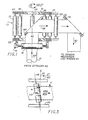
- FIG 1 is a schematic side view of the apparatus generally from the perspective section line 1′-′ ⁇ in Figure 2A.
- Tubular web 10 is pulled into a rotatable spindle structure 12 by pinch rollers 14.
- the pinch rollers are comprised of rollers 15 and 17 best illustrated in Figure 2A. These pinch rollers are driven by motor 16 which is also mounted on spindle 12.
- the axis of rotation of rollers 15 and 17 is normal to the center line of tubular web 10, that center line shown as imaginary line 19 in Figure 1.
- spindle 12 is generally defined by lower circular support structure 20, a plurality of rollers 22, 24 , 26, 28, 30, 32, 34 and 36 upper circular support structure 40 that mates with the peripheral edge of circular support structure 41.
- Support structures 20, 40 and 41 are rotatably mounted by an appropriate means to a frame or other structure which, in this embodiment, is vertically atop a bubble extruder 42.
- a bubble extruder For a general description of such a bubble extruder, reference is made herein to U.S. Patent No. 3,657,974 to Hedrich, et al., and that disclosure is incorporated herein by reference thereto.
- a turning bar 44 is mounted in the interior of spindle 12 and affixed to frame 46.
- Frame 46 is attached to lower support structure 20 and to the upper, inner support structure 41, in Figure 5.
- Turning bar 44 is disposed in the plane of the flattened web 62 (the double walled film or web obtained by flattening tubular web 10 by pinch rollers 14).
- the bar coplanarly turns flattened web 62 substantially 90 degrees as shown by comparison of arrows 64 and 66. After being turned 90 degrees, in this embodiment to a horizontal position, web 62 travels over roller 22 and then travels over fixed roller 68. Roller 68 is not part of the rotatable spindle 12 since it is attached to the stationary frame structure shown in broken away cross-section in Figure 1.
- edge sensor 74 After leaving stationary roller 68, edge sensor 74 detects the sag of horizontally traveling web and sag control 470 produces a signal which is fed back into askew control mechanism described later with respect to Figure 4.
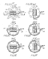
- FIG. 5 shows a partial, plan view of a mechanism for imparting oscillatory motion to upper out, upper inner and lower support structures 40, 41 and 20.
- Lower support structure 20 has a tapered groove 221 downwardly open on its bottom surface 223.
- a driving wheel 272 has a tapered edge 273 that mates with groove 221.
- Wheel 272 is connected to shaft 275 that rotates in two directions as shown by double-headed arrow 277.
- Roller 30 is mounted on roller shaft 279.
- the lower section 281 of the shaft is held in cavity 283.
- the upper section 285 is retained by a self-aligning axial bearing 287.
- Lower support structure 20 is also supported by two idler wheels, not shown, such that all of the wheels (the drive and idler) are 120 degrees apart.
- Web 62 traveling in direction 66 then passes over stationary turning bar 78 and is again turned 90 degrees such that is moves downward in direction 80 towards tension mechanism and winder means 84.
- the tensioning mechanism although not shown could be a dancer roll within the tension mechanism and winder means 84 which is simply the winder upon which the finished cylindrical roll is formed.
- Spindle 12 can be though of as a spool which winds and unwinds flattened web 62 about its outer periphery.
- Figure 2A shows the 0 degrees angular position wherein roller 22 is closely spaced from fixed roller 68. At a minimum, spool 12 must include roller 22 and roller 30 at diametrically opposing positions on the spindle.
- Spindle 12 slowly rotates clockwise in direction 102 was shown in Figures 2B through 2E. Those figures show sequentially the 90 degree position, 180 degree position, 270 degree position and 360 degree position. It can be seen that pinch rollers 14 and turning bar 44 rotate about center line 19 of tubular web 10. After rotating through the predetermined 360 degree angle shown in Figure 2E, the spindle mechanism is counter rotated as shown in Figure 2f, counter clockwise or in direction 104 and web 62 is unwound from spindle 12.
- web 62 leaves stationary roller 68 at the same position and in the same direction. This direction is immediately to the right of stationary roller 68 as shown in Figures 2A through 2F.
- the web can alterna tively travel along path 106 as shown by the dash lines in Figure 2C. In either case, the web travels in the same direction.
- web 62 always travels over the first roller 22 that defines a portion of the periphery of spindle 12 and further periodically travels over all other rollers mounted on the spindle. The rollers always turn in the same direction notwithstanding the winding and unwinding direction of the spindle in general.
- the oscillation of the spindle is very slow as compared with the speed of travel of web 62. For example, a speed of 0.04-0.08 RPM is not uncommon for the spindle. Since the distance the flattened web must travel increases and decreases dependent upon the winding or unwinding position of the spindle, the change in web speed is almost constant.
- Tensioning mechanism 82 is downstream of the web handling apparatus. That tensioning mechanism affects the take-up winder speed or velocity as well as the tension of the web coming off of the spindle and associated structures. Further, the increase and decrease in speed is minimal as compared with the traveling speed of the web.
- the tension on the web is adjustable and an optimum amount is applied for proper operation of the web handling apparatus by tension mechanism 82 identified in Figure 1.
- Rollers 22, 24, 26, 28, 30, 32, 34, 36 and 68 can be coated with rubber or other elastomer with a high coefficient of friction. In this manner, no slippage occurs between the rollers and the web. If eight rollers are used, the effect of sagging is relatively minor due to the small distance between the rollers. However, the effect of any sagging can be completely eliminated or nullified by tilting or askewing the axis of the rollers from the line parallel to the center line of the tubular web (center line 19 in Figure 1).
- Figure 3 details this tilting or askewing.
- Center line 19 is parallel to the center line of the tubular web.
- the upper support 40 and lower support structure 20 is shown in the Figure.
- the axis of rotation of roller 112 is changed to center line 114.
- an angle exists between parallel center line 19 and current posi tion center line 114.
- the web travels normal to that axis of rotation as shown by the dash lines in Figure 3.
- roller 112 has an axially center line 114, the web experiences an upward movement because the web attempts to travel in a line normal to the axis of rotation of that roller.
- the sagging can be automatically adjusted utilizing edge detector 74 and sag control 470 shown in Figure 6.
- the sag control produces an angle signal that is applied to a device shown in detail in Figure 4.
- the sag control signal is applied to hydraulic sag control unit 470.
- Rod 473 is connected to outer, upper support structure 40 whereas cylinder 471 is connected to inner, upper support structure 41.
- They hydraulic actuator is a two cylinder device operable in opposing directions, i.e., the cylinders are in series.
- Figure 6 shows a plan view of hydraulic cylinder 471 atop support 41 and oscillatory drive wheel 272 below support 20.
- Figure 7 shows a top view with cylinders 471A and 471B operable to control the askew of each roller that is shown by dashed lines.
- the blown film extrusion process is done at a constant speed.
- the lineal speed of the bubble, surface speed of the pinch rollers and the speed of lay flat traveling through the assembly and over the rollers defining the spindle is constant in relation to the assembly.
- the number of rollers defining the outer periphery of the spindle can be changed.
- the driving mechanisms of the spindle and of the pinch rollers can be altered.
- the edge sensor, the sag control and askew or tilting control can be modified and can be moved to any particular location that may provide an indication of sag of the horizontally traveling web.
- the spindle need not be vertically aligned, but must be aligned with the center line of the tubular web.
- the axial center line of the spindle must be horizontal and the flattened web would travel circumferentially about that horizontal axis. In that case, the sag control mechamism may not be necessary.
Landscapes
- Engineering & Computer Science (AREA)
- Mechanical Engineering (AREA)
- Registering, Tensioning, Guiding Webs, And Rollers Therefor (AREA)
- Shaping By String And By Release Of Stress In Plastics And The Like (AREA)
- Shaping Of Tube Ends By Bending Or Straightening (AREA)
Priority Applications (4)
| Application Number | Priority Date | Filing Date | Title |
|---|---|---|---|
| US07/028,866 US4760627A (en) | 1987-03-23 | 1987-03-23 | Apparatus for an oscillating pinch roll assembly utilized in the extrusion of blown films |
| DE88305682T DE3880670T2 (de) | 1988-06-22 | 1988-06-22 | Verfahren zur Herstellung einer oszillierenden Andruckwalze, die für die Verdrängung im Blasverfahren hergestellter Kunststoff-Schlauchfolien benutzt wird. |
| EP88305682A EP0347499B1 (de) | 1988-06-22 | 1988-06-22 | Verfahren zur Herstellung einer oszillierenden Andruckwalze, die für die Verdrängung im Blasverfahren hergestellter Kunststoff-Schlauchfolien benutzt wird |
| ES198888305682T ES2041797T3 (es) | 1988-06-22 | 1988-06-22 | Procedimiento y aparato para un conjunto de rodillos de presion oscilante utilizado en la extrusion por soplado de peliculas. |
Applications Claiming Priority (1)
| Application Number | Priority Date | Filing Date | Title |
|---|---|---|---|
| EP88305682A EP0347499B1 (de) | 1988-06-22 | 1988-06-22 | Verfahren zur Herstellung einer oszillierenden Andruckwalze, die für die Verdrängung im Blasverfahren hergestellter Kunststoff-Schlauchfolien benutzt wird |
Publications (2)
| Publication Number | Publication Date |
|---|---|
| EP0347499A1 true EP0347499A1 (de) | 1989-12-27 |
| EP0347499B1 EP0347499B1 (de) | 1993-04-28 |
Family
ID=8200111
Family Applications (1)
| Application Number | Title | Priority Date | Filing Date |
|---|---|---|---|
| EP88305682A Expired - Lifetime EP0347499B1 (de) | 1987-03-23 | 1988-06-22 | Verfahren zur Herstellung einer oszillierenden Andruckwalze, die für die Verdrängung im Blasverfahren hergestellter Kunststoff-Schlauchfolien benutzt wird |
Country Status (3)
| Country | Link |
|---|---|
| EP (1) | EP0347499B1 (de) |
| DE (1) | DE3880670T2 (de) |
| ES (1) | ES2041797T3 (de) |
Cited By (4)
| Publication number | Priority date | Publication date | Assignee | Title |
|---|---|---|---|---|
| EP0522536A1 (de) * | 1991-07-12 | 1993-01-13 | Barmag Ag | Blasfolienanlage |
| WO2006125586A1 (de) * | 2005-05-23 | 2006-11-30 | Windmöller & Hölscher Kg | Umlenkeinrichtung für eine folienbahn |
| CN105775865A (zh) * | 2016-04-18 | 2016-07-20 | 苏州九高科无纺设备有限公司 | 一种折布架及其折布方法 |
| CN116040379A (zh) * | 2023-02-20 | 2023-05-02 | 句容市平凡节能材料有限公司 | 一种装饰材料覆网机及其覆网的方法 |
Citations (4)
| Publication number | Priority date | Publication date | Assignee | Title |
|---|---|---|---|---|
| FR1553853A (de) * | 1966-11-12 | 1969-01-17 | ||
| DE2800262A1 (de) * | 1978-01-04 | 1979-07-05 | Reifenhaeuser Kg | Vorrichtung zum flachlegen und abziehen einer kunststoffschlauchfolie |
| DE3100520A1 (de) * | 1979-07-14 | 1982-08-12 | Mannesmann Demag Kunstofftechnik Zweigniederlassung der Mannesmann Demag AG, 8500 Nürnberg | Flachlege- und abzugsvorrichtung fuer im blasverfahren hergestellte kunststoff-schlauchfolien |
| EP0252671A1 (de) * | 1986-07-08 | 1988-01-13 | Mirek Planeta | Vorrichtung zum Dickenausgleich bei Kunststoffolienschläuchen |
-
1988
- 1988-06-22 ES ES198888305682T patent/ES2041797T3/es not_active Expired - Lifetime
- 1988-06-22 EP EP88305682A patent/EP0347499B1/de not_active Expired - Lifetime
- 1988-06-22 DE DE88305682T patent/DE3880670T2/de not_active Expired - Fee Related
Patent Citations (4)
| Publication number | Priority date | Publication date | Assignee | Title |
|---|---|---|---|---|
| FR1553853A (de) * | 1966-11-12 | 1969-01-17 | ||
| DE2800262A1 (de) * | 1978-01-04 | 1979-07-05 | Reifenhaeuser Kg | Vorrichtung zum flachlegen und abziehen einer kunststoffschlauchfolie |
| DE3100520A1 (de) * | 1979-07-14 | 1982-08-12 | Mannesmann Demag Kunstofftechnik Zweigniederlassung der Mannesmann Demag AG, 8500 Nürnberg | Flachlege- und abzugsvorrichtung fuer im blasverfahren hergestellte kunststoff-schlauchfolien |
| EP0252671A1 (de) * | 1986-07-08 | 1988-01-13 | Mirek Planeta | Vorrichtung zum Dickenausgleich bei Kunststoffolienschläuchen |
Cited By (6)
| Publication number | Priority date | Publication date | Assignee | Title |
|---|---|---|---|---|
| EP0522536A1 (de) * | 1991-07-12 | 1993-01-13 | Barmag Ag | Blasfolienanlage |
| WO2006125586A1 (de) * | 2005-05-23 | 2006-11-30 | Windmöller & Hölscher Kg | Umlenkeinrichtung für eine folienbahn |
| US9169098B2 (en) | 2005-05-23 | 2015-10-27 | Windmoeller & Hoelscher Kg | Deviation device for a web of film |
| CN105775865A (zh) * | 2016-04-18 | 2016-07-20 | 苏州九高科无纺设备有限公司 | 一种折布架及其折布方法 |
| CN116040379A (zh) * | 2023-02-20 | 2023-05-02 | 句容市平凡节能材料有限公司 | 一种装饰材料覆网机及其覆网的方法 |
| CN116040379B (zh) * | 2023-02-20 | 2023-09-29 | 句容市平凡节能材料有限公司 | 一种装饰材料覆网机及其覆网的方法 |
Also Published As
| Publication number | Publication date |
|---|---|
| DE3880670T2 (de) | 1993-11-18 |
| EP0347499B1 (de) | 1993-04-28 |
| DE3880670D1 (de) | 1993-06-03 |
| ES2041797T3 (es) | 1993-12-01 |
Similar Documents
| Publication | Publication Date | Title |
|---|---|---|
| US4760627A (en) | Apparatus for an oscillating pinch roll assembly utilized in the extrusion of blown films | |
| CN1025016C (zh) | 螺旋切割平叠柔性管状聚合薄膜的方法及装置 | |
| JP2926614B2 (ja) | 編物ウェブの巻取装置 | |
| US5226577A (en) | Web guide for elongated flexible web | |
| EP0347499B1 (de) | Verfahren zur Herstellung einer oszillierenden Andruckwalze, die für die Verdrängung im Blasverfahren hergestellter Kunststoff-Schlauchfolien benutzt wird | |
| US4809413A (en) | Apparatus for helically slitting a continuous tubular film of synthetic thermoplastic material | |
| CN113548528A (zh) | 一种多层复合带材拆卷设备 | |
| US5842663A (en) | Winding of tape into pads | |
| CA1105222A (en) | Control of pipe tension between extruder die and take- up coiler | |
| FI108429B (fi) | Painotelarullain | |
| US4155496A (en) | Web control device | |
| US6875002B2 (en) | Oscillating guide cage | |
| CA1306089C (en) | Method and apparatus for an oscillating pinch roll assembly utilized in the extrusion of blown films | |
| CA1281621C (en) | Apparatus for laying a continuous strip of elastomeric material onto a surface | |
| US5727723A (en) | Oscillating hauloff | |
| US6705980B2 (en) | Removal device for tube webs made of plastic film | |
| JP2004175472A (ja) | 線状体の巻取り装置及び巻取り方法 | |
| US4250130A (en) | Control of pipe tension between extruder die and take-up coiler | |
| JPH057298B2 (de) | ||
| EP0502522B1 (de) | Bahnwickler zum Aufwickeln von Bahnen auf Kerne und Verfahren und Vorrichtung zum automatischen Wickeln des Vorderendes auf den Kern im Bahnwickler | |
| KR970002798B1 (ko) | 웨브 조작 장치 | |
| JPH0213555A (ja) | ブローフィルムの押し出し装置 | |
| JP3785757B2 (ja) | 巻取装置 | |
| JP2878203B2 (ja) | 巻取機のウエブロール押さえ装置 | |
| WO2007100638A9 (en) | Oscillating hauloff with bearings along central axis |
Legal Events
| Date | Code | Title | Description |
|---|---|---|---|
| PUAI | Public reference made under article 153(3) epc to a published international application that has entered the european phase |
Free format text: ORIGINAL CODE: 0009012 |
|
| AK | Designated contracting states |
Kind code of ref document: A1 Designated state(s): DE ES FR GB IT |
|
| 17P | Request for examination filed |
Effective date: 19900618 |
|
| 17Q | First examination report despatched |
Effective date: 19910725 |
|
| GRAA | (expected) grant |
Free format text: ORIGINAL CODE: 0009210 |
|
| AK | Designated contracting states |
Kind code of ref document: B1 Designated state(s): DE ES FR GB IT |
|
| REF | Corresponds to: |
Ref document number: 3880670 Country of ref document: DE Date of ref document: 19930603 |
|
| ITF | It: translation for a ep patent filed | ||
| ET | Fr: translation filed | ||
| REG | Reference to a national code |
Ref country code: ES Ref legal event code: FG2A Ref document number: 2041797 Country of ref document: ES Kind code of ref document: T3 |
|
| PLBE | No opposition filed within time limit |
Free format text: ORIGINAL CODE: 0009261 |
|
| STAA | Information on the status of an ep patent application or granted ep patent |
Free format text: STATUS: NO OPPOSITION FILED WITHIN TIME LIMIT |
|
| 26N | No opposition filed | ||
| PGFP | Annual fee paid to national office [announced via postgrant information from national office to epo] |
Ref country code: GB Payment date: 19970805 Year of fee payment: 10 |
|
| PGFP | Annual fee paid to national office [announced via postgrant information from national office to epo] |
Ref country code: ES Payment date: 19970807 Year of fee payment: 10 |
|
| PGFP | Annual fee paid to national office [announced via postgrant information from national office to epo] |
Ref country code: FR Payment date: 19970815 Year of fee payment: 10 |
|
| PGFP | Annual fee paid to national office [announced via postgrant information from national office to epo] |
Ref country code: DE Payment date: 19970818 Year of fee payment: 10 |
|
| PG25 | Lapsed in a contracting state [announced via postgrant information from national office to epo] |
Ref country code: GB Free format text: LAPSE BECAUSE OF NON-PAYMENT OF DUE FEES Effective date: 19980622 |
|
| PG25 | Lapsed in a contracting state [announced via postgrant information from national office to epo] |
Ref country code: ES Free format text: LAPSE BECAUSE OF NON-PAYMENT OF DUE FEES Effective date: 19980623 |
|
| GBPC | Gb: european patent ceased through non-payment of renewal fee |
Effective date: 19980622 |
|
| PG25 | Lapsed in a contracting state [announced via postgrant information from national office to epo] |
Ref country code: FR Free format text: LAPSE BECAUSE OF NON-PAYMENT OF DUE FEES Effective date: 19990226 |
|
| PG25 | Lapsed in a contracting state [announced via postgrant information from national office to epo] |
Ref country code: DE Free format text: LAPSE BECAUSE OF NON-PAYMENT OF DUE FEES Effective date: 19990401 |
|
| REG | Reference to a national code |
Ref country code: FR Ref legal event code: ST |
|
| REG | Reference to a national code |
Ref country code: ES Ref legal event code: FD2A Effective date: 20000403 |
|
| PG25 | Lapsed in a contracting state [announced via postgrant information from national office to epo] |
Ref country code: IT Free format text: LAPSE BECAUSE OF NON-PAYMENT OF DUE FEES;WARNING: LAPSES OF ITALIAN PATENTS WITH EFFECTIVE DATE BEFORE 2007 MAY HAVE OCCURRED AT ANY TIME BEFORE 2007. THE CORRECT EFFECTIVE DATE MAY BE DIFFERENT FROM THE ONE RECORDED. Effective date: 20050622 |