EP0347312B1 - Vorrichtung zum Schneiden eines Stabbündels - Google Patents
Vorrichtung zum Schneiden eines Stabbündels Download PDFInfo
- Publication number
- EP0347312B1 EP0347312B1 EP89401660A EP89401660A EP0347312B1 EP 0347312 B1 EP0347312 B1 EP 0347312B1 EP 89401660 A EP89401660 A EP 89401660A EP 89401660 A EP89401660 A EP 89401660A EP 0347312 B1 EP0347312 B1 EP 0347312B1
- Authority
- EP
- European Patent Office
- Prior art keywords
- blade
- chassis
- cutting
- magazine
- horizontal
- Prior art date
- Legal status (The legal status is an assumption and is not a legal conclusion. Google has not performed a legal analysis and makes no representation as to the accuracy of the status listed.)
- Expired - Lifetime
Links
- 238000005520 cutting process Methods 0.000 title claims description 34
- 238000010008 shearing Methods 0.000 claims description 4
- 238000006073 displacement reaction Methods 0.000 claims description 2
- 239000003758 nuclear fuel Substances 0.000 claims description 2
- 238000005096 rolling process Methods 0.000 claims 2
- 239000000446 fuel Substances 0.000 description 22
- 238000005192 partition Methods 0.000 description 4
- PXHVJJICTQNCMI-UHFFFAOYSA-N Nickel Chemical compound [Ni] PXHVJJICTQNCMI-UHFFFAOYSA-N 0.000 description 2
- 239000002184 metal Substances 0.000 description 2
- 229910052751 metal Inorganic materials 0.000 description 2
- 238000012958 reprocessing Methods 0.000 description 2
- GUTLYIVDDKVIGB-OUBTZVSYSA-N Cobalt-60 Chemical compound [60Co] GUTLYIVDDKVIGB-OUBTZVSYSA-N 0.000 description 1
- 240000008042 Zea mays Species 0.000 description 1
- 230000000712 assembly Effects 0.000 description 1
- 238000000429 assembly Methods 0.000 description 1
- 239000003638 chemical reducing agent Substances 0.000 description 1
- 238000004090 dissolution Methods 0.000 description 1
- 230000000694 effects Effects 0.000 description 1
- 238000000605 extraction Methods 0.000 description 1
- 229910052759 nickel Inorganic materials 0.000 description 1
- 230000008520 organization Effects 0.000 description 1
- 230000002285 radioactive effect Effects 0.000 description 1
- 125000006850 spacer group Chemical group 0.000 description 1
- 238000003466 welding Methods 0.000 description 1
Images
Classifications
-
- G—PHYSICS
- G21—NUCLEAR PHYSICS; NUCLEAR ENGINEERING
- G21C—NUCLEAR REACTORS
- G21C19/00—Arrangements for treating, for handling, or for facilitating the handling of, fuel or other materials which are used within the reactor, e.g. within its pressure vessel
- G21C19/34—Apparatus or processes for dismantling nuclear fuel, e.g. before reprocessing ; Apparatus or processes for dismantling strings of spent fuel elements
- G21C19/36—Mechanical means only
- G21C19/365—Removing cannings or casings from fuel
- G21C19/37—Removing cannings or casings from fuel by separating into pieces both the canning or the casing and the fuel element, e.g. by cutting or shearing
-
- G—PHYSICS
- G21—NUCLEAR PHYSICS; NUCLEAR ENGINEERING
- G21C—NUCLEAR REACTORS
- G21C19/00—Arrangements for treating, for handling, or for facilitating the handling of, fuel or other materials which are used within the reactor, e.g. within its pressure vessel
- G21C19/34—Apparatus or processes for dismantling nuclear fuel, e.g. before reprocessing ; Apparatus or processes for dismantling strings of spent fuel elements
- G21C19/36—Mechanical means only
-
- Y—GENERAL TAGGING OF NEW TECHNOLOGICAL DEVELOPMENTS; GENERAL TAGGING OF CROSS-SECTIONAL TECHNOLOGIES SPANNING OVER SEVERAL SECTIONS OF THE IPC; TECHNICAL SUBJECTS COVERED BY FORMER USPC CROSS-REFERENCE ART COLLECTIONS [XRACs] AND DIGESTS
- Y02—TECHNOLOGIES OR APPLICATIONS FOR MITIGATION OR ADAPTATION AGAINST CLIMATE CHANGE
- Y02E—REDUCTION OF GREENHOUSE GAS [GHG] EMISSIONS, RELATED TO ENERGY GENERATION, TRANSMISSION OR DISTRIBUTION
- Y02E30/00—Energy generation of nuclear origin
- Y02E30/30—Nuclear fission reactors
-
- Y—GENERAL TAGGING OF NEW TECHNOLOGICAL DEVELOPMENTS; GENERAL TAGGING OF CROSS-SECTIONAL TECHNOLOGIES SPANNING OVER SEVERAL SECTIONS OF THE IPC; TECHNICAL SUBJECTS COVERED BY FORMER USPC CROSS-REFERENCE ART COLLECTIONS [XRACs] AND DIGESTS
- Y10—TECHNICAL SUBJECTS COVERED BY FORMER USPC
- Y10S—TECHNICAL SUBJECTS COVERED BY FORMER USPC CROSS-REFERENCE ART COLLECTIONS [XRACs] AND DIGESTS
- Y10S83/00—Cutting
- Y10S83/929—Particular nature of work or product
- Y10S83/93—Radioactive
-
- Y—GENERAL TAGGING OF NEW TECHNOLOGICAL DEVELOPMENTS; GENERAL TAGGING OF CROSS-SECTIONAL TECHNOLOGIES SPANNING OVER SEVERAL SECTIONS OF THE IPC; TECHNICAL SUBJECTS COVERED BY FORMER USPC CROSS-REFERENCE ART COLLECTIONS [XRACs] AND DIGESTS
- Y10—TECHNICAL SUBJECTS COVERED BY FORMER USPC
- Y10T—TECHNICAL SUBJECTS COVERED BY FORMER US CLASSIFICATION
- Y10T83/00—Cutting
- Y10T83/202—With product handling means
- Y10T83/2092—Means to move, guide, or permit free fall or flight of product
- Y10T83/2198—Tiltable or withdrawable support
-
- Y—GENERAL TAGGING OF NEW TECHNOLOGICAL DEVELOPMENTS; GENERAL TAGGING OF CROSS-SECTIONAL TECHNOLOGIES SPANNING OVER SEVERAL SECTIONS OF THE IPC; TECHNICAL SUBJECTS COVERED BY FORMER USPC CROSS-REFERENCE ART COLLECTIONS [XRACs] AND DIGESTS
- Y10—TECHNICAL SUBJECTS COVERED BY FORMER USPC
- Y10T—TECHNICAL SUBJECTS COVERED BY FORMER US CLASSIFICATION
- Y10T83/00—Cutting
- Y10T83/444—Tool engages work during dwell of intermittent workfeed
- Y10T83/461—With abutment to position work being fed with respect to cutter
-
- Y—GENERAL TAGGING OF NEW TECHNOLOGICAL DEVELOPMENTS; GENERAL TAGGING OF CROSS-SECTIONAL TECHNOLOGIES SPANNING OVER SEVERAL SECTIONS OF THE IPC; TECHNICAL SUBJECTS COVERED BY FORMER USPC CROSS-REFERENCE ART COLLECTIONS [XRACs] AND DIGESTS
- Y10—TECHNICAL SUBJECTS COVERED BY FORMER USPC
- Y10T—TECHNICAL SUBJECTS COVERED BY FORMER US CLASSIFICATION
- Y10T83/00—Cutting
- Y10T83/647—With means to convey work relative to tool station
- Y10T83/6572—With additional mans to engage work and orient it relative to tool station
- Y10T83/6574—By work-stopping abutment
-
- Y—GENERAL TAGGING OF NEW TECHNOLOGICAL DEVELOPMENTS; GENERAL TAGGING OF CROSS-SECTIONAL TECHNOLOGIES SPANNING OVER SEVERAL SECTIONS OF THE IPC; TECHNICAL SUBJECTS COVERED BY FORMER USPC CROSS-REFERENCE ART COLLECTIONS [XRACs] AND DIGESTS
- Y10—TECHNICAL SUBJECTS COVERED BY FORMER USPC
- Y10T—TECHNICAL SUBJECTS COVERED BY FORMER US CLASSIFICATION
- Y10T83/00—Cutting
- Y10T83/929—Tool or tool with support
- Y10T83/9411—Cutting couple type
- Y10T83/9447—Shear type
Definitions
- the nuclear fuel elements after extraction from the reactor are stored for some time in a pool for a first decrease in radioactivity. We are then faced with the choice: storage or reprocessing.
- This structure was made radioactive by its passage through the reactor (neutron activity hence the presence of Cobalt 60 generated by natural nickel), but is little or not contaminated. To limit the space occupied by this structure, it is advantageous to cut it into pieces which are stored in barrels (canisters).
- the devices allowing these operations include a shear itself and a magazine supplying the shears.
- the fuel elements for REB or REP type reactors that is to say the most widespread, consist of a bundle of rods (diameter of the order of a centimeter, length: several meters, number: several hundred) parallel between two fairly massive tips.
- thin sheet metal grids maintain the spacing of the pencils.
- GB-A-1 314 803 describes a so-called horizontal shear where the fuel elements are placed in a horizontal position to be cut.
- French patent FR-A-2324094 describes a shear where the fuel elements can be cut.
- the cutting mode is always the same: the carriage is moved back, the fuel element is advanced vertically downward between the blade and the counter blade so as to exceed, by a desired quantity, the cutting plane.
- the beam is compressed by one or more lateral side clamps preventing the pencils from escaping the cut.
- the Applicant has found that the first cut, thus separating the toe cap from the entire assembly, was very difficult.
- the presence of a skirt introduces an anomaly in the cut: the entire rear part of the skirt is not cut but is folded down in the upper plane of the end piece.
- the present invention has the characteristic of not cutting the end piece and the skirt with the cutting blade.
- An important feature of the present invention is the presence of two cutting cells on the carriage, a cell for cutting the end piece (we will call it the front cell) and a cell for cutting the pencils and guide tubes ( we will call it rear cell).
- Another characteristic of the invention is the vertical position of the beam, in a fixed magazine, with a vertical axis; the two cutting functions (tip - bundle) being carried out by different strokes of the carriage.
- the cutting plane in the present invention is horizontal and is defined by a blade and two counterblades.
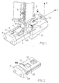
- the shears are composed as a whole of a chassis 1 having a U-shaped section open at the top.
- a vertical magazine 2 is fixed where the element to be cut is placed 3.
- the foot end piece is at the bottom, the head end piece (when it has not been previously separated) is at the top.
- blade carrier trolley 17 In the chassis, moves a guided drawer which is called blade carrier trolley 17 designated below by trolley; the carriage is guided to have a rectilinear and reciprocating movement with reduced friction.
- the store has a sidewall clamp 8 and two movable faces.
- FIG. 1 follows the description of the chassis. It consists of the assembly of longitudinal beams and spacers or partitions such as 5. The upper face is open. A removable cover 11 can partially close off this upper face. A jack 12 allows the cover 11 to be operated.
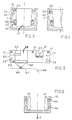
- the chassis includes two guide systems for the carriage, shown diagrammatically in FIG. 3.
- the rails 20 ensure the horizontality of the carriage stroke and the rails 26 ensure the parallelism of the stroke with the axis of the chassis.
- the solidly ribbed partition 5 forms the rear face of the chassis.
- the chassis ends at its lower part with a funnel 15.
- the chassis On each of the two lateral faces, inside, the chassis has a horizontal ramp 37 on its rear part and descending on its front part 38.
- This ramp cooperates with a pallet 34 as specified below.
- Figure 2 shows the carriage in perspective.
- FIG. 5 shows a longitudinal section of the carriage, which makes it possible to specify the function of the internal details of the cells.
- the foot end piece must fit exactly in height in the front socket 18.
- the depth of the front cell is greater than this dimension and, for each type of fuel, there is a shim 33 fixed by the screws to the bottom of the cell.
- a support 52 for blade 53 is fixed; it is embedded in the rear face and held by a system of screws (not shown).
- the blade 53 is fixed on its support so that the upper face of the blade is exactly in the cutting plane.
- the lower part of the rear cell is open, but the pallet 34 movable in rotation around the axis 35 can close this lower part; its role will be explained at the same time as the whole operation of the shears.
- the pallet has, on the right and on the left, two arms carrying a roller.
- This roller rolls on the ramp 37 of the chassis.
- the carriage comprises on the two lateral faces two sets of rollers (symmetrical with respect to the longitudinal plane). See Figures 3 and 4.
- FIG. 4 shows the high rails 29 fixed to the carriage and the high rollers 30 fixed to the chassis by the pin 31.
- rollers can be replaced by pads with the same result.
- the movement of the carriage in the chassis back and forth is ensured in a simple manner by one or two double-acting cylinders 60 with a horizontal axis.
- one solution consists in boring the body of said cylinders in the carriage, with the rod of each jack at the rear of the carriage, supported on the rear partition 5 of the chassis, by means of a ball joint (not shown).
- Figure 1 shows said store 2.
- the store comprises a lower part 13 and an upper part 43, the functions of which are different.
- the magazine is used to keep the fuel bundle in an upright position and to compress it laterally during cutting to prevent the pencils from twisting.
- a device forming part of the magazine lowers the fuel between each cut.
- the lower part of the magazine is composed of a rectangular prism 13 in which the fuel bundle slides with little play. It is therefore understood that the magazine is specific to a type of fuel.
- the rear face 8 of the lower part of the magazine is movable and serves as a sidewall.
- Figure 1 shows how this face 8 can be pushed by a jack to reduce the section at the bottom of the magazine.
- this mobile part has a different displacement for its upper edge and for its lower edge.
- the movable part 8 or rear face of the magazine is articulated at the top about an axis 9 which can move in a vertical slide 62.
- brackets 63 are articulated fixed on a slide 7 sliding in the grooves of the guides 6 (fixed to the frame).
- the jack 61 moves the slide 7 forward or backward.
- the upper edge of the movable part 8 remains in the vertical plane of the rear face of the magazine by means of two slides, while the lower edge remains parallel to the cutting plane and at constant distance.
- the front face of the lower part of the magazine carries a counter blade, the flat and horizontal lower part of which is in the cutting plane.
- FIG. 6 The right and left lateral faces of the lower part of the magazine are shown in FIG. 6.
- This wall 41 is movable parallel to itself thanks to a plurality of short-stroke cylinders 40 supported on a fixed vertical wall 13.
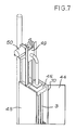
- the upper part of the magazine has a prismatic shape extending the section of the lower part.
- Figure 7 shows this upper part.
- the rear face 44 has the shape of a door opening thanks to the hinge 70. This facilitates the introduction of the fuel bundle.
- a pusher in the form of a horizontal plate 45 sliding in the magazine, set in motion by a vertical plate 49 (actuated by the motor 50), can apply a downward thrust to the beam fuel, when said motor 50 is supplied with energy.
- An interesting solution is to use a pneumatic motor supplied, at the desired time, with compressed air. It is also possible to use an electric motor equipped with a speed reducer.
- Example 1 Cutting a toe cap
- the carriage 17 is placed so that the front socket 18 for the foot end piece is under the magazine 2.
- a bundle of fuel is introduced into the store through the door 44, the foot end piece descending into the front cell 18 of the carriage.
- the wedge 33 placed at the bottom of the cell 18 was chosen so that the upper horizontal part of the foot end protrudes just at the cutting plane.
- the jack of the sidewall clamp 8 is actuated to hold the beam, then the carriage 17 is moved back by twenty or thirty millimeters. In this way, the base of the flank clamp attacks the skirt and separates the rear face of the skirt from the toe cap (by tearing off the welding points).
- the carriage 17 is then advanced until the front socket 18 drives the end piece under the counter blade, which completely separates the end of the rods from the beam.
- the skirt is completely separated from the foot end.
- a grapple grabs and lifts it, we back the carriage and we lower the tip through the funnel 15 in a barrel (canister).
- Example 2 cutting a beam
- the pallet 34 thanks to the ramp 37 of the chassis, is in the high position.
- the sidewall clamp 8 is loosened and the two side walls 41 of the lower part 13 of the magazine are moved aside by the jacks 40 with a short stroke (one centimeter is sufficient).
- the beam descends by itself until it touches the pallet 34.
- the pusher 45 is actuated at the same time which, if necessary, will serve to assist the descent.
- Pallet 34 has a double role: to prevent the beam from going too low and to adjust the cutting length. It follows that the pallet must be changed if we want to change the cutting length.
- the cylinders 40 of the lower side parts of the magazine 2 are actuated, then the cylinder 61 of the sidewall clamp 8 is actuated to compress all of the rods.
- the carriage is advanced: the blade 53 of the carriage in cooperation with the counter blade (on the front face of the magazine) cuts all the pencils to the chosen length.
Landscapes
- Physics & Mathematics (AREA)
- Engineering & Computer Science (AREA)
- Plasma & Fusion (AREA)
- General Engineering & Computer Science (AREA)
- High Energy & Nuclear Physics (AREA)
- Shearing Machines (AREA)
Claims (11)
- Vorrichtung zum Schneiden des mechanischen Aufbaus von Kernreaktorbrennelementkassetten, wobei der Aufbau mindestens ein unteres Endstück und Führungsrohre (3) aufweist, wobei der Aufbau senkrecht in einem Lager (2) angeordnet ist und das Schneiden durch die Bewegung einer Klinge (53) erfolgt, die auf einem Klingenträgerwagen (17) angeordnet ist, der sich in einem Gestell (1) geradlinig hin- und herbewegt,
dadurch gekennzeichnet,
daß der Klingenträgerwagen (17) in seinem oberen Teil zwei im wesentlichen rechteckige Kammern (18, 19) aufweist: eine vordere Kammer (18), die an ihrem unteren Teil geschlossen ist und dazu bestimmt ist, den unteren Teil der Führungsrohre aufzunehmen und zu schneiden, und eine hintere Kammer (19), die in ihrem unteren Teil offen ist und dazu bestimmt ist, die Rohre aufzunehmen und zu schneiden (3), wobei die hintere Kammer (19) zeitweise durch eine bewegliche Platte (34) verschließbar ist. - Vorrichtung nach Anspruch 1,
dadurch gekennzeichnet,
daß die Schnittebene horizontal ist und durch den oberen Teil der Klinge (53) bestimmt wird, die in der hinteren Kammer (19) angeordnet ist und durch den unteren Teil zweier Gegenklingen, wobei die vordere Gegenklinge am Gestell (1) und die hintere Gegenklinge am Lager (2) befestigt ist. - Vorrichtung nach einem der Ansprüche 1 oder 2,
dadurch gekennzeichnet,
daß der Klingenträgerwagen (17) durch zwei Spindeln mit horizontaler Achse bewegt wird, die zwischen einer Wandung (5) des Gehäuses (1) und dem Klingenträgerwagen (17) angeordnet sind. - Vorrichtung nach Anspruch 3,
dadurch gekennzeichnet,
daß der Körper einer jeden Spindel (16) in den Klingenträgerwagen (17) eingearbeitet ist und die Stange einer jeden Spindel (60) mit einer Gelenkkupplung an der Wand (5) des Gehäuses (1) befestigt ist. - Vorrichtung nach einem der Ansprüche 1 bis 4,
dadurch gekennzeichnet,
daß das Lager (2) einen unteren Teil (13) mit variablem Querschnitt und einen oberen offen Teil (43) mit konstantem rechtwinkligem Querschnitt aufweist. - Vorrichtung nach Anspruch 5,
dadurch gekennzeichnet,
daß die Hinterseite (8) des unteren Teils (13) eine schräge Stellung einnehmen kann, in der die Rohre, die in dem Lager angeordnet sind, komprimiert werden, durch die Einwirkung einer Spindel, die die hintere Seite über ein Kniegelenk verschiebt. - Vorrichtung nach einem der Ansprüche 5 oder 6,
dadurch gekennzeichnet,
daß sich die Seitenflächen (41) des unteren Teils (13) des Lagers (2) durch die Betätigung einer Mehrzahl von Spindeln um eine geringe Strecke bewegen können, wobei sie vertikal ausgerichtet bleiben. - Vorrichtung nach einem der vorstehenden Ansprüche,
dadurch gekennzeichnet,
daß die bewegliche Platte (34), die die hintere Kammer (19) zum Schneiden von Rohren abdecken kann, um eine Horizontalachse (35) drehbar angelenkt ist, die senkrecht zur Bewegungsrichtung des Wagens (17) verläuft, daß die Platte (34) auf jeder Seite durch einen unter der Platte angelenkten Arm gehalten wird und wobei die Platte mit einer Laufrolle (36) endet die auf einer auf dem Chassis (1) befestigten Rampe(37) rollt oder gleitet. - Vorrichtung nach Anspruch 8,
dadurch gekennzeichnet,
daß die Rampe an ihrem hinteren Teil (37) horizontal und an ihrem vorderen Teil (38) abfallend verläuft, wobei die Richtungsänderung so angeordnet ist, daß die Platte (34) auf dem Wege zum vorderen Teil des Wagens (17) die Schneidkammer (19) bis zur Beendigung eines Schneidvorgangs abschließt und anschließend kippt, um die abgeschnittenen Rohrteile in eine darunter angeordnete Tonne (15) fallenzulassen. - Vorrichtung nach einem der Ansprüche 1 bis 9,
dadurch gekennzeichnet,
daß der Klingenträgerwagen (17) mehrere Rollen (21) mit horizontaler Achse (22) aufweist, die auf horizontalen auf dem Chassis (1) befestigten Schienen (20) rollen. - Vorrichtung nach einem der Ansprüche 1 bis 9,
dadurch gekennzeichnet,
daß das Chassis (1) auf seinen beiden Seitenflächen mehrere Rollen (30) mit horizontaler Achse aufweist, die horizontal ausgerichtet sind und dadurch, daß der Wagen (17) auf jeder seiner Seitenflächen eine horizontale Schiene (29) aufweist und dadurch, daß die Schienen (29) auf den Rollen (30) angeordnet sind.
Applications Claiming Priority (2)
| Application Number | Priority Date | Filing Date | Title |
|---|---|---|---|
| FR8808029 | 1988-06-15 | ||
| FR8808029A FR2633088B1 (fr) | 1988-06-15 | 1988-06-15 | Dispositif pour cisailler un assemblage de tubes |
Publications (2)
| Publication Number | Publication Date |
|---|---|
| EP0347312A1 EP0347312A1 (de) | 1989-12-20 |
| EP0347312B1 true EP0347312B1 (de) | 1992-12-02 |
Family
ID=9367332
Family Applications (1)
| Application Number | Title | Priority Date | Filing Date |
|---|---|---|---|
| EP89401660A Expired - Lifetime EP0347312B1 (de) | 1988-06-15 | 1989-06-14 | Vorrichtung zum Schneiden eines Stabbündels |
Country Status (11)
| Country | Link |
|---|---|
| US (1) | US5054348A (de) |
| EP (1) | EP0347312B1 (de) |
| JP (1) | JPH0820553B2 (de) |
| KR (1) | KR0158198B1 (de) |
| CN (1) | CN1023268C (de) |
| CA (1) | CA1319766C (de) |
| CZ (1) | CZ280221B6 (de) |
| DE (1) | DE68903692T2 (de) |
| ES (1) | ES2037442T3 (de) |
| FR (1) | FR2633088B1 (de) |
| ZA (1) | ZA894491B (de) |
Cited By (1)
| Publication number | Priority date | Publication date | Assignee | Title |
|---|---|---|---|---|
| RU2109353C1 (ru) * | 1993-10-19 | 1998-04-20 | Компани Женераль де Матьер Нюклеэр | Способ разрезания на части элементов ядерной установки скалыванием и устройство для его осуществления |
Families Citing this family (13)
| Publication number | Priority date | Publication date | Assignee | Title |
|---|---|---|---|---|
| FR2741049B1 (fr) | 1995-11-15 | 1998-01-30 | Cogema | Conteneurs de conditionnement et de stockage, notamment de dechets dangereux manipules a distance ; procede pour leur remplissage |
| KR20030039943A (ko) * | 2001-11-16 | 2003-05-22 | 김철욱 | 김치와 전통장류를 이용한 기능성 발효돼지고기 및 그 제조방법 |
| FR2842291B1 (fr) * | 2002-07-11 | 2005-03-11 | Cogema | Procede de sechage de dechets metalliques a tendance pyrophorique, destines a etre compactes; etui de compactage et dispositif associes audit procede |
| KR20040024828A (ko) * | 2002-09-16 | 2004-03-22 | 백은기 | 편육(소고기,돼지고기)조리 방법 |
| KR20040032027A (ko) * | 2002-10-08 | 2004-04-14 | 백창용 | 돼지갈비의 선처리 방법 및 그 돼지갈비 |
| CN101562056B (zh) * | 2009-06-05 | 2011-09-14 | 中国原子能科学研究院 | 一种液下剪切装置 |
| BRMU9102974U8 (pt) * | 2011-12-26 | 2018-02-27 | Koda Filho Iasuo | aperfeiçoamento em inserto para chanfrar tubulações com quatro e oito arestas de corte e ainda com possibilidade de reafiação (recuperação) das arestas desgastadas, utilizando suporte com calços intercambiáveis |
| EP2812738B1 (de) | 2012-02-09 | 2016-10-12 | Dow Corning Corporation | Gradientenpolymerstrukturen und verfahren |
| CZ308622B6 (cs) * | 2015-10-09 | 2021-01-13 | ŠKODA JS a.s. | Zařízení na likvidaci čidel neutronového toku a/nebo termočlánků |
| CN110142447B (zh) * | 2019-06-27 | 2024-05-28 | 太仓金硕智控设备有限公司 | 一种钢格板自动化剪切装置及其剪切方法和制备方法 |
| CN113077916B (zh) * | 2021-06-07 | 2021-08-24 | 杭州景业智能科技股份有限公司 | 核燃料棒使用后的处理装置及处理方法 |
| KR102378781B1 (ko) * | 2021-07-16 | 2022-03-29 | 농업회사법인 드림푸드 주식회사 | 양념육 소스 조성물 및 그 제조방법 |
| CN115753399A (zh) * | 2022-12-30 | 2023-03-07 | 大连德昌线缆有限公司 | 汽车线耐切通性能测试机 |
Family Cites Families (10)
| Publication number | Priority date | Publication date | Assignee | Title |
|---|---|---|---|---|
| US2303880A (en) * | 1941-07-12 | 1942-12-01 | Lucy C Hilton | Dispensing device |
| US3855684A (en) * | 1968-03-25 | 1974-12-24 | Gen Electric | Nuclear fuel rod bundle handling means useful in an irradiated fuel reprocessing system |
| US3722338A (en) * | 1970-02-25 | 1973-03-27 | Saint Gobain Tech Nouvellas | Apparatus and process for the treatment of spent fuel |
| US3763770A (en) | 1970-12-15 | 1973-10-09 | Allied Chem | Method for shearing spent nuclear fuel bundles |
| US3777601A (en) * | 1971-03-29 | 1973-12-11 | P Strandell | Punching apparatus |
| FR2324093A1 (fr) * | 1975-09-11 | 1977-04-08 | Saint Gobain Techn Nouvelles | Procede et dispositif pour alimenter une tronconneuse de combustible nucleaire |
| FR2324094A1 (fr) * | 1975-09-11 | 1977-04-08 | Saint Gobain Techn Nouvelles | Procede et dispositif pour cisailler un faisceau de tubes contenant des combustibles nucleaires |
| FR2406868A1 (fr) * | 1977-10-20 | 1979-05-18 | British Nuclear Fuels Ltd | Machine a cisailler, notamment des elements combustibles nucleaires irradies |
| FR2502830A1 (fr) * | 1981-03-24 | 1982-10-01 | Sgn Soc Gen Tech Nouvelle | Dispositif rotatif permettant de cisailler un faisceau de tubes contenant des combustibles nucleaires |
| FR2527374A1 (fr) * | 1982-05-18 | 1983-11-25 | Commissariat Energie Atomique | Dispositif de cisaillage d'assemblages combustibles irradies |
-
1988
- 1988-06-15 FR FR8808029A patent/FR2633088B1/fr not_active Expired - Lifetime
-
1989
- 1989-06-13 ZA ZA894491A patent/ZA894491B/xx unknown
- 1989-06-14 ES ES198989401660T patent/ES2037442T3/es not_active Expired - Lifetime
- 1989-06-14 EP EP89401660A patent/EP0347312B1/de not_active Expired - Lifetime
- 1989-06-14 DE DE8989401660T patent/DE68903692T2/de not_active Expired - Fee Related
- 1989-06-14 KR KR1019890008256A patent/KR0158198B1/ko not_active Expired - Fee Related
- 1989-06-14 CZ CS893593A patent/CZ280221B6/cs unknown
- 1989-06-14 CA CA000602758A patent/CA1319766C/en not_active Expired - Fee Related
- 1989-06-15 US US07/366,671 patent/US5054348A/en not_active Expired - Fee Related
- 1989-06-15 JP JP1153567A patent/JPH0820553B2/ja not_active Expired - Lifetime
- 1989-06-15 CN CN89104980A patent/CN1023268C/zh not_active Expired - Fee Related
Cited By (1)
| Publication number | Priority date | Publication date | Assignee | Title |
|---|---|---|---|---|
| RU2109353C1 (ru) * | 1993-10-19 | 1998-04-20 | Компани Женераль де Матьер Нюклеэр | Способ разрезания на части элементов ядерной установки скалыванием и устройство для его осуществления |
Also Published As
| Publication number | Publication date |
|---|---|
| JPH0820553B2 (ja) | 1996-03-04 |
| CA1319766C (en) | 1993-06-29 |
| KR0158198B1 (ko) | 1998-12-15 |
| FR2633088A1 (fr) | 1989-12-22 |
| DE68903692T2 (de) | 1993-05-27 |
| CZ359389A3 (en) | 1995-06-14 |
| DE68903692D1 (de) | 1993-01-14 |
| FR2633088B1 (fr) | 1990-11-16 |
| JPH02161395A (ja) | 1990-06-21 |
| EP0347312A1 (de) | 1989-12-20 |
| US5054348A (en) | 1991-10-08 |
| ZA894491B (en) | 1990-03-28 |
| CN1040284A (zh) | 1990-03-07 |
| KR900000929A (ko) | 1990-01-31 |
| ES2037442T3 (es) | 1993-06-16 |
| CN1023268C (zh) | 1993-12-22 |
| CZ280221B6 (cs) | 1995-12-13 |
Similar Documents
| Publication | Publication Date | Title |
|---|---|---|
| EP0347312B1 (de) | Vorrichtung zum Schneiden eines Stabbündels | |
| FR2460027A1 (fr) | Procede de manutention des assemblages et crayons combustibles lors du rechargement d'un reacteur nucleaire | |
| WO2010066562A1 (fr) | Dispositif de distribution d'un produit dans une boîte de petri | |
| FR2465016A1 (fr) | Dispositif d'alimentation de fours a electrolyse | |
| FR2556489A1 (fr) | Appareil pour abattre des barres de poison combustible afin de les stocker dans un volume reduit | |
| EP0244278B1 (de) | Verfahren zum Einsetzen eines Stabbündels eines Kernbrennstoffbündels in einen Behälter und Anlage zur Durchführung dieses Verfahrens | |
| WO1983004454A1 (fr) | Procede, installation et dispositif pour le compactage d'objets oblongs | |
| EP0344051B1 (de) | Kernbrennelementaufnahme- und Zerlegungszelle | |
| EP0218494A1 (de) | Verfahren und Vorrichtung zur Kompaktierung eines Brennstabbündels | |
| FR2574252A1 (fr) | Installation pour la fabrication automatisee de brochettes | |
| FR2611077A1 (fr) | Procede et dispositif pour couper des elements combustibles irradies en position horizontale a l'aide d'un chariot porte-lame | |
| FR2552581A1 (fr) | Systeme de transfert d'assemblages combustibles nucleaires | |
| FR2927284A1 (fr) | Benne de transport de materiau divers a bouclier ejecteur. | |
| WO1994016449A1 (fr) | Procede et dispositif de compactage, particulierement adaptes au compactage de matieres dangereuses | |
| CA2938716A1 (fr) | Systeme pour la realisation d'operations liees a l'exploitation de cellules d'une installation de production d'aluminium par electrolyse | |
| FR2577865A1 (fr) | Dispositif de relevage de la charpente supportant la couverture d'un vehicule de transport | |
| CA1162513A (fr) | Appareil d'electrolyse | |
| BE1011646A3 (fr) | Appareils et procede de protection et de transport d'ensembles combustibles nucleaires. | |
| FR2564020A1 (fr) | Dispositif de mise en place de ressorts en epingle a cheveux sur des plaquettes, notamment pour grilles d'assemblage de combustible | |
| FR2627891A1 (fr) | Poussoir pour magasin d'elements combustibles irradies | |
| BE1014877A3 (fr) | Procede et dispositif d'elimination, sous forme compacte, | |
| EP0493259A1 (de) | Verfahren und Vorrichtung zur Reparatur eines Abstandhalters in einem Kernreaktorbrennstabbündel | |
| EP0108673B1 (de) | Verfahren und Gerät zum Einsetzen von haarnadelförmigen Federn auf Platten, insbesondere für Roste einer Brennstoffanordnung | |
| FR2534732A1 (fr) | Procede et dispositif pour le demantelement de grappes de barres irradiees | |
| FR2848329A1 (fr) | Dispositif de decoupage et de prelevement d'une portion d'une grille-entretoise d'un assemblage de combustible. |
Legal Events
| Date | Code | Title | Description |
|---|---|---|---|
| PUAI | Public reference made under article 153(3) epc to a published international application that has entered the european phase |
Free format text: ORIGINAL CODE: 0009012 |
|
| AK | Designated contracting states |
Kind code of ref document: A1 Designated state(s): BE CH DE ES GB IT LI NL SE |
|
| 17P | Request for examination filed |
Effective date: 19900130 |
|
| 17Q | First examination report despatched |
Effective date: 19920325 |
|
| GRAA | (expected) grant |
Free format text: ORIGINAL CODE: 0009210 |
|
| RIN1 | Information on inventor provided before grant (corrected) |
Inventor name: CHAUVIRE, PASCAL Inventor name: TUCOULAT, DANIEL Inventor name: GUILLOTEAU, RENE Inventor name: ANCIAUX, GHISLAIN |
|
| AK | Designated contracting states |
Kind code of ref document: B1 Designated state(s): BE CH DE ES GB IT LI NL SE |
|
| ITF | It: translation for a ep patent filed | ||
| GBT | Gb: translation of ep patent filed (gb section 77(6)(a)/1977) |
Effective date: 19921201 |
|
| REF | Corresponds to: |
Ref document number: 68903692 Country of ref document: DE Date of ref document: 19930114 |
|
| REG | Reference to a national code |
Ref country code: ES Ref legal event code: FG2A Ref document number: 2037442 Country of ref document: ES Kind code of ref document: T3 |
|
| PLBE | No opposition filed within time limit |
Free format text: ORIGINAL CODE: 0009261 |
|
| STAA | Information on the status of an ep patent application or granted ep patent |
Free format text: STATUS: NO OPPOSITION FILED WITHIN TIME LIMIT |
|
| 26N | No opposition filed | ||
| EAL | Se: european patent in force in sweden |
Ref document number: 89401660.9 |
|
| PGFP | Annual fee paid to national office [announced via postgrant information from national office to epo] |
Ref country code: NL Payment date: 19950523 Year of fee payment: 7 |
|
| PGFP | Annual fee paid to national office [announced via postgrant information from national office to epo] |
Ref country code: GB Payment date: 19950606 Year of fee payment: 7 |
|
| PGFP | Annual fee paid to national office [announced via postgrant information from national office to epo] |
Ref country code: SE Payment date: 19950621 Year of fee payment: 7 |
|
| PG25 | Lapsed in a contracting state [announced via postgrant information from national office to epo] |
Ref country code: GB Effective date: 19960614 |
|
| PG25 | Lapsed in a contracting state [announced via postgrant information from national office to epo] |
Ref country code: SE Effective date: 19960615 |
|
| PG25 | Lapsed in a contracting state [announced via postgrant information from national office to epo] |
Ref country code: NL Effective date: 19970101 |
|
| GBPC | Gb: european patent ceased through non-payment of renewal fee |
Effective date: 19960614 |
|
| EUG | Se: european patent has lapsed |
Ref document number: 89401660.9 |
|
| NLV4 | Nl: lapsed or anulled due to non-payment of the annual fee |
Effective date: 19970101 |
|
| PGFP | Annual fee paid to national office [announced via postgrant information from national office to epo] |
Ref country code: DE Payment date: 20000617 Year of fee payment: 12 |
|
| PGFP | Annual fee paid to national office [announced via postgrant information from national office to epo] |
Ref country code: ES Payment date: 20000620 Year of fee payment: 12 |
|
| PGFP | Annual fee paid to national office [announced via postgrant information from national office to epo] |
Ref country code: CH Payment date: 20000623 Year of fee payment: 12 |
|
| PGFP | Annual fee paid to national office [announced via postgrant information from national office to epo] |
Ref country code: BE Payment date: 20000711 Year of fee payment: 12 |
|
| PG25 | Lapsed in a contracting state [announced via postgrant information from national office to epo] |
Ref country code: ES Free format text: LAPSE BECAUSE OF NON-PAYMENT OF DUE FEES Effective date: 20010615 |
|
| PG25 | Lapsed in a contracting state [announced via postgrant information from national office to epo] |
Ref country code: LI Free format text: LAPSE BECAUSE OF NON-PAYMENT OF DUE FEES Effective date: 20010630 Ref country code: CH Free format text: LAPSE BECAUSE OF NON-PAYMENT OF DUE FEES Effective date: 20010630 Ref country code: BE Free format text: LAPSE BECAUSE OF NON-PAYMENT OF DUE FEES Effective date: 20010630 |
|
| BERE | Be: lapsed |
Owner name: SOC. GENERALE POUR LES TECHNIQUES NOUVELLES SGN Effective date: 20010630 |
|
| REG | Reference to a national code |
Ref country code: CH Ref legal event code: PL |
|
| PG25 | Lapsed in a contracting state [announced via postgrant information from national office to epo] |
Ref country code: DE Free format text: LAPSE BECAUSE OF NON-PAYMENT OF DUE FEES Effective date: 20020403 |
|
| REG | Reference to a national code |
Ref country code: ES Ref legal event code: FD2A Effective date: 20030203 |
|
| PG25 | Lapsed in a contracting state [announced via postgrant information from national office to epo] |
Ref country code: IT Free format text: LAPSE BECAUSE OF NON-PAYMENT OF DUE FEES Effective date: 20050614 |