EP0108673B1 - Verfahren und Gerät zum Einsetzen von haarnadelförmigen Federn auf Platten, insbesondere für Roste einer Brennstoffanordnung - Google Patents
Verfahren und Gerät zum Einsetzen von haarnadelförmigen Federn auf Platten, insbesondere für Roste einer Brennstoffanordnung Download PDFInfo
- Publication number
- EP0108673B1 EP0108673B1 EP83402055A EP83402055A EP0108673B1 EP 0108673 B1 EP0108673 B1 EP 0108673B1 EP 83402055 A EP83402055 A EP 83402055A EP 83402055 A EP83402055 A EP 83402055A EP 0108673 B1 EP0108673 B1 EP 0108673B1
- Authority
- EP
- European Patent Office
- Prior art keywords
- plate
- spring
- springs
- legs
- corridor
- Prior art date
- Legal status (The legal status is an assumption and is not a legal conclusion. Google has not performed a legal analysis and makes no representation as to the accuracy of the status listed.)
- Expired
Links
- 238000000034 method Methods 0.000 title claims description 6
- 238000003780 insertion Methods 0.000 claims description 15
- 230000037431 insertion Effects 0.000 claims description 15
- 238000003466 welding Methods 0.000 claims description 15
- 235000012431 wafers Nutrition 0.000 description 10
- 239000012634 fragment Substances 0.000 description 6
- 239000000446 fuel Substances 0.000 description 6
- 238000009434 installation Methods 0.000 description 6
- 238000006073 displacement reaction Methods 0.000 description 3
- 230000005484 gravity Effects 0.000 description 2
- XEEYBQQBJWHFJM-UHFFFAOYSA-N iron Substances [Fe] XEEYBQQBJWHFJM-UHFFFAOYSA-N 0.000 description 2
- 229910052742 iron Inorganic materials 0.000 description 2
- QCWXUUIWCKQGHC-UHFFFAOYSA-N Zirconium Chemical compound [Zr] QCWXUUIWCKQGHC-UHFFFAOYSA-N 0.000 description 1
- 229910001093 Zr alloy Inorganic materials 0.000 description 1
- 229910045601 alloy Inorganic materials 0.000 description 1
- 239000000956 alloy Substances 0.000 description 1
- 230000000712 assembly Effects 0.000 description 1
- 238000000429 assembly Methods 0.000 description 1
- 230000006835 compression Effects 0.000 description 1
- 238000007906 compression Methods 0.000 description 1
- 238000011109 contamination Methods 0.000 description 1
- 238000010586 diagram Methods 0.000 description 1
- 238000000605 extraction Methods 0.000 description 1
- 239000000463 material Substances 0.000 description 1
- 239000008188 pellet Substances 0.000 description 1
- 239000000523 sample Substances 0.000 description 1
- 125000006850 spacer group Chemical group 0.000 description 1
- 230000001502 supplementing effect Effects 0.000 description 1
- 229910052726 zirconium Inorganic materials 0.000 description 1
Images

Classifications
-
- B—PERFORMING OPERATIONS; TRANSPORTING
- B23—MACHINE TOOLS; METAL-WORKING NOT OTHERWISE PROVIDED FOR
- B23P—METAL-WORKING NOT OTHERWISE PROVIDED FOR; COMBINED OPERATIONS; UNIVERSAL MACHINE TOOLS
- B23P19/00—Machines for simply fitting together or separating metal parts or objects, or metal and non-metal parts, whether or not involving some deformation; Tools or devices therefor so far as not provided for in other classes
- B23P19/04—Machines for simply fitting together or separating metal parts or objects, or metal and non-metal parts, whether or not involving some deformation; Tools or devices therefor so far as not provided for in other classes for assembling or disassembling parts
-
- Y—GENERAL TAGGING OF NEW TECHNOLOGICAL DEVELOPMENTS; GENERAL TAGGING OF CROSS-SECTIONAL TECHNOLOGIES SPANNING OVER SEVERAL SECTIONS OF THE IPC; TECHNICAL SUBJECTS COVERED BY FORMER USPC CROSS-REFERENCE ART COLLECTIONS [XRACs] AND DIGESTS
- Y10—TECHNICAL SUBJECTS COVERED BY FORMER USPC
- Y10T—TECHNICAL SUBJECTS COVERED BY FORMER US CLASSIFICATION
- Y10T29/00—Metal working
- Y10T29/49—Method of mechanical manufacture
- Y10T29/49826—Assembling or joining
- Y10T29/49908—Joining by deforming
- Y10T29/49924—Joining by deforming of parallel side-by-side elongated members
-
- Y—GENERAL TAGGING OF NEW TECHNOLOGICAL DEVELOPMENTS; GENERAL TAGGING OF CROSS-SECTIONAL TECHNOLOGIES SPANNING OVER SEVERAL SECTIONS OF THE IPC; TECHNICAL SUBJECTS COVERED BY FORMER USPC CROSS-REFERENCE ART COLLECTIONS [XRACs] AND DIGESTS
- Y10—TECHNICAL SUBJECTS COVERED BY FORMER USPC
- Y10T—TECHNICAL SUBJECTS COVERED BY FORMER US CLASSIFICATION
- Y10T29/00—Metal working
- Y10T29/49—Method of mechanical manufacture
- Y10T29/49826—Assembling or joining
- Y10T29/49908—Joining by deforming
- Y10T29/49936—Surface interlocking
-
- Y—GENERAL TAGGING OF NEW TECHNOLOGICAL DEVELOPMENTS; GENERAL TAGGING OF CROSS-SECTIONAL TECHNOLOGIES SPANNING OVER SEVERAL SECTIONS OF THE IPC; TECHNICAL SUBJECTS COVERED BY FORMER USPC CROSS-REFERENCE ART COLLECTIONS [XRACs] AND DIGESTS
- Y10—TECHNICAL SUBJECTS COVERED BY FORMER USPC
- Y10T—TECHNICAL SUBJECTS COVERED BY FORMER US CLASSIFICATION
- Y10T29/00—Metal working
- Y10T29/53—Means to assemble or disassemble
- Y10T29/53478—Means to assemble or disassemble with magazine supply
Definitions
- the present invention relates to the installation of hairpin springs intended to support the fuel rods in spacer grids for fuel assembly.
- Very frequently used fuel assemblies include a bundle of fuel rods (each constituted by a stack of pellets in a sealed sheath) held in a structure.
- the latter comprises grids distributed along the assembly and constituted by plates arranged in two orthogonal directions, to define cells the major part of which at least is crossed by pencils.
- Each of these cells is provided with means based on the pencil which crosses the cell to support it.
- the springs generally have a hairpin shape, with two branches.
- it is necessary to provide in the same grid several types of spring because the grid has edges and that often some cells are occupied by elements other than rods, for example by guide tubes.
- One type will frequently have two identical branches, while another type will have different branches.
- These springs are first inserted, then definitively secured to the plates by welding the two branches one on the other at well-defined points, between which there are windows formed in the grid plate.
- each spring is a delicate operation: it is necessary to locate them precisely so as not to pinch them on the plates during the welding operation, and to avoid any contamination.
- the mounting of the springs and their welding have been carried out manually, which constitutes a long and painful operation, moreover liable to give rise to errors when springs of different types must be placed in well-defined zones. of the brochure.
- the present invention aims to provide a method and a device for placing springs which meet better than those previously known the requirements of practice, in particular in that they allow rapid and safe installation.
- the invention proposes in particular a method of inserting hairpin springs with two branches straddling a plate provided with windows making it possible to locally weld the branches to one another, characterized in that the plate is kept in a determined position, in that the spring is displaced in an orientation close to the plane of the plate towards its insertion location, perpendicular to the length of the plate, after having covered at least the window of the plate furthest from the zone through which the spring is introduced using masks which can be moved parallel to the plane of the plate in order to avoid inadvertent engagement of one end of a branch of the spring in the window and in that the operation is repeated after displacement of the plate in the direction of the length of one or more determined steps.
- the sequence of installation of the springs incorporates the electrical welding of the two branches of a spring one against the other immediately after installation of this spring and before displacement of the plate for the establishment of the next spring. This gives us the certainty that no untimely movement of the spring could have occurred between the insertion operation and the welding operation.
- the invention also provides a device for inserting hairpin springs with two branches straddling a plate provided with windows making it possible to locally weld the branches one against the other, characterized in that it comprises means to receive one insert at a time and move it lengthwise; a guide corridor for each spring in turn, associated with means for moving the spring along the corridor towards its insertion location, cooperating to keep the spring in an orientation close to the plane of the plate during its movement, and masks movable parallel to the plane of the plate from the edge thereof remote from the zone through which the introduction takes place, making it possible to cover, on both sides of the plate, the window furthest from the zone by which the introduction is carried out in order to avoid inadvertent engagement of one end of a branch of the spring in this window.
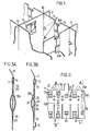
- This grid 10 is constituted by plates 11, generally in zirconium-based alloy called "Zircaloy”, assembled half-iron and welded at their connection points 12.
- Each of the plates 11 has bosses 13 for supporting fuel rods (not shown) and various openings cooperating with the springs intended to apply the rods to the bosses.
- Figure 1 appear only double springs 15A which are inserted in the notches 14 of the plates opening onto one of the edges.
- each of the springs 1 5A can be put in place by sliding its branches on either side of the plate 11 until the upper loop of the spring comes into contact with the plate, at the bottom of the notch 14.
- Windows 19 made in the plate make it possible to fix the two spring branches directly to each other using a welding point 20.
- the simple spring 15B shown in FIG. 3B has an asymmetrical constitution. Its branch 22 is similar to the branches of the spring 15A.
- the other branch 23 is designed so as to constitute a ball joint delimited by two folds 24 capable of coming into contact with the branch 22 through openings 25 in the wafer, in order to avoid transmitting the compressive forces therein.
- the two branches of the spring 15B are welded to each other through windows 19 on the finished grid. But the loop does not come to be placed at the bottom of a notch, but in an extension of the upper opening 19, formed by one of the bosses 13. It is therefore not possible to pass the branches 22 and 23 directly and on the other side of the brochure.
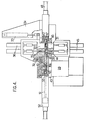
- the device shown in Figure 4, the fraction of which ensures precise positioning and welding of the spring is shown in Figure 5, is intended for mounting the springs 1 5A.
- This device comprises a frame 29 of which is fixed a fixed lower jaw 31.
- a movable upper jaw 30 is mounted so as to be able to rotate on an axis 32 secured to the jaws 30 and 31.
- An actuating cylinder 33 for example pneumatic, is mounted between a console 34 secured to the fixed lower jaw 31 and the movable upper jaw 30.
- This jack makes it possible to tilt the jaw 30 between the working position in which it is shown in FIGS. 4 and 5 and a position where it releases the position of positioning and welding of the spring, thus making it possible to install or remove a plate 11.
- the lower jaw 31 comprises means for receiving a plate at a time and moving it in the direction of its length, that is to say transversely to the plane of FIGS. 4 and 5.
- these means comprise a slide 39 comprising profiled jaws 41.
- the plate is fixed by means (not shown) located at the ends of the lower jaw.
- the jaws further comprise a spring stop 42, the role of which will appear later.
- the slide is carried by a slide 43 linked to the frame at its two ends by means not shown.
- the frame also carries means for advancing the slide by equals to the interval which separates two successive bands of the plate 11.
- a corridor 49 for guiding each spring in turn, associated with means for moving the spring along from the corridor to the plate.
- this corridor is formed in a part integral with the frame and extends between the positioning and welding station and a chamber for receiving a charger 50 in which the springs 15A are stacked, transverse to the plane of the figure.
- the charger 50 has an internal profile which follows the shape of the springs and it contains a compression spring (not shown) which pushes the stack of springs after each extraction of a spring so as to bring another one opposite the guide passage 49.
- the supply of springs is carried out by virtue of a strip arrangement of the springs, linked together by tenons which are sheared during introduction into the guide passage 49.
- the means for moving the spring include a double-acting cylinder 52, for example pneumatic, the piston of which is extended by a rod 51 terminated by a notch 53 intended to come to bear against the upper loop of the spring 15A to be inserted.
- the actuator 52 is implemented from the rest position shown in FIG. 4, the rod 51 pushes the spring until its branches come to bear against the stop 42.
- the device shown in Figure 4 is intended not only to position the springs, but also to weld them in place.
- the jaws 30 and 31 each carry a set of electrodes.
- the upper jaw 30 comprises two electrodes 35 each actuable by a jack, for example pneumatic 36, making it possible to move them between the rest position where they are illustrated in FIG. 4 and a working position where the electrodes rest on the spring, facing the windows 19 of the wafer.
- the lower jaw 31 is provided with two electrodes 44 actuated by jacks 45. When the two sets of jacks are actuated, the two opposite branches of the spring 15A placed opposite are applied one against the other through windows 19.
- the device shown in FIG. 4 comprises movable masks 47, intended to cover the window 19 during the introduction of the spring 15A.
- These masks 47 consist of two thin sheets displaceable by a jack 48, for example pneumatic, between the retracted position where they are shown in FIG. 4 and the advanced position where they are shown in FIG. 5 and where they cover the window 19 and are end at mid-length of the plate.
- the spacing of these sheets is fixed by a shim (not shown) to a value slightly greater than the thickness of the plate.
- the device is obviously supplemented by means for supplying current to the welding electrodes and by a mechanism for sequentially controlling the various elements, which will generally be constituted by a programmable automaton, although manual control by operator is obviously possible.
- a device for vibrating the slide 39 can be provided in order to facilitate the positioning of the spring. In all cases, the operation will be as follows during the fitting of a wafer.
- the upper jaw 30 being raised, a bare plate 11 is put in place while the slide occupies the position for which the first strip of the plate 11 faces the corridor 49.
- the upper jaw is closed, the electrodes of the two jaws being in the position shown in Figures 4 and 5.
- the jaws carrying the plate are then trapped and can no longer move only transversely to the plane of the figure. If the first strip is to receive a spring 1 5A, the jack 48 is first actuated to bring the masks 47 into the position shown in FIG. 5, then the jack 52 is actuated to bring the rod 41 from the position shown in FIG. 4 at the position shown in Figure 5 and insert a spring 15A.
- the jacks 36 and 45 are actuated to apply the electrodes 35 and 44 against the branches of the spring and hold them in position on the plate.
- the rod 51 and the masks 47 are retracted by actuation of the jacks 52 and 48, the withdrawal of the masks being accompanied by the coming into contact of the two branches of the spring 1 5A through the windows 19, under the action of the electrodes .
- Welding is then carried out, then the electrodes 35 and 44 are retracted.
- the transverse displacement means of the slide 39 are actuated to move the wafer either by one step or by several steps, depending on whether the next location of the wafer is or is not equipped with a double spring, then the sequence is repeated. Once the plate is fully equipped, the upper jaw 30 is opened to allow the plate to be removed and replaced by a bare plate.
- the device is advantageously placed so that the gravity forces acting on the spring to be inserted promote its insertion.
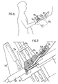
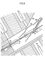
- the device of FIGS. 6 to 8 has a general constitution which is similar to that already described with reference to FIGS. 4 and 5 and the corresponding elements will be designated by the same number assigned with the index 1. It also includes a frame 29 1 on which is fixed a lower jaw 31 1 , carrying an axis 32 1 around which a jack 33 1 makes it possible to tilt an upper jaw 30 1 . But the frame is placed so that the wafer to be fitted 11 is maintained not horizontally, but with an angle a which will generally be of the order of 30 °. In addition, the corridor 49 1 is given an inclination relative to the plane of the plate, generally of the order of 20 °, and it is placed so as to guide the non-active branch of the spring 15B towards the insertion window 19.
- the corridor has a total inclination on the horizontal of the order of approximately 50 ° which allows the spring to slide by gravity along the plate 11 after the action of the introduction rod 511 has stopped (FIG. 7).
- masks 47 i and the role of the upper mask is particularly important here because of the increased risk of attachment of the upper branch of the spring 15B in the window or the most distant windows of the introduction area.
- FIGS. 6 to 8 The operation of the device in FIGS. 6 to 8 is very similar to that of the device in FIGS. 4 and 5: the plates to be fitted, possibly already provided with their double spring, are still placed in a slide displaceable by means not shown.
- the devices which have just been described can be integrated into a working assembly also comprising a supply device constituted by a set of storage drawers placed next to the frame of each device and having drawers receiving, on one side, bare plates (or already equipped with a type of spring) and full spring chargers and, on the other, drawers for storing equipped plates before evacuation.
- the programmable sequential controller can be entirely conventional in nature. It will generally be provided to carry out all the required control operations, possibly by supplementing the device with probes not shown.
Landscapes
- Engineering & Computer Science (AREA)
- Mechanical Engineering (AREA)
- Butt Welding And Welding Of Specific Article (AREA)
- Container, Conveyance, Adherence, Positioning, Of Wafer (AREA)
- Manipulator (AREA)
Claims (12)
Applications Claiming Priority (2)
| Application Number | Priority Date | Filing Date | Title |
|---|---|---|---|
| FR8217717A FR2535101A1 (fr) | 1982-10-22 | 1982-10-22 | Procede et dispositif de mise en place de ressorts en epingle a cheveux sur des plaquettes, notamment pour grilles d'assemblage de combustible |
| FR8217717 | 1982-10-22 |
Publications (2)
| Publication Number | Publication Date |
|---|---|
| EP0108673A1 EP0108673A1 (de) | 1984-05-16 |
| EP0108673B1 true EP0108673B1 (de) | 1986-06-04 |
Family
ID=9278510
Family Applications (1)
| Application Number | Title | Priority Date | Filing Date |
|---|---|---|---|
| EP83402055A Expired EP0108673B1 (de) | 1982-10-22 | 1983-10-21 | Verfahren und Gerät zum Einsetzen von haarnadelförmigen Federn auf Platten, insbesondere für Roste einer Brennstoffanordnung |
Country Status (4)
| Country | Link |
|---|---|
| US (1) | US4633569A (de) |
| EP (1) | EP0108673B1 (de) |
| DE (1) | DE3363951D1 (de) |
| FR (1) | FR2535101A1 (de) |
Families Citing this family (2)
| Publication number | Priority date | Publication date | Assignee | Title |
|---|---|---|---|---|
| FR2564020B1 (fr) * | 1984-05-10 | 1986-10-24 | Cogema Framatome Uranium Pechi | Dispositif de mise en place de ressorts en epingle a cheveux sur des plaquettes, notamment pour grilles d'assemblage de combustible |
| CN114603345B (zh) * | 2022-03-29 | 2024-10-25 | 南京中拓科技有限公司 | 一种基于弹簧的装配装置的装配方法 |
Family Cites Families (5)
| Publication number | Priority date | Publication date | Assignee | Title |
|---|---|---|---|---|
| US2629296A (en) * | 1948-02-10 | 1953-02-24 | Solo Products Corp | Machine for automatically carding curlers |
| US2629236A (en) * | 1949-05-19 | 1953-02-24 | Sunkist Growers Inc | Refrigerated beverage dispenser |
| US4261098A (en) * | 1979-05-29 | 1981-04-14 | Lincoln Walter B | Apparatus for clipping sheets together |
| FR2459759A1 (fr) * | 1979-06-26 | 1981-01-16 | Petit Bernard | Appareil a encarter automatiquement les pinces a linge, du type pinces avec ressorts |
| FR2474229B1 (fr) * | 1980-01-22 | 1986-08-22 | Commissariat Energie Atomique | Grille entretoise pour assemblage combustible de reacteur nucleaire |
-
1982
- 1982-10-22 FR FR8217717A patent/FR2535101A1/fr active Granted
-
1983
- 1983-10-21 EP EP83402055A patent/EP0108673B1/de not_active Expired
- 1983-10-21 DE DE8383402055T patent/DE3363951D1/de not_active Expired
- 1983-10-24 US US06/545,012 patent/US4633569A/en not_active Expired - Fee Related
Also Published As
| Publication number | Publication date |
|---|---|
| FR2535101A1 (fr) | 1984-04-27 |
| EP0108673A1 (de) | 1984-05-16 |
| DE3363951D1 (en) | 1986-07-10 |
| FR2535101B1 (de) | 1985-03-08 |
| US4633569A (en) | 1987-01-06 |
Similar Documents
| Publication | Publication Date | Title |
|---|---|---|
| FR3029127B1 (fr) | Dispositif de chargement d'un outil de soudage de grille d'espacement | |
| FR2828428A1 (fr) | Dispositif de decollement de substrats et procede associe | |
| FR2561151A1 (fr) | Procede et installation de soudage de grilles pour assemblage de combustible nucleaire | |
| WO2008135359A1 (fr) | Conteneur pour le transport et/ou stockage de matieres nucleaires, le conteneur comprenant une structure mobile de conduction thermique | |
| EP0123607B1 (de) | Niederhaltungsvorrichtung für Kernreaktor | |
| EP0108673B1 (de) | Verfahren und Gerät zum Einsetzen von haarnadelförmigen Federn auf Platten, insbesondere für Roste einer Brennstoffanordnung | |
| EP0218494B1 (de) | Verfahren und Vorrichtung zur Kompaktierung eines Brennstabbündels | |
| FR3101485A3 (fr) | Appareil et procédé d’assemblage d’empilement de piles à combustibles | |
| FR2690554A1 (fr) | Dispositif et procédé de montage de crayons dans un squelette d'assemblage combustible nucléaire. | |
| WO2020002463A1 (fr) | Dispositif d'intervention sur un assemblage de combustible nucléaire | |
| EP0163568B1 (de) | Gerät zum Einsetzen von haarnadelförmigen Federn auf Platten, insbesondere für Roste einer Brennstoffanordnung | |
| EP0244278B1 (de) | Verfahren zum Einsetzen eines Stabbündels eines Kernbrennstoffbündels in einen Behälter und Anlage zur Durchführung dieses Verfahrens | |
| EP2589474A1 (de) | Automatisiertes Verfahren zum Einfügen von Isolierkörpern in die Hohlräume von Blockbausteinen, und Produktionslinie zum automatischen Einfügen für die Umsetzung dieses Verfahrens | |
| WO2001045114A1 (fr) | Dispositif et procede de montage d'une grille-entretoise d'un assemblage de combustible pour un reacteur nucleaire | |
| EP0435774B1 (de) | Vorrichtung zum Laden und Entladen einer Speicherkassette mit flachen Gegenständen | |
| FR2513796A1 (fr) | Aiguille combustible et fertile pour reacteur nucleaire et son procede de fabrication | |
| EP0344051A1 (de) | Kernbrennelementaufnahme- und Zerlegungszelle | |
| CH625724A5 (de) | ||
| EP0156686B2 (de) | Halterungsanordnung für Kernbrennstoffbündel in einem Kernreaktor | |
| EP0384825B1 (de) | Abstandshalter für Kernbrennstabbündel und Verfahren zur Montage unter Anwendung des Abstandshalters | |
| FR2683080A1 (fr) | Procede destine a assembler un assemblage de combustible nucleaire et appareil a cet effet. | |
| FR2721445A1 (fr) | Machine de fabrication de faisceaux électriques comportant des connecteurs simples et son utilisation. | |
| EP0493259B1 (de) | Verfahren und Vorrichtung zur Reparatur eines Abstandhalters in einem Kernreaktorbrennstabbündel | |
| FR2579359A1 (fr) | Procede et dispositif de cartographie d'assemblage de combustible nucleaire | |
| EP4156206A1 (de) | Zerlegungssystem für kerntechnische anlage |
Legal Events
| Date | Code | Title | Description |
|---|---|---|---|
| PUAI | Public reference made under article 153(3) epc to a published international application that has entered the european phase |
Free format text: ORIGINAL CODE: 0009012 |
|
| AK | Designated contracting states |
Designated state(s): BE DE SE |
|
| 17P | Request for examination filed |
Effective date: 19840808 |
|
| RAP1 | Party data changed (applicant data changed or rights of an application transferred) |
Owner name: SOCIETE COGEMA, FRAMATOME ET URANIUM PECHINEY |
|
| GRAA | (expected) grant |
Free format text: ORIGINAL CODE: 0009210 |
|
| AK | Designated contracting states |
Kind code of ref document: B1 Designated state(s): BE DE SE |
|
| REF | Corresponds to: |
Ref document number: 3363951 Country of ref document: DE Date of ref document: 19860710 |
|
| PLBE | No opposition filed within time limit |
Free format text: ORIGINAL CODE: 0009261 |
|
| STAA | Information on the status of an ep patent application or granted ep patent |
Free format text: STATUS: NO OPPOSITION FILED WITHIN TIME LIMIT |
|
| 26N | No opposition filed | ||
| PGFP | Annual fee paid to national office [announced via postgrant information from national office to epo] |
Ref country code: BE Payment date: 19931027 Year of fee payment: 11 |
|
| PGFP | Annual fee paid to national office [announced via postgrant information from national office to epo] |
Ref country code: DE Payment date: 19931228 Year of fee payment: 11 |
|
| PG25 | Lapsed in a contracting state [announced via postgrant information from national office to epo] |
Ref country code: BE Effective date: 19941031 |
|
| EAL | Se: european patent in force in sweden |
Ref document number: 83402055.4 |
|
| BERE | Be: lapsed |
Owner name: SOC. COGEMA FRAMATOME ET URANIUM PECHINEY Effective date: 19941031 |
|
| PG25 | Lapsed in a contracting state [announced via postgrant information from national office to epo] |
Ref country code: DE Effective date: 19950701 |
|
| PGFP | Annual fee paid to national office [announced via postgrant information from national office to epo] |
Ref country code: SE Payment date: 19961017 Year of fee payment: 14 |
|
| PG25 | Lapsed in a contracting state [announced via postgrant information from national office to epo] |
Ref country code: SE Free format text: LAPSE BECAUSE OF NON-PAYMENT OF DUE FEES Effective date: 19971022 |
|
| EUG | Se: european patent has lapsed |
Ref document number: 83402055.4 |