EP0108673B1 - Process and apparatus for placing hair-pin-shaped springs on plates, particularly for grids for combustibles - Google Patents
Process and apparatus for placing hair-pin-shaped springs on plates, particularly for grids for combustibles Download PDFInfo
- Publication number
- EP0108673B1 EP0108673B1 EP83402055A EP83402055A EP0108673B1 EP 0108673 B1 EP0108673 B1 EP 0108673B1 EP 83402055 A EP83402055 A EP 83402055A EP 83402055 A EP83402055 A EP 83402055A EP 0108673 B1 EP0108673 B1 EP 0108673B1
- Authority
- EP
- European Patent Office
- Prior art keywords
- plate
- spring
- springs
- legs
- corridor
- Prior art date
- Legal status (The legal status is an assumption and is not a legal conclusion. Google has not performed a legal analysis and makes no representation as to the accuracy of the status listed.)
- Expired
Links
Images

Classifications
-
- B—PERFORMING OPERATIONS; TRANSPORTING
- B23—MACHINE TOOLS; METAL-WORKING NOT OTHERWISE PROVIDED FOR
- B23P—METAL-WORKING NOT OTHERWISE PROVIDED FOR; COMBINED OPERATIONS; UNIVERSAL MACHINE TOOLS
- B23P19/00—Machines for simply fitting together or separating metal parts or objects, or metal and non-metal parts, whether or not involving some deformation; Tools or devices therefor so far as not provided for in other classes
- B23P19/04—Machines for simply fitting together or separating metal parts or objects, or metal and non-metal parts, whether or not involving some deformation; Tools or devices therefor so far as not provided for in other classes for assembling or disassembling parts
-
- Y—GENERAL TAGGING OF NEW TECHNOLOGICAL DEVELOPMENTS; GENERAL TAGGING OF CROSS-SECTIONAL TECHNOLOGIES SPANNING OVER SEVERAL SECTIONS OF THE IPC; TECHNICAL SUBJECTS COVERED BY FORMER USPC CROSS-REFERENCE ART COLLECTIONS [XRACs] AND DIGESTS
- Y10—TECHNICAL SUBJECTS COVERED BY FORMER USPC
- Y10T—TECHNICAL SUBJECTS COVERED BY FORMER US CLASSIFICATION
- Y10T29/00—Metal working
- Y10T29/49—Method of mechanical manufacture
- Y10T29/49826—Assembling or joining
- Y10T29/49908—Joining by deforming
- Y10T29/49924—Joining by deforming of parallel side-by-side elongated members
-
- Y—GENERAL TAGGING OF NEW TECHNOLOGICAL DEVELOPMENTS; GENERAL TAGGING OF CROSS-SECTIONAL TECHNOLOGIES SPANNING OVER SEVERAL SECTIONS OF THE IPC; TECHNICAL SUBJECTS COVERED BY FORMER USPC CROSS-REFERENCE ART COLLECTIONS [XRACs] AND DIGESTS
- Y10—TECHNICAL SUBJECTS COVERED BY FORMER USPC
- Y10T—TECHNICAL SUBJECTS COVERED BY FORMER US CLASSIFICATION
- Y10T29/00—Metal working
- Y10T29/49—Method of mechanical manufacture
- Y10T29/49826—Assembling or joining
- Y10T29/49908—Joining by deforming
- Y10T29/49936—Surface interlocking
-
- Y—GENERAL TAGGING OF NEW TECHNOLOGICAL DEVELOPMENTS; GENERAL TAGGING OF CROSS-SECTIONAL TECHNOLOGIES SPANNING OVER SEVERAL SECTIONS OF THE IPC; TECHNICAL SUBJECTS COVERED BY FORMER USPC CROSS-REFERENCE ART COLLECTIONS [XRACs] AND DIGESTS
- Y10—TECHNICAL SUBJECTS COVERED BY FORMER USPC
- Y10T—TECHNICAL SUBJECTS COVERED BY FORMER US CLASSIFICATION
- Y10T29/00—Metal working
- Y10T29/53—Means to assemble or disassemble
- Y10T29/53478—Means to assemble or disassemble with magazine supply
Definitions
- the present invention relates to the installation of hairpin springs intended to support the fuel rods in spacer grids for fuel assembly.
- Very frequently used fuel assemblies include a bundle of fuel rods (each constituted by a stack of pellets in a sealed sheath) held in a structure.
- the latter comprises grids distributed along the assembly and constituted by plates arranged in two orthogonal directions, to define cells the major part of which at least is crossed by pencils.
- Each of these cells is provided with means based on the pencil which crosses the cell to support it.
- the springs generally have a hairpin shape, with two branches.
- it is necessary to provide in the same grid several types of spring because the grid has edges and that often some cells are occupied by elements other than rods, for example by guide tubes.
- One type will frequently have two identical branches, while another type will have different branches.
- These springs are first inserted, then definitively secured to the plates by welding the two branches one on the other at well-defined points, between which there are windows formed in the grid plate.
- each spring is a delicate operation: it is necessary to locate them precisely so as not to pinch them on the plates during the welding operation, and to avoid any contamination.
- the mounting of the springs and their welding have been carried out manually, which constitutes a long and painful operation, moreover liable to give rise to errors when springs of different types must be placed in well-defined zones. of the brochure.
- the present invention aims to provide a method and a device for placing springs which meet better than those previously known the requirements of practice, in particular in that they allow rapid and safe installation.
- the invention proposes in particular a method of inserting hairpin springs with two branches straddling a plate provided with windows making it possible to locally weld the branches to one another, characterized in that the plate is kept in a determined position, in that the spring is displaced in an orientation close to the plane of the plate towards its insertion location, perpendicular to the length of the plate, after having covered at least the window of the plate furthest from the zone through which the spring is introduced using masks which can be moved parallel to the plane of the plate in order to avoid inadvertent engagement of one end of a branch of the spring in the window and in that the operation is repeated after displacement of the plate in the direction of the length of one or more determined steps.
- the sequence of installation of the springs incorporates the electrical welding of the two branches of a spring one against the other immediately after installation of this spring and before displacement of the plate for the establishment of the next spring. This gives us the certainty that no untimely movement of the spring could have occurred between the insertion operation and the welding operation.
- the invention also provides a device for inserting hairpin springs with two branches straddling a plate provided with windows making it possible to locally weld the branches one against the other, characterized in that it comprises means to receive one insert at a time and move it lengthwise; a guide corridor for each spring in turn, associated with means for moving the spring along the corridor towards its insertion location, cooperating to keep the spring in an orientation close to the plane of the plate during its movement, and masks movable parallel to the plane of the plate from the edge thereof remote from the zone through which the introduction takes place, making it possible to cover, on both sides of the plate, the window furthest from the zone by which the introduction is carried out in order to avoid inadvertent engagement of one end of a branch of the spring in this window.
- This grid 10 is constituted by plates 11, generally in zirconium-based alloy called "Zircaloy”, assembled half-iron and welded at their connection points 12.
- Each of the plates 11 has bosses 13 for supporting fuel rods (not shown) and various openings cooperating with the springs intended to apply the rods to the bosses.
- Figure 1 appear only double springs 15A which are inserted in the notches 14 of the plates opening onto one of the edges.
- each of the springs 1 5A can be put in place by sliding its branches on either side of the plate 11 until the upper loop of the spring comes into contact with the plate, at the bottom of the notch 14.
- Windows 19 made in the plate make it possible to fix the two spring branches directly to each other using a welding point 20.
- the simple spring 15B shown in FIG. 3B has an asymmetrical constitution. Its branch 22 is similar to the branches of the spring 15A.
- the other branch 23 is designed so as to constitute a ball joint delimited by two folds 24 capable of coming into contact with the branch 22 through openings 25 in the wafer, in order to avoid transmitting the compressive forces therein.
- the two branches of the spring 15B are welded to each other through windows 19 on the finished grid. But the loop does not come to be placed at the bottom of a notch, but in an extension of the upper opening 19, formed by one of the bosses 13. It is therefore not possible to pass the branches 22 and 23 directly and on the other side of the brochure.
- the device shown in Figure 4, the fraction of which ensures precise positioning and welding of the spring is shown in Figure 5, is intended for mounting the springs 1 5A.
- This device comprises a frame 29 of which is fixed a fixed lower jaw 31.
- a movable upper jaw 30 is mounted so as to be able to rotate on an axis 32 secured to the jaws 30 and 31.
- An actuating cylinder 33 for example pneumatic, is mounted between a console 34 secured to the fixed lower jaw 31 and the movable upper jaw 30.
- This jack makes it possible to tilt the jaw 30 between the working position in which it is shown in FIGS. 4 and 5 and a position where it releases the position of positioning and welding of the spring, thus making it possible to install or remove a plate 11.
- the lower jaw 31 comprises means for receiving a plate at a time and moving it in the direction of its length, that is to say transversely to the plane of FIGS. 4 and 5.
- these means comprise a slide 39 comprising profiled jaws 41.
- the plate is fixed by means (not shown) located at the ends of the lower jaw.
- the jaws further comprise a spring stop 42, the role of which will appear later.
- the slide is carried by a slide 43 linked to the frame at its two ends by means not shown.
- the frame also carries means for advancing the slide by equals to the interval which separates two successive bands of the plate 11.
- a corridor 49 for guiding each spring in turn, associated with means for moving the spring along from the corridor to the plate.
- this corridor is formed in a part integral with the frame and extends between the positioning and welding station and a chamber for receiving a charger 50 in which the springs 15A are stacked, transverse to the plane of the figure.
- the charger 50 has an internal profile which follows the shape of the springs and it contains a compression spring (not shown) which pushes the stack of springs after each extraction of a spring so as to bring another one opposite the guide passage 49.
- the supply of springs is carried out by virtue of a strip arrangement of the springs, linked together by tenons which are sheared during introduction into the guide passage 49.
- the means for moving the spring include a double-acting cylinder 52, for example pneumatic, the piston of which is extended by a rod 51 terminated by a notch 53 intended to come to bear against the upper loop of the spring 15A to be inserted.
- the actuator 52 is implemented from the rest position shown in FIG. 4, the rod 51 pushes the spring until its branches come to bear against the stop 42.
- the device shown in Figure 4 is intended not only to position the springs, but also to weld them in place.
- the jaws 30 and 31 each carry a set of electrodes.
- the upper jaw 30 comprises two electrodes 35 each actuable by a jack, for example pneumatic 36, making it possible to move them between the rest position where they are illustrated in FIG. 4 and a working position where the electrodes rest on the spring, facing the windows 19 of the wafer.
- the lower jaw 31 is provided with two electrodes 44 actuated by jacks 45. When the two sets of jacks are actuated, the two opposite branches of the spring 15A placed opposite are applied one against the other through windows 19.
- the device shown in FIG. 4 comprises movable masks 47, intended to cover the window 19 during the introduction of the spring 15A.
- These masks 47 consist of two thin sheets displaceable by a jack 48, for example pneumatic, between the retracted position where they are shown in FIG. 4 and the advanced position where they are shown in FIG. 5 and where they cover the window 19 and are end at mid-length of the plate.
- the spacing of these sheets is fixed by a shim (not shown) to a value slightly greater than the thickness of the plate.
- the device is obviously supplemented by means for supplying current to the welding electrodes and by a mechanism for sequentially controlling the various elements, which will generally be constituted by a programmable automaton, although manual control by operator is obviously possible.
- a device for vibrating the slide 39 can be provided in order to facilitate the positioning of the spring. In all cases, the operation will be as follows during the fitting of a wafer.
- the upper jaw 30 being raised, a bare plate 11 is put in place while the slide occupies the position for which the first strip of the plate 11 faces the corridor 49.
- the upper jaw is closed, the electrodes of the two jaws being in the position shown in Figures 4 and 5.
- the jaws carrying the plate are then trapped and can no longer move only transversely to the plane of the figure. If the first strip is to receive a spring 1 5A, the jack 48 is first actuated to bring the masks 47 into the position shown in FIG. 5, then the jack 52 is actuated to bring the rod 41 from the position shown in FIG. 4 at the position shown in Figure 5 and insert a spring 15A.
- the jacks 36 and 45 are actuated to apply the electrodes 35 and 44 against the branches of the spring and hold them in position on the plate.
- the rod 51 and the masks 47 are retracted by actuation of the jacks 52 and 48, the withdrawal of the masks being accompanied by the coming into contact of the two branches of the spring 1 5A through the windows 19, under the action of the electrodes .
- Welding is then carried out, then the electrodes 35 and 44 are retracted.
- the transverse displacement means of the slide 39 are actuated to move the wafer either by one step or by several steps, depending on whether the next location of the wafer is or is not equipped with a double spring, then the sequence is repeated. Once the plate is fully equipped, the upper jaw 30 is opened to allow the plate to be removed and replaced by a bare plate.
- the device is advantageously placed so that the gravity forces acting on the spring to be inserted promote its insertion.
- the device of FIGS. 6 to 8 has a general constitution which is similar to that already described with reference to FIGS. 4 and 5 and the corresponding elements will be designated by the same number assigned with the index 1. It also includes a frame 29 1 on which is fixed a lower jaw 31 1 , carrying an axis 32 1 around which a jack 33 1 makes it possible to tilt an upper jaw 30 1 . But the frame is placed so that the wafer to be fitted 11 is maintained not horizontally, but with an angle a which will generally be of the order of 30 °. In addition, the corridor 49 1 is given an inclination relative to the plane of the plate, generally of the order of 20 °, and it is placed so as to guide the non-active branch of the spring 15B towards the insertion window 19.
- the corridor has a total inclination on the horizontal of the order of approximately 50 ° which allows the spring to slide by gravity along the plate 11 after the action of the introduction rod 511 has stopped (FIG. 7).
- masks 47 i and the role of the upper mask is particularly important here because of the increased risk of attachment of the upper branch of the spring 15B in the window or the most distant windows of the introduction area.
- FIGS. 6 to 8 The operation of the device in FIGS. 6 to 8 is very similar to that of the device in FIGS. 4 and 5: the plates to be fitted, possibly already provided with their double spring, are still placed in a slide displaceable by means not shown.
- the devices which have just been described can be integrated into a working assembly also comprising a supply device constituted by a set of storage drawers placed next to the frame of each device and having drawers receiving, on one side, bare plates (or already equipped with a type of spring) and full spring chargers and, on the other, drawers for storing equipped plates before evacuation.
- the programmable sequential controller can be entirely conventional in nature. It will generally be provided to carry out all the required control operations, possibly by supplementing the device with probes not shown.
Landscapes
- Engineering & Computer Science (AREA)
- Mechanical Engineering (AREA)
- Butt Welding And Welding Of Specific Article (AREA)
- Manipulator (AREA)
- Container, Conveyance, Adherence, Positioning, Of Wafer (AREA)
Description
La présente invention concerne la mise en place de ressorts en épingle à cheveux destinés à supporter les crayons de combustible dans des grilles entretoises d'assemblage de combustible.The present invention relates to the installation of hairpin springs intended to support the fuel rods in spacer grids for fuel assembly.
Des assemblages combustibles très fréquemment utilisés comportent un faisceau de crayons de combustible (constitués chacun par un empilement de pastilles dans une gaine étanche) maintenus dans une structure. Cette dernière comporte des grilles réparties le long de l'assemblage et constituées par des plaquettes disposées suivant deux directions orthogonales, pour définir des cellules dont la majeure partie au moins est traversée par des crayons. Chacune de ces cellules est munie de moyens s'appuyant sur le crayon qui traverse la cellule pour le supporter.Very frequently used fuel assemblies include a bundle of fuel rods (each constituted by a stack of pellets in a sealed sheath) held in a structure. The latter comprises grids distributed along the assembly and constituted by plates arranged in two orthogonal directions, to define cells the major part of which at least is crossed by pencils. Each of these cells is provided with means based on the pencil which crosses the cell to support it.
Ces moyens peuvent être constitués par une partie découpée des plaquettes, constituant des pattes en appui contre les crayons. Mais il est plus avantageux d'utiliser des ressorts rapportés sur les plaquettes, pouvant être en un matériau différent des plaquettes. Une grille de ce dernier type est décrite par exemple dans le document FR-A-2 474 229 auquel on pourra se reporter.These means can be constituted by a cut part of the plates, constituting tabs bearing against the rods. But it is more advantageous to use springs added to the plates, which may be made of a material different from the plates. A grid of the latter type is described for example in document FR-A-2 474 229 to which reference may be made.
Les ressorts ont en général une forme en épingle à cheveux, à deux branches. En général, on est amené à prévoir dans une même grille plusieurs types de ressort, du fait que la grille présente des bords et que souvent certaines cellules sont occupées par des éléments autres que des crayons, par exemple par des tubes guides. L'un des types comportera fréquemment deux branches identiques, tandis qu'un autre type aura des branches différentes. Ces ressorts sont d'abord insérés, puis solidarisés définitivement des plaquettes par soudage des deux branches l'une sur l'autre en des points bien définis, entre lesquels se trouvent des fenêtres ménagées dans la plaquette de grille.The springs generally have a hairpin shape, with two branches. In general, it is necessary to provide in the same grid several types of spring, because the grid has edges and that often some cells are occupied by elements other than rods, for example by guide tubes. One type will frequently have two identical branches, while another type will have different branches. These springs are first inserted, then definitively secured to the plates by welding the two branches one on the other at well-defined points, between which there are windows formed in the grid plate.
La mise en place de chaque ressort constitue une opération délicate: il est nécessaire de les localiser de façon précise afin de ne pas les pincer sur les plaquettes lors de l'opération de soudage, et d'éviter toute contamination. Jusqu'ici, le montage des ressorts et leur soudage ont été réalisés de façon manuelle, ce qui constitue une opération longue et pénible, au surplus susceptible de donner lieu à des erreurs lorsque des ressorts de types différents doivent être placés en des zones bien déterminées de la plaquette. On peut penser que l'une des raisons pour lesquelles il n'y a pas eu automatisation de ce processus réside dans les risques d'accrochage des branches du ressort aux nombreuses aspérités de la plaquette lors de l'insertion d'un ressort dont les branches présentent un écartement qui ne peut être exactement défini du fait de leur élasticité.The installation of each spring is a delicate operation: it is necessary to locate them precisely so as not to pinch them on the plates during the welding operation, and to avoid any contamination. Up to now, the mounting of the springs and their welding have been carried out manually, which constitutes a long and painful operation, moreover liable to give rise to errors when springs of different types must be placed in well-defined zones. of the brochure. One can think that one of the reasons for which there was no automation of this process resides in the risks of catching of the branches of the spring with the numerous asperities of the plate during the insertion of a spring whose branches have a spacing which cannot be exactly defined due to their elasticity.
La présente invention vise à fournir un procédé et un dispositif de mise an place de ressorts répondant mieux que ceux antérieurement connus aux exigences de la pratique, notamment en ce qu'ils permettent une mise en place rapide et sûre.The present invention aims to provide a method and a device for placing springs which meet better than those previously known the requirements of practice, in particular in that they allow rapid and safe installation.
Dans ce but, l'invention propose notamment un procédé d'insertion de ressorts en épingle à cheveux à deux branches à cheval sur une plaquette munie de fenêtres permettant de souder localement les branches l'une à l'autre, caractérisé en ce qu'on maintient la plaquette dans une position déterminée, en ce qu'on déplace le ressort suivant une orientation proche du plan de la plaquette vers son emplacement d'insertion, perpendiculairement à la longueur de la plaquette, après avoir recouvert au moins la fenêtre de la plaquette la plus éloignée de la zone par laquelle s'effectue l'introduction du ressort à l'aide de masques déplaçables parallèlement au plan de la plaquette afin d'éviter l'engagement intempestif d'une extrémité d'une branche du ressort dans la fenêtre et en ce qu'on répète l'opération après déplacement de la plaquette dans le sens de la longueur d'un ou plusieurs pas déterminés.To this end, the invention proposes in particular a method of inserting hairpin springs with two branches straddling a plate provided with windows making it possible to locally weld the branches to one another, characterized in that the plate is kept in a determined position, in that the spring is displaced in an orientation close to the plane of the plate towards its insertion location, perpendicular to the length of the plate, after having covered at least the window of the plate furthest from the zone through which the spring is introduced using masks which can be moved parallel to the plane of the plate in order to avoid inadvertent engagement of one end of a branch of the spring in the window and in that the operation is repeated after displacement of the plate in the direction of the length of one or more determined steps.
Dans un mode de réalisation particulièrement avantageux de l'invention, la séquence de mise en place des ressorts incorpore le soudage électrique des deux branches d'un ressort l'une contre l'autre aussitôt après mise en place de ce ressort et avant déplacement de la plaquette en vue de la mise en place du ressort suivant. On a ainsi la certitude qu'aucun déplacement intempestif du ressort n'a pu se produire entre l'opération d'insertion et l'opération de soudage.In a particularly advantageous embodiment of the invention, the sequence of installation of the springs incorporates the electrical welding of the two branches of a spring one against the other immediately after installation of this spring and before displacement of the plate for the establishment of the next spring. This gives us the certainty that no untimely movement of the spring could have occurred between the insertion operation and the welding operation.
L'invention propose également un dispositif d'insertion de ressorts en épingle à cheveux à deux branches à cheval sur une plaquette munie de fenêtres permettant de souder localement les branches l'une contre l'autre, caractérisé en ce qu'il comporte des moyens pour recevoir une plaquette à la fois et la déplacer dans le sens de la longueur; un couloir de guidage de chaque ressort à son tour, associé à des moyens pour déplacer le ressort le long du couloir vers son emplacement d'insertion, coopérant pour maintenir le ressort dans une orientation proche du plan de la plaquette au cours de son déplacement, et des masques déplaçables parallèlement au plan de la plaquette à partir de la tranche de celle-ci éloignée de la zone par laquelle s'effectue l'introduction permettant de couvrir, des deux côtés de la plaquette, la fenêtre la plus éloignée de la zone par laquelle s'effectue l'introduction afin d'éviter l'engagement intempestif d'une extrémité d'une branche du ressort dans cette fenêtre.The invention also provides a device for inserting hairpin springs with two branches straddling a plate provided with windows making it possible to locally weld the branches one against the other, characterized in that it comprises means to receive one insert at a time and move it lengthwise; a guide corridor for each spring in turn, associated with means for moving the spring along the corridor towards its insertion location, cooperating to keep the spring in an orientation close to the plane of the plate during its movement, and masks movable parallel to the plane of the plate from the edge thereof remote from the zone through which the introduction takes place, making it possible to cover, on both sides of the plate, the window furthest from the zone by which the introduction is carried out in order to avoid inadvertent engagement of one end of a branch of the spring in this window.
L'invention sera mieux comprise à la lecture de la description qui suit de dispositifs qui en constituent des modes particuliers de réalisation, donnés à titre d'exemples non limitatifs. La description se réfère aux dessins qui l'accompagnent, dans lesquels:
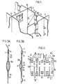
- - la figure 1 est une vue en perspective d'un fragment d'une grille d'assemblage combustible dont les ressorts peuvent être insérés par un dispositif suivant l'invention,
- - la figure 2 est une vue de détail montrant, en élévation, un fragment d'une plaquette de la grille de la figure 1, munie des ouvertures et des déformations nécessaires pour recevoir les ressorts,
- - les figures 3A et 3B sont des vues, respectivement en coupe suivant les lignes AA et BB de la figure 2, montrant respectivement un ressort double (à deux branches actives) et un ressort simple (dont une branche constitue ressort et l'autre constitue butée),
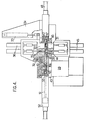
- - la figure 4 est un schéma de principe, en élévation et en coupe partielle suivant un plan vertical, montrant un dispositif de montage de ressort double,
- - la figure 5 est une vue à grande échelle d'une fraction de la figure 4,
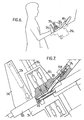
- - la figure 6 est une vue schématique en élévation d'un poste de travail comportant un dispositif de montage de ressort simple,
- - la figure 7 est une vue en élévation et en coupe partielle montrant le dispositif de montage de la figure 6,
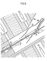
- - la figure 8 est une vue de détail à grande échelle d'un fragment de la figure 7, un ressort étant représenté au cours de son insertion.
- FIG. 1 is a perspective view of a fragment of a fuel assembly grid, the springs of which can be inserted by a device according to the invention,
- FIG. 2 is a detail view showing, in elevation, a fragment of a plate of the grid of FIG. 1, provided with the openings and deformations necessary to receive the springs,
- - Figures 3A and 3B are views, respectively in section along lines AA and BB of Figure 2, showing respectively a double spring (with two active branches) and a single spring (one branch of which constitutes a spring and the other of which constitutes stop),
- - Figure 4 is a block diagram, in eleva tion and in partial section along a vertical plane, showing a double spring mounting device,
- FIG. 5 is a large-scale view of a fraction of FIG. 4,
- FIG. 6 is a schematic elevation view of a work station comprising a simple spring mounting device,
- FIG. 7 is a view in elevation and in partial section showing the mounting device of FIG. 6,
- - Figure 8 is a detail view on a large scale of a fragment of Figure 7, a spring being shown during its insertion.
Les dispositifs qui seront décrits à titre d'exemples peuvent être utilisés notamment pour monter les ressorts montrés en figures 3A et 3B sur les plaquettes d'une grille du genre montré en figure 1. Cette grille 10 est constituée par des plaquettes 11, généralement en alliage à base de zirconium dénommé «Zirca- loy», assemblées à mi-fer et soudées en leurs points de raccordement 12.The devices which will be described by way of examples can be used in particular for mounting the springs shown in FIGS. 3A and 3B on the plates of a grid of the kind shown in FIG. 1. This
Chacune des plaquettes 11 comporte des bossages 13 d'appui de crayons de combustible (non représentés) et diverses ouvertures coopérant avec les ressorts destinés à appliquer les crayons sur les bossages. Sur la figure 1 apparaissent uniquement des ressorts doubles 15A qui s'insèrent dans des échancrures 14 des plaquettes débouchant sur l'une des tranches.Each of the
Sur la plaquette 11 représentée schématiquement en figure 2, ont été indiqués, de façon artificielle, différents types d'ouvertures et de déformations que l'on rencontre dans une grille 10. On voit sur cette figure les fentes 16 destinées à permettre l'assemblage à mi-fer, placées face à des intervalles de guidage délimités par des ergots 17. Une bande médiane verticale de la plaquette 11 qui porte deux bossages 13 dirigés d'un même côté est equipée d'une languette 18 de fixation de la grille sur un tube guide (non représenté) appartenant à l'ossature de l'assemblage. A gauche de cette bande munie de bossages 13 dirigés vers un seul côté de la plaquette est montrée une bande munie d'ouvertures destinées à recevoir un ressort simple 15B dont l'encombrement est indiqué en tirets. A gauche de cette bande en est montrée une autre, munie de bossages 13 faisant saillie des deux côtés de la plaquette, comme indiqué sur un des côtés de la cellule complète visible en figure 1. Une bande identique a été représentée immédiatement à droite de celle qui porte une languette de fixation 18. Enfin, la dernière bande à droite est munie d'une échancrure 14 destinée à recevoir un ressort double 1 5A. Les ailettes 21 indiquées en traits mixtes et apparaissant sur un des bords de la plaquette sont prévues uniquement sur certaines des plaquettes.On the
Comme le montre la figure 3A, chacun des ressorts 1 5A peut être mis en place en glissant ses branches de part et d'autre de la plaquette 11 jusqu'à ce que la boucle supérieure du ressort vienne au contact de la plaquette, au fond de l'échancrure 14. Des fenêtres 19 ménagées dans la plaquette (figures 2 et 3A) permettent de fixer les deux branches de ressort directement l'une sur l'autre à l'aide d'un point de soudure 20.As shown in Figure 3A, each of the springs 1 5A can be put in place by sliding its branches on either side of the
Le ressort simple 15B montré en figure 3B est de constitution dissymétrique. Sa branche 22 est similaire aux branches du ressort 15A. L'autre branche 23 est dessinée de façon à constituer une rotule délimitée par deux plis 24 susceptibles de venir en contact avec la branche 22 à travers des ouvertures 25 de la plaquette, pour éviter de transmettre les efforts de compression à celle-ci. Comme dans le cas précédent, les deux branches du ressort 15B sont soudées l'une à l'autre à travers des fenêtres 19 sur la grille terminée. Mais la boucle ne vient pas se placer au fond d'une échancrure, mais dans un prolongement de l'ouverture supérieure 19, ménagée par un des bossages 13. Il n'est donc pas possible de passer directement les branches 22 et 23 de part et d'autre de la plaquette.The
Cette suppression de l'échancrure, gênante pour ce qui est de l'insertion du ressort, est fréquemment indispensable car l'échancrure affaiblirait de façon excessive la plaquette à un emplacement où elle présente déjà des bossages 13 constitués par des crevés qui ont un rôle important dans le supportage, mais une action défavorable sur la résistance de la plaquette.This removal of the notch, which is troublesome with regard to the insertion of the spring, is frequently essential since the notch would excessively weaken the plate at a location where it already has
On décrira maintenant, successivement, deux dispositifs adaptés à la mise en place des ressorts 1 5A et 15B, respectivement. Naturellement un seul de ces dispositifs suffirait dans le cas où le mode d'insertion est le même pour tous les ressorts. Et, pour d'autres formes de ressorts ou de plaquettes, il pourrait être nécessaire de modifier ces dispositifs.We will now describe, successively, two devices adapted to the installation of the springs 1 5A and 15B, respectively. Naturally, only one of these devices would suffice if the insertion mode is the same for all the springs. And, for other forms of springs or plates, it may be necessary to modify these devices.
Le dispositif montré en figure 4, dont la fraction qui assure le positionnement précis et le soudage du ressort est montrée en figure 5, est destiné au montage des ressorts 1 5A. Ce dispositif comporte un bâti 29 dont est solidaire une mâchoire inférieure fixe 31. Une mâchoire supérieure mobile 30 est montée de façon à pouvoir tourner sur un axe 32 solidaire des mâchoires 30 et 31. Un vérin 33 de manoeuvre, par exemple pneumatique, est monté entre une console 34 solidaire de la mâchoire inférieure fixe 31 et la mâchoire supérieure mobile 30. Ce vérin permet de basculer la mâchoire 30 entre la position de travail dans laquelle elle est montrée en figures 4 et 5 et une position où elle dégage le poste de positionnement et de soudage du ressort, permettant ainsi de mettre en place ou d'enlever une plaquette 11.The device shown in Figure 4, the fraction of which ensures precise positioning and welding of the spring is shown in Figure 5, is intended for mounting the springs 1 5A. This device comprises a
La mâchoire inférieure 31 comporte des moyens pour recevoir une plaquette à la fois et la déplacer dans le sens de sa longueur, c'est-à-dire transversalement au plan des figures 4 et 5. Dans le mode de réalisation illustré, ces moyens comprennent un coulisseau 39 comportant des mors profilés 41. La plaquette est fixée par des moyens (non représentés) situés aux extrémités du mors inférieur. Les mors comprennent de plus une butée 42 de ressort, dont le rôle apparaîtra plus loin. Le coulisseau est porté par une glissière 43 liée au bâti à ses deux extrémités par des moyens non représentés. Le bâti porte encore des moyens d'avance du coulisseau par des égaux à l'intervalle qui sépare deux bandes successives de la plaquette 11.The
Dans la partie fixe du dispositif est ménagé un couloir 49 de guidage de chaque ressort à son tour, associé à des moyens pour déplacer le ressort le long du couloir vers la plaquette. Dans le mode de réalisation illustré en figure 4, ce couloir est ménagé dans une pièce solidaire du bâti et s'étend entre le poste de positionnement et de soudage et une chambre de réception d'un chargeur 50 dans lequel les ressorts 15A sont empilés, transversalement au plan de la figure. Le chargeur 50 a un profil interne qui épouse la forme des ressorts et il contient un ressort de compression (non représenté) qui repousse la pile de ressorts après chaque extraction d'un ressort de manière à en ramener un autre en face du couloir de guidage 49. Dans une variante de réalisation, l'alimentation en ressorts est effectuée grâce à une disposition en bande des ressorts, liés entre eux par des tenons qui sont cisaillés lors de l'introduction dans le couloir de guidage 49. Les moyens pour déplacer le ressort comportent un vérin 52 à double effet, par exemple pneumatique dont le piston se prolonge par une tige 51 terminée par une échancrure 53 destinée à venir s'appliquer contre la boucle supérieure du ressort 15A à insérer. Lors de la mise en oeuvre du vérin 52 à partir de la position de repos montrée en figure 4, la tige 51 repousse le ressort jusqu'à ce que ses branches viennent en appui contre la butée 42.In the fixed part of the device is formed a
Le dispositif montré en figure 4 est destiné non seulement à positionner les ressorts, mais aussi à les souder en place. Dans ce but, les mâchoires 30 et 31 portent chacune un jeu d'électrodes. La mâchoire supérieure 30 comprend deux électrodes 35 actionnables chacune par un vérin, par exemple pneumatique 36, permettant de les déplacer entre la position de repos où elles sont illustrées en fig. 4 et une position de travail où les électrodes reposent sur le ressort, face aux fenêtres 19 de la plaquette. De façon symétrique, la mâchoire inférieure 31 est munie de deux électrodes 44 actionnées par des vérins 45. Lorsque les deux jeux de vérins sont actionnés, les deux branches opposées du ressort 15A placé en face sont appliquées l'une contre l'autre à travers les fenêtres 19.The device shown in Figure 4 is intended not only to position the springs, but also to weld them in place. For this purpose, the
Bien que les moyens de déplacement du ressort guident celui-ci en le maintenant dans une orientation parallèle au plan de la plaquette vers son emplacement d'insertion, à partir d'une des tranches de la plaquette, il subsiste un risque d'accrochage de l'extrémité d'une branche du ressort par la fenêtre 19 la plus éloignée de la tranche d'introduction. Pour écarter ce risque, le dispositif montré en figure 4 comporte des masques 47 mobiles, destinés à recouvrir la fenêtre 19 pendant l'introduction du ressort 15A. Ces masques 47 sont constitués par deux tôles minces déplaçables par un vérin 48, par exemple pneumatique, entre la position rétractée où elles sont montrées en figure 4 et la position avancée où elles sont montrées en figure 5 et où elles recouvrent la fenêtre 19 et se terminent à mi-longueur de la plaquette. L'écartement de ces tôles est fixé par une cale (non représentée) à une valeur légèrement supérieure à l'épaisseur de la plaquette.Although the means for moving the spring guide the latter by keeping it in an orientation parallel to the plane of the plate towards its insertion location, from one of the edges of the plate, there remains a risk of catching the end of a branch of the spring through the
Le dispositif est évidemment complété par des moyens d'alimentation des électrodes de soudage en courant et par un mécanisme de commande en séquence des différents éléments, qui sera en général constitué par un automate programmable, bien qu'une commande manuelle par opérateur soit évidemment possible. On peut prévoir un dispositif de mise en vibration de coulisseau 39 afin de faciliter le positionnement du ressort. Dans tous les cas, le fonctionnement sera le suivant au cours de l'équipement d'une plaquette.The device is obviously supplemented by means for supplying current to the welding electrodes and by a mechanism for sequentially controlling the various elements, which will generally be constituted by a programmable automaton, although manual control by operator is obviously possible. . A device for vibrating the
La mâchoire supérieure 30 étant soulevée, une plaquette nue 11 est mise en place alors que le coulisseau occupe la position pour laquelle la première bande de la plaquette 11 fait face au couloir 49. La mâchoire supérieure est refermée, les électrodes des deux mâchoires étant dans la position montrée en figures 4 et 5. Les mors portant la plaquette sont alors emprisonnés et ne peuvent plus se déplacer que transversalement au plan de la figure. Si la première bande doit recevoir un ressort 1 5A, le vérin 48 est d'abord actionné pour amener les masques 47 dans la position montrée en figure 5, puis le vérin 52 est actionné pour amener la tige 41 de la position montrée en figure 4 à la position montrée en figure 5 et insérer un ressort 15A. Les vérins 36 et 45 sont actionnés pour appliquer les électrodes 35 et 44 contre les branches du ressort et les maintenir en position sur la plaquette. La tige 51 et les masques 47 sont rétractés par mise en action des vérins 52 et 48, le retrait des masques s'accompagnant de la venue en contact des deux branches du ressort 1 5A à travers les fenêtres 19, sous l'action des électrodes. Le soudage est alors effectué, puis les électrodes 35 et 44 sont rétractées. Les moyens de déplacement transversal du coulisseau 39 sont actionnés pour déplacer la plaquette soit d'un pas, soit de plusieurs pas, suivant que l'emplacement suivant de la plaquette est ou n'est pas équipé d'un ressort double, puis la séquence est répétée. Une fois la plaquette complètement équipée, la mâchoire supérieure 30 est ouverte pour permettre d'enlever la plaquette et de la remplacer par une plaquette nue.The
On décrira maintenant, en faisant référence aux figures 6 à 8, un dispositif permettant de mettre en place des ressorts en les introduisant non plus par une tranche terminale de la plaquette, mais par une ouverture de celle-ci. Un tel dispositif est donc notamment utilisable pour mettre en place les ressorts simples 1 5B sur les plaquettes 11.We will now describe, with reference to FIGS. 6 to 8, a device making it possible to set up springs by introducing them no longer by an end edge of the plate, but by an opening of the latter. Such a device is therefore in particular usable for installing the simple springs 1 5B on the
Pour cela, il est nécessaire d'introduire le ressort par un couloir qui maintient le ressort dans une orientation qui n'est pas celle du plan de la plaquette, tout en restant proche de cette orientation. De plus, le dispositif est avantageusement placé de façon que les forces de gravité agissant sur le ressort à insérer favorisent son insertion.For this, it is necessary to introduce the spring through a corridor which maintains the spring in an orientation which is not that of the plane of the wafer, while remaining close to this orientation. In addition, the device is advantageously placed so that the gravity forces acting on the spring to be inserted promote its insertion.
Le dispositif des figures 6 à 8 a une constitution générale qui se rapproche de celle déjà décrite en faisant référence aux figures 4 et 5 et les éléments correspondants seront désignés par le même numéro affecté de l'indice 1. Il comprend encore un bâti 291 sur lequel est fixée une mâchoire inférieure 311, portant un axe 321 autour duquel un vérin 331 permet de faire basculer une mâchoire supérieure 301. Mais le bâti est placé de façon que la plaquette à équiper 11 soit maintenue non pas horizontalement, mais avec un angle a qui sera généralement de l'ordre de 30°. De plus, on donne au couloir 491 une inclinaison par rapport au plan de la plaquette, généralement de l'ordre de 20°, et on le place de façon à guider la branche non active du ressort 15B vers la fenêtre d'introduction 19. On voit que le couloir présente une inclinaison totale sur l'horizontale de l'ordre de 50° environ qui permet au ressort de glisser per gravité le long de la plaquette 11 après arrêt de l'action de la tige d'introduction 511 (figure 7). On retrouve, dans le dispositif des figures 6 à 8, des masques 47i et le rôle du masque supérieur est ici particulièrement important du fait du risque accru d'accrochage de la branche supérieure du ressort 15B dans la fenêtre ou les fenêtres les plus éloignées de la zone d'introduction.The device of FIGS. 6 to 8 has a general constitution which is similar to that already described with reference to FIGS. 4 and 5 and the corresponding elements will be designated by the same number assigned with the index 1. It also includes a
Le fonctionnement du dispositif des figures 6 à 8 est très similaire à celui du dispositif des figures 4 et 5: les plaquettes à équiper, éventuellement déjà munies de leur ressort double, sont encore placées dans un coulisseau déplaçable par des moyens non représentés.The operation of the device in FIGS. 6 to 8 is very similar to that of the device in FIGS. 4 and 5: the plates to be fitted, possibly already provided with their double spring, are still placed in a slide displaceable by means not shown.
Les dispositifs qui viennent d'être décrits peuvent être intégrés à un ensemble de travail comprenant également un dispositif d'approvisionnement constitué par un ensemble de tiroirs de stockage placé à côté du bâti de chaque dispositif et ayant des tiroirs recevant, d'un côté, les plaquettes nues (ou déjà équipées d'un type de ressort) et les chargeurs de ressort pleins et, de l'autre, des tiroirs permettant de stocker les plaquettes équipées avant évacuation. L'automate séquentiel programmable de commande peut être de nature entièrement classique. Il sera généralement prévu pour effectuer toutes les opérations de contrôle requises, éventuellement en complétant le dispositif par des palpeurs non représentés.The devices which have just been described can be integrated into a working assembly also comprising a supply device constituted by a set of storage drawers placed next to the frame of each device and having drawers receiving, on one side, bare plates (or already equipped with a type of spring) and full spring chargers and, on the other, drawers for storing equipped plates before evacuation. The programmable sequential controller can be entirely conventional in nature. It will generally be provided to carry out all the required control operations, possibly by supplementing the device with probes not shown.
Claims (12)
Applications Claiming Priority (2)
| Application Number | Priority Date | Filing Date | Title |
|---|---|---|---|
| FR8217717A FR2535101A1 (en) | 1982-10-22 | 1982-10-22 | METHOD AND APPARATUS FOR PLACING HAIRPIN SPRINGS ON PLATES, IN PARTICULAR FOR FUEL ASSEMBLY GRIDS |
| FR8217717 | 1982-10-22 |
Publications (2)
| Publication Number | Publication Date |
|---|---|
| EP0108673A1 EP0108673A1 (en) | 1984-05-16 |
| EP0108673B1 true EP0108673B1 (en) | 1986-06-04 |
Family
ID=9278510
Family Applications (1)
| Application Number | Title | Priority Date | Filing Date |
|---|---|---|---|
| EP83402055A Expired EP0108673B1 (en) | 1982-10-22 | 1983-10-21 | Process and apparatus for placing hair-pin-shaped springs on plates, particularly for grids for combustibles |
Country Status (4)
| Country | Link |
|---|---|
| US (1) | US4633569A (en) |
| EP (1) | EP0108673B1 (en) |
| DE (1) | DE3363951D1 (en) |
| FR (1) | FR2535101A1 (en) |
Families Citing this family (2)
| Publication number | Priority date | Publication date | Assignee | Title |
|---|---|---|---|---|
| FR2564020B1 (en) * | 1984-05-10 | 1986-10-24 | Cogema Framatome Uranium Pechi | DEVICE FOR PLACING HAIRPIN SPRINGS ON PLATES, IN PARTICULAR FOR FUEL ASSEMBLY GRIDS |
| CN114603345A (en) * | 2022-03-29 | 2022-06-10 | 南京中拓科技有限公司 | Assembling device and assembling method for spring |
Family Cites Families (5)
| Publication number | Priority date | Publication date | Assignee | Title |
|---|---|---|---|---|
| US2629296A (en) * | 1948-02-10 | 1953-02-24 | Solo Products Corp | Machine for automatically carding curlers |
| US2629236A (en) * | 1949-05-19 | 1953-02-24 | Sunkist Growers Inc | Refrigerated beverage dispenser |
| US4261098A (en) * | 1979-05-29 | 1981-04-14 | Lincoln Walter B | Apparatus for clipping sheets together |
| FR2459759A1 (en) * | 1979-06-26 | 1981-01-16 | Petit Bernard | APPARATUS FOR AUTOMATICALLY CLASPING LAUNDRY CLIPS, OF THE TYPE CLAMPS WITH SPRINGS |
| FR2474229B1 (en) * | 1980-01-22 | 1986-08-22 | Commissariat Energie Atomique | SPACER GRILLE FOR FUEL ASSEMBLY OF NUCLEAR REACTOR |
-
1982
- 1982-10-22 FR FR8217717A patent/FR2535101A1/en active Granted
-
1983
- 1983-10-21 DE DE8383402055T patent/DE3363951D1/en not_active Expired
- 1983-10-21 EP EP83402055A patent/EP0108673B1/en not_active Expired
- 1983-10-24 US US06/545,012 patent/US4633569A/en not_active Expired - Fee Related
Also Published As
| Publication number | Publication date |
|---|---|
| FR2535101B1 (en) | 1985-03-08 |
| US4633569A (en) | 1987-01-06 |
| EP0108673A1 (en) | 1984-05-16 |
| FR2535101A1 (en) | 1984-04-27 |
| DE3363951D1 (en) | 1986-07-10 |
Similar Documents
| Publication | Publication Date | Title |
|---|---|---|
| FR3029127B1 (en) | DEVICE FOR LOADING A SPACING GRID WELDING TOOL | |
| EP0159228B1 (en) | Method and apparatus for welding nuclear fuel assembly grids | |
| FR2828428A1 (en) | Device for separating substrates prepared with cleavage planes, and associated method | |
| EP2140460B1 (en) | Container for transporting and/or storing nuclear material, said container including a mobile heat-conducting structure | |
| FR2533065A1 (en) | GRIPPING DEVICE FOR SIMULTANEOUSLY REMOVING A MULTIPLICITY OF FUEL BARS FROM A NUCLEAR FUEL ASSEMBLY | |
| EP0123607B1 (en) | Hold-down apparatus for a nuclear reactor | |
| EP0108673B1 (en) | Process and apparatus for placing hair-pin-shaped springs on plates, particularly for grids for combustibles | |
| EP0218494B1 (en) | Method and device for compacting a bundle of fuel rods | |
| EP0163568B1 (en) | Apparatus for placing hair-pin-shaped springs on plates, particularly for grids in combustible assemblies | |
| FR2690554A1 (en) | Device and method for mounting rods in a nuclear fuel assembly skeleton. | |
| EP2589474A1 (en) | Automated method for inserting insulating bodies in the cells of building blocks, and automatic insertion line for implementing same | |
| EP0230172B1 (en) | Gripper device for a rod bundle of a nuclear fuel assembly | |
| EP0244278B1 (en) | Method for loading a rod bundle of a nuclear fuel assembly into a canister, and installation to carry out this method | |
| EP0279741B1 (en) | Method and device for cutting irradiated fuel elements in a horizontal position, using a slidable blade holder | |
| EP1238396A1 (en) | Device and method for mounting a bracing grid of a fuel assembly for a nuclear reactor | |
| EP0435774B1 (en) | Device for loading and unloading a storage cassette with flat objects | |
| FR2513796A1 (en) | COMBUSTIBLE AND FERTILIZED NEEDLE FOR NUCLEAR REACTOR AND METHOD OF MANUFACTURING THE SAME | |
| EP0344051A1 (en) | Nuclear fuel assembly receiving and dismantling cell | |
| CH625724A5 (en) | ||
| EP3815113A1 (en) | Device for carrying out interventions on a nuclear fuel assembly | |
| FR3101485A3 (en) | Fuel cell stack assembly apparatus and method | |
| EP0156686A1 (en) | Supporting device for a nuclear fuel assembly in a reactor | |
| EP0384825B1 (en) | Spacer grid for a nuclear fuel assembly, and mounting method using said grid | |
| FR2683080A1 (en) | METHOD FOR ASSEMBLING A NUCLEAR FUEL ASSEMBLY AND APPARATUS THEREFOR. | |
| FR2721445A1 (en) | Machine for manufacturing electrical harnesses comprising simple connectors and its use. |
Legal Events
| Date | Code | Title | Description |
|---|---|---|---|
| PUAI | Public reference made under article 153(3) epc to a published international application that has entered the european phase |
Free format text: ORIGINAL CODE: 0009012 |
|
| AK | Designated contracting states |
Designated state(s): BE DE SE |
|
| 17P | Request for examination filed |
Effective date: 19840808 |
|
| RAP1 | Party data changed (applicant data changed or rights of an application transferred) |
Owner name: SOCIETE COGEMA, FRAMATOME ET URANIUM PECHINEY |
|
| GRAA | (expected) grant |
Free format text: ORIGINAL CODE: 0009210 |
|
| AK | Designated contracting states |
Kind code of ref document: B1 Designated state(s): BE DE SE |
|
| REF | Corresponds to: |
Ref document number: 3363951 Country of ref document: DE Date of ref document: 19860710 |
|
| PLBE | No opposition filed within time limit |
Free format text: ORIGINAL CODE: 0009261 |
|
| STAA | Information on the status of an ep patent application or granted ep patent |
Free format text: STATUS: NO OPPOSITION FILED WITHIN TIME LIMIT |
|
| 26N | No opposition filed | ||
| PGFP | Annual fee paid to national office [announced via postgrant information from national office to epo] |
Ref country code: BE Payment date: 19931027 Year of fee payment: 11 |
|
| PGFP | Annual fee paid to national office [announced via postgrant information from national office to epo] |
Ref country code: DE Payment date: 19931228 Year of fee payment: 11 |
|
| PG25 | Lapsed in a contracting state [announced via postgrant information from national office to epo] |
Ref country code: BE Effective date: 19941031 |
|
| EAL | Se: european patent in force in sweden |
Ref document number: 83402055.4 |
|
| BERE | Be: lapsed |
Owner name: SOC. COGEMA FRAMATOME ET URANIUM PECHINEY Effective date: 19941031 |
|
| PG25 | Lapsed in a contracting state [announced via postgrant information from national office to epo] |
Ref country code: DE Effective date: 19950701 |
|
| PGFP | Annual fee paid to national office [announced via postgrant information from national office to epo] |
Ref country code: SE Payment date: 19961017 Year of fee payment: 14 |
|
| PG25 | Lapsed in a contracting state [announced via postgrant information from national office to epo] |
Ref country code: SE Free format text: LAPSE BECAUSE OF NON-PAYMENT OF DUE FEES Effective date: 19971022 |
|
| EUG | Se: european patent has lapsed |
Ref document number: 83402055.4 |