EP0347101B1 - Endotriachealröhre und Massenspektrometer - Google Patents
Endotriachealröhre und Massenspektrometer Download PDFInfo
- Publication number
- EP0347101B1 EP0347101B1 EP89305793A EP89305793A EP0347101B1 EP 0347101 B1 EP0347101 B1 EP 0347101B1 EP 89305793 A EP89305793 A EP 89305793A EP 89305793 A EP89305793 A EP 89305793A EP 0347101 B1 EP0347101 B1 EP 0347101B1
- Authority
- EP
- European Patent Office
- Prior art keywords
- passage
- mass spectrometer
- tracheal
- ion
- housing
- Prior art date
- Legal status (The legal status is an assumption and is not a legal conclusion. Google has not performed a legal analysis and makes no representation as to the accuracy of the status listed.)
- Expired - Lifetime
Links
- 239000007789 gas Substances 0.000 claims description 99
- 150000002500 ions Chemical class 0.000 claims description 88
- 238000005070 sampling Methods 0.000 claims description 46
- 210000004072 lung Anatomy 0.000 claims description 29
- 230000000241 respiratory effect Effects 0.000 claims description 15
- 238000010276 construction Methods 0.000 claims description 10
- 210000005092 tracheal tissue Anatomy 0.000 claims description 10
- 210000003437 trachea Anatomy 0.000 claims description 6
- 238000003780 insertion Methods 0.000 claims description 5
- 230000037431 insertion Effects 0.000 claims description 5
- 238000012544 monitoring process Methods 0.000 claims description 5
- 230000002093 peripheral effect Effects 0.000 claims description 5
- 238000000605 extraction Methods 0.000 claims description 3
- 210000000214 mouth Anatomy 0.000 claims 3
- 239000012634 fragment Substances 0.000 claims 1
- 239000000523 sample Substances 0.000 description 29
- 238000000034 method Methods 0.000 description 25
- 230000006870 function Effects 0.000 description 15
- 230000000747 cardiac effect Effects 0.000 description 12
- 101100243025 Arabidopsis thaliana PCO2 gene Proteins 0.000 description 11
- 230000001133 acceleration Effects 0.000 description 10
- 239000004020 conductor Substances 0.000 description 10
- 230000002802 cardiorespiratory effect Effects 0.000 description 9
- 238000001816 cooling Methods 0.000 description 7
- 241000894007 species Species 0.000 description 7
- XKRFYHLGVUSROY-UHFFFAOYSA-N Argon Chemical compound [Ar] XKRFYHLGVUSROY-UHFFFAOYSA-N 0.000 description 6
- 239000002245 particle Substances 0.000 description 6
- 210000001519 tissue Anatomy 0.000 description 6
- 238000004458 analytical method Methods 0.000 description 5
- 238000009423 ventilation Methods 0.000 description 5
- 206010059411 Prolonged expiration Diseases 0.000 description 4
- 239000008280 blood Substances 0.000 description 4
- 210000004369 blood Anatomy 0.000 description 4
- 239000000835 fiber Substances 0.000 description 4
- 230000004907 flux Effects 0.000 description 4
- 238000005259 measurement Methods 0.000 description 4
- 230000007246 mechanism Effects 0.000 description 4
- 239000000203 mixture Substances 0.000 description 4
- 206010002091 Anaesthesia Diseases 0.000 description 3
- 230000037005 anaesthesia Effects 0.000 description 3
- 229910052786 argon Inorganic materials 0.000 description 3
- 239000000919 ceramic Substances 0.000 description 3
- 230000008859 change Effects 0.000 description 3
- 230000000694 effects Effects 0.000 description 3
- 238000001356 surgical procedure Methods 0.000 description 3
- 238000012360 testing method Methods 0.000 description 3
- 238000011144 upstream manufacturing Methods 0.000 description 3
- XEEYBQQBJWHFJM-UHFFFAOYSA-N Iron Chemical group [Fe] XEEYBQQBJWHFJM-UHFFFAOYSA-N 0.000 description 2
- KDLHZDBZIXYQEI-UHFFFAOYSA-N Palladium Chemical compound [Pd] KDLHZDBZIXYQEI-UHFFFAOYSA-N 0.000 description 2
- 208000003443 Unconsciousness Diseases 0.000 description 2
- HSFWRNGVRCDJHI-UHFFFAOYSA-N alpha-acetylene Natural products C#C HSFWRNGVRCDJHI-UHFFFAOYSA-N 0.000 description 2
- QVGXLLKOCUKJST-UHFFFAOYSA-N atomic oxygen Chemical compound [O] QVGXLLKOCUKJST-UHFFFAOYSA-N 0.000 description 2
- 230000005540 biological transmission Effects 0.000 description 2
- 230000017531 blood circulation Effects 0.000 description 2
- 238000004364 calculation method Methods 0.000 description 2
- 230000004087 circulation Effects 0.000 description 2
- 125000002534 ethynyl group Chemical group [H]C#C* 0.000 description 2
- 229920002457 flexible plastic Polymers 0.000 description 2
- 230000001771 impaired effect Effects 0.000 description 2
- 238000002955 isolation Methods 0.000 description 2
- 230000007257 malfunction Effects 0.000 description 2
- 239000000463 material Substances 0.000 description 2
- 239000001301 oxygen Substances 0.000 description 2
- 229910052760 oxygen Inorganic materials 0.000 description 2
- 230000035479 physiological effects, processes and functions Effects 0.000 description 2
- 230000009325 pulmonary function Effects 0.000 description 2
- 230000004202 respiratory function Effects 0.000 description 2
- 230000029058 respiratory gaseous exchange Effects 0.000 description 2
- 210000002345 respiratory system Anatomy 0.000 description 2
- 230000000007 visual effect Effects 0.000 description 2
- 208000028399 Critical Illness Diseases 0.000 description 1
- 208000032365 Electromagnetic interference Diseases 0.000 description 1
- 102000001554 Hemoglobins Human genes 0.000 description 1
- 108010054147 Hemoglobins Proteins 0.000 description 1
- 229910000831 Steel Inorganic materials 0.000 description 1
- WOIHABYNKOEWFG-UHFFFAOYSA-N [Sr].[Ba] Chemical compound [Sr].[Ba] WOIHABYNKOEWFG-UHFFFAOYSA-N 0.000 description 1
- 230000002159 abnormal effect Effects 0.000 description 1
- 230000036760 body temperature Effects 0.000 description 1
- 210000000748 cardiovascular system Anatomy 0.000 description 1
- 150000001875 compounds Chemical class 0.000 description 1
- 238000009833 condensation Methods 0.000 description 1
- 230000005494 condensation Effects 0.000 description 1
- 239000000356 contaminant Substances 0.000 description 1
- 238000012937 correction Methods 0.000 description 1
- 230000008878 coupling Effects 0.000 description 1
- 238000010168 coupling process Methods 0.000 description 1
- 238000005859 coupling reaction Methods 0.000 description 1
- 239000013078 crystal Substances 0.000 description 1
- 238000010586 diagram Methods 0.000 description 1
- 230000004069 differentiation Effects 0.000 description 1
- 201000010099 disease Diseases 0.000 description 1
- 208000037265 diseases, disorders, signs and symptoms Diseases 0.000 description 1
- 239000003814 drug Substances 0.000 description 1
- 229940079593 drug Drugs 0.000 description 1
- 230000009977 dual effect Effects 0.000 description 1
- 230000004064 dysfunction Effects 0.000 description 1
- 230000002526 effect on cardiovascular system Effects 0.000 description 1
- 230000005684 electric field Effects 0.000 description 1
- 230000008030 elimination Effects 0.000 description 1
- 238000003379 elimination reaction Methods 0.000 description 1
- 230000029142 excretion Effects 0.000 description 1
- 238000001125 extrusion Methods 0.000 description 1
- 238000011010 flushing procedure Methods 0.000 description 1
- 238000013467 fragmentation Methods 0.000 description 1
- 238000006062 fragmentation reaction Methods 0.000 description 1
- 238000004868 gas analysis Methods 0.000 description 1
- 239000003193 general anesthetic agent Substances 0.000 description 1
- 239000011521 glass Substances 0.000 description 1
- 230000013632 homeostatic process Effects 0.000 description 1
- 210000005240 left ventricle Anatomy 0.000 description 1
- 230000008338 local blood flow Effects 0.000 description 1
- 238000012423 maintenance Methods 0.000 description 1
- 230000014759 maintenance of location Effects 0.000 description 1
- 238000004519 manufacturing process Methods 0.000 description 1
- 230000037323 metabolic rate Effects 0.000 description 1
- 239000010445 mica Substances 0.000 description 1
- 229910052618 mica group Inorganic materials 0.000 description 1
- 238000002156 mixing Methods 0.000 description 1
- 238000006213 oxygenation reaction Methods 0.000 description 1
- 229910052763 palladium Inorganic materials 0.000 description 1
- 230000010412 perfusion Effects 0.000 description 1
- 238000012545 processing Methods 0.000 description 1
- 230000002685 pulmonary effect Effects 0.000 description 1
- 238000005086 pumping Methods 0.000 description 1
- 238000004445 quantitative analysis Methods 0.000 description 1
- 239000010453 quartz Substances 0.000 description 1
- 239000000700 radioactive tracer Substances 0.000 description 1
- 230000004044 response Effects 0.000 description 1
- 230000000979 retarding effect Effects 0.000 description 1
- 210000005241 right ventricle Anatomy 0.000 description 1
- 238000007789 sealing Methods 0.000 description 1
- 230000035945 sensitivity Effects 0.000 description 1
- VYPSYNLAJGMNEJ-UHFFFAOYSA-N silicon dioxide Inorganic materials O=[Si]=O VYPSYNLAJGMNEJ-UHFFFAOYSA-N 0.000 description 1
- 230000005236 sound signal Effects 0.000 description 1
- 125000006850 spacer group Chemical group 0.000 description 1
- 230000006641 stabilisation Effects 0.000 description 1
- 238000011105 stabilization Methods 0.000 description 1
- 239000003381 stabilizer Substances 0.000 description 1
- 229910001220 stainless steel Inorganic materials 0.000 description 1
- 239000010935 stainless steel Substances 0.000 description 1
- 239000010959 steel Substances 0.000 description 1
- 230000002861 ventricular Effects 0.000 description 1
Images

Classifications
-
- A—HUMAN NECESSITIES
- A61—MEDICAL OR VETERINARY SCIENCE; HYGIENE
- A61B—DIAGNOSIS; SURGERY; IDENTIFICATION
- A61B5/00—Measuring for diagnostic purposes; Identification of persons
-
- A—HUMAN NECESSITIES
- A61—MEDICAL OR VETERINARY SCIENCE; HYGIENE
- A61B—DIAGNOSIS; SURGERY; IDENTIFICATION
- A61B5/00—Measuring for diagnostic purposes; Identification of persons
- A61B5/02—Detecting, measuring or recording for evaluating the cardiovascular system, e.g. pulse, heart rate, blood pressure or blood flow
- A61B5/026—Measuring blood flow
- A61B5/029—Measuring blood output from the heart, e.g. minute volume
-
- A—HUMAN NECESSITIES
- A61—MEDICAL OR VETERINARY SCIENCE; HYGIENE
- A61B—DIAGNOSIS; SURGERY; IDENTIFICATION
- A61B5/00—Measuring for diagnostic purposes; Identification of persons
- A61B5/02—Detecting, measuring or recording for evaluating the cardiovascular system, e.g. pulse, heart rate, blood pressure or blood flow
- A61B5/0205—Simultaneously evaluating both cardiovascular conditions and different types of body conditions, e.g. heart and respiratory condition
-
- A—HUMAN NECESSITIES
- A61—MEDICAL OR VETERINARY SCIENCE; HYGIENE
- A61M—DEVICES FOR INTRODUCING MEDIA INTO, OR ONTO, THE BODY; DEVICES FOR TRANSDUCING BODY MEDIA OR FOR TAKING MEDIA FROM THE BODY; DEVICES FOR PRODUCING OR ENDING SLEEP OR STUPOR
- A61M16/00—Devices for influencing the respiratory system of patients by gas treatment, e.g. ventilators; Tracheal tubes
- A61M16/04—Tracheal tubes
- A61M16/0434—Cuffs
- A61M16/0454—Redundant cuffs
- A61M16/0459—Redundant cuffs one cuff behind another
-
- A—HUMAN NECESSITIES
- A61—MEDICAL OR VETERINARY SCIENCE; HYGIENE
- A61M—DEVICES FOR INTRODUCING MEDIA INTO, OR ONTO, THE BODY; DEVICES FOR TRANSDUCING BODY MEDIA OR FOR TAKING MEDIA FROM THE BODY; DEVICES FOR PRODUCING OR ENDING SLEEP OR STUPOR
- A61M16/00—Devices for influencing the respiratory system of patients by gas treatment, e.g. ventilators; Tracheal tubes
- A61M16/04—Tracheal tubes
- A61M16/0488—Mouthpieces; Means for guiding, securing or introducing the tubes
- A61M16/049—Mouthpieces
- A61M16/0493—Mouthpieces with means for protecting the tube from damage caused by the patient's teeth, e.g. bite block
-
- A—HUMAN NECESSITIES
- A61—MEDICAL OR VETERINARY SCIENCE; HYGIENE
- A61M—DEVICES FOR INTRODUCING MEDIA INTO, OR ONTO, THE BODY; DEVICES FOR TRANSDUCING BODY MEDIA OR FOR TAKING MEDIA FROM THE BODY; DEVICES FOR PRODUCING OR ENDING SLEEP OR STUPOR
- A61M16/00—Devices for influencing the respiratory system of patients by gas treatment, e.g. ventilators; Tracheal tubes
- A61M16/08—Bellows; Connecting tubes ; Water traps; Patient circuits
- A61M16/0816—Joints or connectors
- A61M16/0841—Joints or connectors for sampling
- A61M16/0858—Pressure sampling ports
-
- A—HUMAN NECESSITIES
- A61—MEDICAL OR VETERINARY SCIENCE; HYGIENE
- A61M—DEVICES FOR INTRODUCING MEDIA INTO, OR ONTO, THE BODY; DEVICES FOR TRANSDUCING BODY MEDIA OR FOR TAKING MEDIA FROM THE BODY; DEVICES FOR PRODUCING OR ENDING SLEEP OR STUPOR
- A61M16/00—Devices for influencing the respiratory system of patients by gas treatment, e.g. ventilators; Tracheal tubes
- A61M16/0003—Accessories therefor, e.g. sensors, vibrators, negative pressure
- A61M2016/0027—Accessories therefor, e.g. sensors, vibrators, negative pressure pressure meter
-
- A—HUMAN NECESSITIES
- A61—MEDICAL OR VETERINARY SCIENCE; HYGIENE
- A61M—DEVICES FOR INTRODUCING MEDIA INTO, OR ONTO, THE BODY; DEVICES FOR TRANSDUCING BODY MEDIA OR FOR TAKING MEDIA FROM THE BODY; DEVICES FOR PRODUCING OR ENDING SLEEP OR STUPOR
- A61M2230/00—Measuring parameters of the user
- A61M2230/40—Respiratory characteristics
- A61M2230/43—Composition of exhalation
- A61M2230/432—Composition of exhalation partial CO2 pressure (P-CO2)
-
- A—HUMAN NECESSITIES
- A61—MEDICAL OR VETERINARY SCIENCE; HYGIENE
- A61M—DEVICES FOR INTRODUCING MEDIA INTO, OR ONTO, THE BODY; DEVICES FOR TRANSDUCING BODY MEDIA OR FOR TAKING MEDIA FROM THE BODY; DEVICES FOR PRODUCING OR ENDING SLEEP OR STUPOR
- A61M2230/00—Measuring parameters of the user
- A61M2230/40—Respiratory characteristics
- A61M2230/43—Composition of exhalation
- A61M2230/435—Composition of exhalation partial O2 pressure (P-O2)
Definitions
- This invention relates to a device which measures the quantity and composition of inhaled and expired gases from a conscious or unconscious human subject and then computes the pulmonary function and cardiac output of the subject from this data information.
- a device is known for example from document US-A-3 799 149.
- the function of the cardio-vascular and respiratory system is to supply oxygenated blood to the body tissues and to remove the CO2 produced by the tissues for excretion by ventilation of the lungs.
- the amount of blood pumped or vented and the amount of O2 and CO2 in the blood, as well as the volume of lung ventilation, are critical reflections of the adequacy of the circulatory and respiratory function.
- Invasive systems are available, but cannot be routinely used because the insertion procedure (via catheter or the like) is time-consuming and involves risk.
- Non-invasive devices such as the ultrasonic Doppler device, have been developed, but cannot be used routinely and are unable to continuously accurately determine the cardio-respiratory function.
- a gas sampling device for use in sampling respiratory gases from a human subject, which device includes a tube for insertion into the mouth of said human subject, the said tube having an upper end provided with means for connecting the said device to apparatus for analyzing the gases sampled and a lower end; characterised in that the said tube is of double-walled construction along its entire length and comprises inner and outer tubular elements, the interior of the said inner tubular element defining a central passage therethrough, means dividing the space between the inner and outer tubular elements into a plurality of elongate peripheral passages extending throughout the length of the double-walled tube, and a plurality of openings in a lower end portion of the said inner tubular element, each opening communicating respectively with the said passages, and also in that the said device further includes a capillary restriction member positioned within the said central passage, which member has a plurality of capillary openings therein for restricting the flow of air through said central passage.
- apparatus for sampling and analyzing respiratory gases from a human subject comprising a gas sampling device for insertion in the mouth of a human subject for use in sampling such respiratory gases, the said gas sampling device comprising a device according to the first aspect of the present invention, a miniature motor pump mass spectrometer module including a mass spectrometer, means connecting the mass spectrometer to a vacuum source, a differential pressure transducer, connecting means whereby samples of respiratory gases are directed from the said gas sampling device to the said mass spectrometer and/or the said differential pressure transducer, and electronic circuitry cooperating with the said mass spectrometer and the said pressure transducer for analyzing the lung gases and lung capacity of the human subject.
- a specially designed endotracheal tube embodying the present invention has several auxiliary passages along its length.
- the ventilation function of the endotracheal tube is not altered, and the sample gases are circulated through the auxiliary passages to the mass spectrometer for quantitative analysis.
- the endotracheal tube is preferably a disposable item and may be readily detached from the mass spectrometer motor pump module.
- One possible embodiment provides a non-invasive device which can continuously measure the quantity and composition of the inhaled and expired gases from a human subject, and then calculate the pulmonary function and cardiac output from this data.
- such a device may be designed to provide a non-invasive system for determining the cardio-respiratory function comprised of a specially designed endotracheal tube having a miniature mass spectrometer mounted thereon, which is operable to continuously measure O2, CO2, total volume and temperature of respired air, as well as tissue PO2 and PCO2 and other gases exchanged from the tracheal tissue compartment. It will be appreciated that such measurements provide the data to permit rapid calculation of the cardiac output, as well as a determination of the adequacy of tissue perfusion.
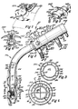
- the apparatus 10 is comprised of a flexible, preferably disposable, endotracheal tube 11 formed of suitable insert flexible plastic material, which is detachably connected to a motor pump and mass spectrometer module 12.
- the endotracheal tube 11 is comprised of an inner tube 13 and an outer tube 14.
- the double wall endotracheal tube 11 may be formed in any conventional manufacturing operation, such as a single-piece extrusion, or the endotracheal tube structure may be assembled from two tubes.
- the inner tube 13 defines a central passage 15 throughout its length and the central passage serves to ventilate the lungs in the manner of a conventional endotracheal tube.
- the inner tube 13 and outer tube 14 are interconnected together by a plurality of elongate interconnecting wall elements 16, which cooperate with the inner and outer tubes to divide the inter-tubular space into a plurality of circumferentially arranged passages.
- the inner and outer tubes are joined together at their respective lower ends, as at 17, while the upper ends of the inner and outer tubes are provided with and connected to an outturned rigid annular member 18, as best seen in Figure 15.
- the interconnecting wall elements 16 divide the inner tubular space into circumferentially arranged passages 19 through 26, respectively. These passages extend throughout the length of the endotracheal tube.
- a capillary restriction member 27 is positioned within the inner tube 13 adjacent the lower end 17 of the endotracheal tube and is provided with a plurality of capillaries or passages 28 therethrough. Referring now to Figures 2 and 4, it will be seen that the capillaries or passages 28 extend axially through the capillary restriction member 27 so that gases flowing through the passage 15 must pass through the capillaries 28. It will be appreciated that a pressure differential exists on opposite sides or ends of the capillary restriction member 27.
- the lower end portion of the endotracheal tube 11 is provided with an opening 29 in the inner tube 13 thereof, which communicates with the passage 19.
- Inhaled and expired gases from the human subject pass through the opening 30 into the passage 20 and flow in an upward direction so that passage 20 defines a sample passage.
- a portion of these sample gases is returned through the passage 19 and is discharged through the opening 29 into the lower tracheal area. Therefore, the passage 19 constitutes a return passage, and the gases flow in a downward or return direction.
- the inner tube 13 has an opening 31 therein, located above the capillary restriction member 27, which communicates with the passage 21.
- the passages 21 and 23 are connected to a differential pressure transducer for sensing and analyzing the gaseous pressure located below and above the capillary restriction member to thereby determine the lung volume or capacity.
- the outer tube 14 has a pair of flexible sleeve-like members 33 secured thereto adjacent the lower end portion of the endotracheal tube. These flexible sleeve-like members 33 are longitudinally spaced apart, and each has its upper annular edge portion 34 and its lower annular edge sealingly secured to the outer wall. The volumetric space located between each sleeve-like member 33 and the outer tube defines a chamber 36. Thus, each sleeve-like member 33 cooperates with the outer tube 14 to define a pair of inflatable balloons that may be selectively inflated and deflated by the operator.
- the outer tube 14 has a pair of longitudinally spaced apart openings 37 therein, each communicating with one of the chambers 36. Each opening also communicates with the passage 22, through which air may be passed to inflate each of the respective balloons 33 or to allow the balloons to be deflated.
- the balloons provide a dual function, one of which is to engage the tracheal wall of the human subject and function as a retaining means.
- the inflatable balloons 33 also cooperate with the tracheal wall of the human subject to define a tracheal wall sampling cell for measuring tracheal tissue O2 and CO2, which closely reflect arterial PO2 and provide an approximation of arterial PCO2 because the metabolic rate of the trachea is very low.
- the sleeve-like members or balloons 33 are illustrated in an inflated condition for engaging the trachea wall 38. These balloons 33 cooperate with the tracheal wall 38 to define a tracheal sampling cell 39 defined by the volumetric space located between the inflated balloons 33, the outer tube 14, and the tracheal wall 38.
- the outer tube 14 has an opening 40 therein, which communicates with the passage 24.
- the outer tube 14 also has an opening 41 therein, which communicates with the passage 25.
- the opening 40 intercommunicates the passage 24 with the tracheal sampling cell 39, while the opening 41 intercommunicates the passage 25 with the tracheal sampling cell.
- Sample gases from the tracheal cell flow upwardly through the sample passage 24 for analysis by the mass spectrometer, while tracheal sample gases are returned through the return passage 25 to the tracheal sampling cell.
- the upper end of the endotracheal tube is detachably connected to the motor pump and mass spectrometer module 12 by means of a manifold unit 42, which constitutes a component of the pump and mass spectrometer module.
- the manifold unit 42 includes a manifold body 43 having a reduced portion 43a, which projects into the inner tube 13 of the endotracheal tube 11.
- the manifold body has an external threaded portion 44, which is threadedly engaged by an internally threaded nut 45 having an inturned annular lip 45a.
- the inturned annular lip 45a engages the rigid annular member 18 secured to the upper end of the endotracheal tube and releasably secures the endotracheal tube to the manifold unit.
- the rigid annular member 18 has openings therein which are in registry with the respective passages of the endotracheal tube.
- the manifold body 43 has an L-shaped passage 46 therethrough, which extends through the reduced portion 43a and communicates with the large ventilating passage 15 of the inner tube 13.
- the manifold body is provided with a fitting 47 having a flexible hose 48 connected thereto, which is connected to a source of oxygen and anesthesia gas for ventilating the lungs of the human subject in a conventional manner, as best seen in Figure 17. It will, therefore, be seen that a mixture of oxygen and anesthesia gas is circulated through the passage 46 and into the ventilation passage 15 of the endotracheal tube for circulation to the respiratory system of the human subject when the human subject is anesthetized.
- the manifold body 43 is provided with a passage 49, which communicates with the sample passage 20 of the endotracheal tube 11.
- the manifold body is also provided with a passage 50, a passage 51, and a passage 52 therein.
- Passage 50 communicates with the return passage 19 in the endotracheal tube
- passage 51 communicates with the tracheal sample passage 24 of the endotracheal tube.
- Passage 52 in the manifold body communicates with the passage 25 of the endotracheal tube and returns tracheal tissue sample gases to the tracheal sampling cell 39.
- the manifold body 43 is also provided with passages 53, 59, and 56 therein, as best seen in Figure 7.
- Passage 53 communicates with passage 21 of the endotracheal tube and passage 56 communicates with passage 23 therein.
- Passage 59 communicates with passage 22 in the endotracheal tube, through which air under pressure passes to inflate or deflate the balloons 33.
- the gas pressure from the zone located below and above the capillary restriction member 27, respectively passes through the passages 53 and 56 to a differential pressure transducer where the lung capacity or volume is determined.
- the passage 53 is provided with a fitting 54 having a hose 55 attached thereto which, in turn, is connected to the differential pressure transducer.
- the passage 56 is provided with a fitting 57 having a hose 58 connected thereto, which is also connected in communicating relation with the pressure transducer.
- the passage 59 is provided with a fitting 60 having a hose 61 connected thereto, which is connected to a suitable small pump or similar pressure producing device, which is operable for inflating and deflating the balloons 33.
- the manifold unit 43 is also provided with a cylindrical recess 62 therethrough, which accommodates a rotatable valve 63.
- the rotatable valve 63 includes a generally cylindrical valve body 64 having a pair of spaced apart valve ports 65 and 66 therethrough, as best seen in Figures 8, 9, 14, and 15.
- the valve body 64 is provided with a small handle 67 at one end thereof to facilitate the rotation of the valve body in the manifold body.
- the valve body is also provided with axially spaced apart seals 68 of well-known construction, as best seen in Figure 8.
- a photoelectric position sensor unit 69 is secured to the valve body 64 and is provided with suitable electrical conductors for sensing the position of the valve body during operation of the gas-sensing apparatus 10.
- valve body is rotatable through an arc of 90 degrees to selectively intercommunicate the passages 49 and 50 with the mass spectrometer or to intercommunicate the passages 51 and 52 with the mass spectrometer device.
- This arrangement permits lung gases to be sampled and measured or, alternatively, tracheal tissue gases to be sampled and measured.
- the photoelectric sensor unit 69 will produce a visual signal indicating which sampling procedure is being monitored.
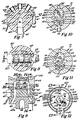
- the manifold unit is connected to an air driven gear motor pump unit 71, which is comprised of a generally cylindrically shaped motor pump body 72. Any suitable means, such as locking pins or the like, may be used to detachably secure the gear motor pump unit 71 to the manifold unit 62.
- the motor pump body 72 has a hollow interior provided with a divider plate 73 that divides the interior of the pump body into a motor chamber 74 and a pump chamber 75.
- the divider plate 73 engages an annular shoulder 72a in the pump body 72 for properly positioning the divider plate.
- the divider plate 73 has spaced apart axle pins 76 and 77 projecting from one surface thereof.
- the axle pins 76 and 77 project to the motor chamber 74, and each defines the center of a pair of cylindrical sub-chambers of the motor chamber.
- the divider plate 73 also has spaced apart axle pins 78 and 79 extending from the other surface thereof and projecting into the pump chamber 75. It will also be noted that the axle pins 78, 79 each define the center of a pair of sub-chambers of the pump chamber. It will further be noted that the axle pin 76 is disposed in coaxial relation with the axle pin 78, while the axle pin 77 is disposed in coaxial relation with axle pin 79.
- the motor pump body 72 is provided with a pair of laterally spaced apart axially extending passages 80 and 81 therein.
- the motor pump body 72 is also provided with an axially extending passage 82 therein and a radially extending passage 83 therein.
- the passages 80 and 81 communicate with the pump chamber 75, while the passages 82 and 83 communicate with the motor chamber 74.
- the passage 80 defines a sample passage through which sample gases from either the lung or tracheal sampling cell are directed, while the passage 81 defines a return passage through which lung gas samples or tracheal tissue gas samples are returned.
- the passage 82 defines an air inlet passage, which provides the motive power for driving the motor pump unit.
- the air passage 83 defines an outlet passage through which the air under pressure for driving the motor pump unit is discharged.
- the pump body is provided with a fitting 84 having a hose 85 connected thereto through which air is discharged from the air outlet passage 83.
- an upper drive gear 86 has a central opening 87 therein and is journaled on the axle pin 76 for rotation relative thereto.
- Drive gear 86 is provided with a plurality of gear lobes 88 symmetrically arranged and disposed in meshing relation with a lower driven gear 89.
- the lower driven gear 89 is provided with a central opening 90 and is journaled on axle pin 77.
- the lower driven gear 89 is also provided with gear lobes 91, each having a magnetic element 92 embedded therein.
- the drive gears 86 and 89 are shaped to be positioned within the motor chamber 74 so that the outer peripheries of each gear lobe are disposed closely adjacent the inner surfaces of the motor chamber.
- the axis rotation of the drive gear 86 and the driven gear 89 each define the center of the sub-chambers of the motor chamber 74.
- the pump chamber 75 is provided with a lower driven gear 93 having a central opening 94 therein and is journaled on axle pin 79.
- the lower driven gear 93 has a plurality of symmetrically arranged gear lobes 95, each having one of a plurality of soft iron core elements 96 embedded therein.
- the driven lower gear 93 in the pump chamber 75 is disposed in meshing relation with a driven upper gear 97 having a central opening 98 therein and journaled on axle pin 78.
- the driven gear 97 is also provided with gear lobes 99. It will be noted that the outer peripheral surfaces of the gear lobes of the driven gear 93 and the driven gear 97 are disposed closely adjacent the inner surfaces of the pump chamber 75. It will also be noted that, when the drive gear 86 of the air driven motor pump is driven by a stream of air under pressure introduced through the passage 82, gear 86 will drive the gear 89 and this rotating motive force will be transmitted by the interacting magnetic elements and soft iron core elements 92 and 96, respectively, to drive the lower gear 93 and, ultimately, the gear 97.
- the air stream for driving the motor unit is constantly being exhausted through the air passage 83 during operation of the motor unit and the pump unit.
- the motor pump body 22 is provided with a closure plate 110 having a central outlet opening 111 therein. Gas samples from either the lungs or the tracheal tissue sample cell are exhausted from the pump chamber through the outlet opening 111 into the mass spectrometer device 100.
- the motor pump unit 71 is detachably connected to a miniature mass spectrometer device 100, which includes a housing or body 101 of generally cylindrical configuration formed of stainless steel or the like.
- a miniature mass spectrometer device 100 which includes a housing or body 101 of generally cylindrical configuration formed of stainless steel or the like.
- the mass spectrometer housing 101 will be connected to the motor pump body 72 by any suitable releasable connecting means, such as coupling pins or the like, to permit easy and ready connection and disconnection of these units.
- the mass spectrometer housing 101 is of double wall construction and includes an outer cylindrical wall 102 and an inner cylindrical wall 103 spaced from the outer wall to define a generally cylindrical cooling chamber 104 therebetween.
- the housing 101 also includes a front end wall 105 integral with the cylindrical inner and outer walls.
- a generally circular ceramic header 106 defines the rear wall of the housing 101 and engages the double cylindrical walls thereof in sealing relation therewith.
- the front end wall 105 is provided with an axial opening 107 therein, which is closed by a closure plate 108, having laser formed inlet ports 109.
- three inlet ports are provided through which the sample gases to be measured pass.
- the inlet ports 109 are closely grouped together and each is of approximately 2.5 microns diameter.
- Sample gases to be measured are exhausted through the outlet passage 111 of the motor pump unit and into the inlet ports 109 of the mass spectrometer device.
- a volumetric accumulator space 112 is defined between the closure plate 108 of the mass spectrometer device and the closure plate 110 for the pump chamber 75.
- the sample gases to be measured are directed through the inlet ports 109 into the interior 113 of the mass spectrometer housing 101.
- the housing 101 is provided with an inlet passage fitting 114 which communicates with the cooling chamber 104.
- the inlet fitting 114 is provided with a hose 115, which is connected to a source of cooling air under pressure for controlling the temperature of the interior 113 of the mass spectrometer device.
- a passage 116 intercommunicates the cooling chamber 114 with the air inlet passage 82 in the motor pump body 72.
- a circular entrance plate or electrode 117 having a central opening 118 therein, is spaced from, but positioned adjacent the closure plate 108 with the opening 118 generally in alignment with the inlet ports 109.
- the entrance plate 117 is connected to a suitable electrical conductor 119 which extends through and is fused in the header 106.
- a grid helix or cage 120 is welded or otherwise secured to the entrance plate 117 and projects therefrom.
- a pair of small wire brackets 121 is secured to the entrance plate 117 and to the coils of the grid helix 120.
- the axis of the grid helix 120 is disposed in coaxial relation with the opening 118 in the entrance plate.
- a circular end plate or extractor electrode 122 having a central opening 123, is connected to an electrical conductor 124, which projects through and is fused to the ceramic header 106.
- the opening 123 in the end plate 122 is disposed in coaxial relation with the opening 118 and the axis of the grid helix 120.
- the volumetric space defined within the grid helix 120 defines an ionization zone and with the entrance and end plates constitutes components of an ion generator.
- the ion generator also includes a pair of electron emission filaments, which are disposed at an angle of 90 degrees relative to each other, and the filaments are made of palladium and coated with conventional barium-strontium emission compound.
- one of these filaments is heated until it is emitting electrons, while the other filament is maintained in a warm condition in order to maintain it free of contaminants. Should the filament in use break, or otherwise fail, then the second filament will be heated to take over the supply of electrons.
- the energized filament is maintained at a potential of 100 volts negative to the wire grid helix 120 and electrons are, therefore, accelerated to an energy of 100 e.v. in the gap between the energized filament 125 and the grid helix 120.
- the emission current On arrival at the grid helix 120, some of the electrons land on the wire, causing a flow of current, which is normally called the emission current. This current is sensed by the electronic circuitry, in a manner to be more fully described hereinbelow, and is stabilized to a constant value by altering the power supply to the filament.
- each filament 125 has a U-shaped trap electrode 127 disposed in diametrically opposed relation therewith.
- Each U-shaped trap electrode is provided with a single central ion collector wire 128 which monitors the total number of ions generated per unit time and, hence, measures the gas pressure inside the spectrometer.
- the ion collector wire 128 for each U-shaped trap electrode 127 projects through and is fused in the header 106.
- the number of ions generated with the grid helix therefore, depends on the number of ions of a given species within the grid helix, the ionization cross-section of a given species, when bombarded with 100 e.v. electrons, and the density of electrons within the grid helix. As the electron density is maintained constant by the emission stabilizer and the ionization cross-section does not vary with time, the number of ions of a given species generated per unit time depends only on the partial pressure of that species within the ionization zone.
- the ions migrate to the end of the grid helix 120 remote from the entrance aperture 118 in the entrance plate 117. A fraction of these ions passes through the opening 123 in the end plate 122 and into the linear accelerator mechanism 129 of the spectrometer.
- the linear accelerator mechanism 129 is comprised of a plurality of substantially identical axially spaced apart triangular plates or acceleration electrodes 130, which are stacked or mounted on mounting rods 131 provided with annular separator or spacer elements 132 formed of mica.
- An elongate upper bus rail 133 and a lower bus rail 133a provides energy for the plates 130, and these bus rails project through and are fused to the header 106.
- the plates 130 are connected alternately to each rail 133 and rail 133a.
- plates 1, 3, 5, 7, and 9 . . . are connected to the uppermost rail 133 illustrated in Figure 13, while plates 2, 4, 6, 8 . . . are connected to the lowermost rail 133a.
- the plates 130 each have a central opening 134 therein, and these openings are dipsosed in axial alignment with each other and with the opening 123 of the extraction electrode 122.
- the linear accelerator is also provided with an ion collector element or plate 135 positioned closely adjacent the header 106 and in alignment with the axes of the openings 134 of the accelerator electrodes 130.
- the ion collector plate 135 is provided with a suitable electrical conductor 136, which projects through and is fused to the header 106.
- a shield box 137 is positioned around the ion collector element 135, but is provided with an aperture 138 therein, which is also disposed in axial alignment with the openings 134 of the accelerator electrodes.
- the shield box 137 which is secured to an electrical conductor 139 mounted in the header 106, serves to minimize the radio frequency transferred to the low level ion collector plate 135.
- the mass spectrometer housing 101 has an opening 140 therein, which communicates with the interior 113 thereof.
- a fitting 141 is secured to the housing in the opening 140 and is provided with thin-walled steel hydroformed bellows 142 having an effective diameter of 1.5 centimeters and connected to a vacuum source, such as the vacuum pump VP, as best seen in Figure 17.
- a vacuum source such as the vacuum pump VP
- Vacua of this magnitude may be obtained by remote pumping, and it is these parameters which permit the motor pump and mass spectrometer module to be mounted directly on the end of the endotracheal tube.
- the spectrometer shown has a path length of approximately one centimeter, it is pointed out that miniature spectrometers having a path length within the range of approximately one-half to two centimeters would also be effective.
- the electron emission filament 125 is operated at a constant 100 volt potential negative to the grid helix 120 and the entrance plate 117.
- the grid helix 120 and the entrance plate 117 are operated a few volts negative to ground potentials and ions formed within the grid helix or cage 120 exist with epithermal energies at a potential a few volts below ground potential.
- the exact potential of the initial ions can be adjusted during initial setup of the spectrometer in order to set the spectrometer mass resolution to the desired value.
- each U-shaped trap electrode 127 is operated at a potential 20 volts negative to the associated electron emission filament 125, thereby attracting positive ions, while preventing electrons from the filament from landing on the collector wire. It is pointed out that each U-shaped trap electrode and its associated ion collector wire is substantially identical to that of the conventional Bayard Alpert ionization gauge. In normal Bayard Alpert gauge practice, the ion collector wire is operated at zero potential in order to minimize leakage current to and from the collector wire to ground or other electrodes. However, in the present embodiment, the ion current is relatively large due to the high operating pressure of the spectrometer and so there is negligible loss of sensitivity or stability associated with this method of operation.
- the end plate 122 of the ionization zone is operated at a potential of 5 volts more negative than the grid helix 120 and the entrance plate 117. Ions in this zone are, therefore, attracted to the end plate 122 and pass through the opening 123 therein into the linear accelerator mechanism 129.
- the ions pass through the end plate 122 of the ion generator, they are accelerated by a potential of -100 volts supplied to the first electrode 130 of the linear accelerator 129.
- This acceleration achieves two desirable effects, namely, it reduces the velocity spread of the ionized particles to the order of 2.5%, and the end plate 122 and the first accelerator electrode 130 of the linear accelerator electrically cooperate with each other to form a gap lens.
- the particles coming from the ionization zone are diverging, and this gap lens reconverges the particles so they will focus at the upstream end of the linear accelerator 129.
- the strength of this first lens is adjusted (by adjusting the spacing between the end plate 122 and the accelerator electrode 130) so that the ions of interest are focused on the ion collector plate 135 at the downstream end of the linear accelerator 129.
- the accelerator plates 130 are energized by the bus rails 133 and 133a, and these bus rails are both maintained at the same potential as the initial accelerator electrode downstream of the end plate 122.
- each of the bus rails 133 and 133a have a superimposed symmetrical radio frequency voltage whose peak value is 5 volts. Therefore, at a given instant of time, if the uppermost rail 133 is at +3 volts relative to the acceleration voltage, then the lowermost rail 133a is at -3 volts.
- the velocity of this ion is such that, during its passage through the thickness of plate 2, the time taken was equal to one-half cycle of the radio frequency energy.
- the lowermost bus rail 133a and plate 2 is now at a potential of +5 volts, while the uppermost rail 133 and plate 3 is at a potential of -5 volts.
- This ion therefore, gains a further 10 electron volts of energy on entering the third plate.
- the thickness of the plates or electrodes is chosen so that this ion stays in phase, always taking a time equal to a half cycle of the radio frequency to traverse the plate, then it will receive a 10 electron volt energy gain at each gap, finally emerging from a 5-gap, 6-plate stack, with 150 electron volts of energy.
- the velocity therefore, is proportional to the inverse square root of the mass. Therefore, for a given frequency of the radio frequency energy, there will only be one mass of ion which has the correct velocity to receive maximum acceleration when crossing all of the gaps. Altering the frequency of the radio frequency energy will, therefore, alter the optimum dwell time in each plate. Changing the radio frequency is, therefore, the method of tuning the spectrometer to optimally accelerate ions of different velocities and, therefore, different masses.
- ions need to gain 30 electron volts (e.v.) in the linear accelerator in order to land on the collector plate.
- ions need to gain 30 electron volts (e.v.) in the linear accelerator in order to land on the collector plate.
- This selectivity can be varied at will by altering the required energy gain, naturally at the expense of rejecting more of the ions of the correct mass.
- an effective method is to perform a monte carlo calculation, starting with particles with different velocities, and different projection angles at the entrance to the linear accelerator 129 at random times relative to the radio frequency cycle. Following these particles through the accelerator stack then enables a flux distribution for any combination of particle velocity (and, therefore, mass) and radio frequency can be obtained.
- the mass spectrometer device 100 has the inefficiency that many of the ions of the selected mass do not land on the ion collector plate 135 because these ions arrive at the first gap of the linear accelerator 129 at the wrong phase of the radio frequency cycle, this inefficiency is of no moment in the present application. It will be appreciated that, since the acceleration of the ions is produced by an axial electrical field, differentiation between ion species can be obtained in an extremely compact structure. As pointed out above, the mean free path needed for the majority of the ions to be able to reach the collector plate 135 without large angle collisions is very small, which implies that the mass spectrometer device 100, of the embodiment disclosed will work effectively at pressures around 10E ⁇ 3 and up to 10E ⁇ 2 torr. Further, since the present mass spectrometer device measures respiratory gases from a human subject, these sample gases are available in liter quantities at atmospheric pressure on the atmospheric side of the inlet ports or orifices 109 of the mass spectrometer.
- a disposable mouthpiece device 143 is thereshown and constitutes an alternate form for the endotracheal tube as a device for continuously circulating the gases to be measured through the motor pump and mass spectrometer module 12.
- the disposable mouthpiece device 143 is formed of a suitable flexible plastic material and includes a double-walled mouthpiece tube 144 comprised of an inner tube 145 and an outer tube 146.
- suitable interconnecting wall elements interconnect the inner and outer tubes and define four auxiliary passages, rather than the seven passages embodied in the endotracheal tube 11.
- the inner tube 145 defines a large central passage in the manner of the endotracheal tube.
- the mouthpiece tube 144 is provided with an elongate passage 148 and an elongate passage 149, which extends throughout the length of the mouthpiece tube.
- the lower end of the mouthpiece tube is provided with an opening 150, which communicates with passage 148, and an opening 151, which communicates with passage 149.
- the sample gases from the lungs will be directed through the opening 50 and upwardly through the passage 148, while a portion of these gases will be returned through the passage 149 and discharged through the opening 151.
- the passage 148 constitutes a sample gas passage
- passage 149 defines a return passage.
- a face engaging flange element 152 is secured to the outer tube 146 and is adapted to engage the exterior surface of the face of the human subject adjacent the subject's lips.
- a capillary restriction member 154 is positioned adjacent the lower end portion of this mouthpiece tube, and the capillary restriction member is provided with a plurality of capillaries or passages 155 which extend therethrough, as best seen in Figure 6.
- the construction of the capillary restriction member is substantially identical to that shown in the endotracheal tube.
- the inner tube 145 is provided with an opening 157 therein located below the capillary restriction member 154 and is also provided with an opening 158 therein adjacent, but spaced above the capillary restriction member.
- opening 157 communicates with a passage that directs lung gases via the manifold unit to the differential pressure transducer.
- opening 158 also communicates with a passage that directs the lung gases through the manifold unit to the differential pressure transducer.
- the disposable mouthpiece device 143 therefore, permits measurement of the lung gases by the mass spectrometer and also permits measurement of the lung capacity by means of the differential pressure transducer.
- the disposable mouthpiece device is intended primarily for conscious non-anesthetized patients for use in assessing cardiac output and other cardio-respiratory functions during office visits, exercise testing, such as a treadmill procedure or measuring response to drugs. It will be appreciated that the mouthpiece device will not have the degree of efficiency of the endotracheal tube, since the lung gases are being obtained at the rear portion of the human subject's mouth. The dead space defined between the rear or lower end portion of the mouthpiece device and the lower tracheal or bronchial tree area naturally renders the mouthpiece device less efficient than the endotracheal tube. However, the mouthpiece device can be readily used with conscious patients with little or no discomfort.
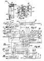
- the electronic circuitry is designated generally by the reference numeral 160 and is comprised of a base unit 161 and a head unit 162.
- the head unit is of light portable construction, containing the computation read-out and operator input and may be mounted on the anesthetist's trolley, as illustrated in Figure 17.
- the base unit does not require the operator or anesthetist to manipulate or otherwise interact with the components thereof and therefore may be positioned at floor level with other components, such as the vacuum module.
- the spectrometer Since the spectrometer requires potentials of approximately 100 volts, and is in close proximity to the patient, all the spectrometer electrical supply requirements are constructed as a ground isolated system, using isolating transformers and construction approved for this application. The purpose of such a ground isolated system is to insure that a leakage to ground via the patient, or otherwise, causes an unmeasurable flow of current, thus, protecting the patient from harm. In addition, active ground current monitoring from the isolated electronics will produce an immediate shut-down and notify the operator of fault conditions.
- fibre optic lines which not only provide ground isolation, but also eliminate the transmission of electro-magnetic interference to the head unit.
- one of the fibre optic lines 165 transmits information to change the frequency of the radio frequency energy applied to the spectrometer in order to tune ions of different mass.
- the outgoing fibre optic line 166 provides digitized information of the ion current at the spectrometer collector plate 135, the ion current collected by the ion collector wire 128, as well as monitoring the potential supplied to the spectrometer system in absence of fault conditions.
- the base unit 161 includes a D.C. power source 163 which is provided with a filament electrical current supply 164, which is controlled by the electron emission current received on the grid helix 120 of the ionization zone, and which stabilizes this emission current at a given value.
- the filament current supply 164 also senses for a voltage applied --no filament current flow situation, and if found switches over to the second filament.
- the head unit is notified of the switchover and flags the operator by a visual or audible signal.
- the head unit also senses and determines that current is flowing through both filaments and start-up is prevented if only one filament is operable.
- the current to the inactive filament will be supplied through a resistor until the additional filament is needed.
- the D.C. power unit 163 is also provided with a 100 volt electron acceleration current supply 168, which forms the feedback signal for the filament supply 167.
- a 120-volt supply current 169 serves to bias the pressure sensing ion collector wire 128. This current is isolated from the rest of the spectrometer and supplies zero volt bus so that the ion current flow can be sensed at bus potential and transmitted to the head unit 162.
- a 100-volt current supply 170 supplies the current to operate the linear accelerator 129.
- This current supply is modulated at audio frequency by a sinusoid of 1-2 volts amplitude.
- the final ion current in the ion collector plate is phase detected with the audio signal as a reference.
- the resultant output is used to vary the exact value of the 100-volt potential in order to maximize the ion current, that is, to have a minimum first harmonic component in the phase detected ion signal.
- This correction maintains the spectrometer 100 in tune, as well as compensating for dimensional tolerances in the spectrometer head and possible slump of the structure due to mistreatment.
- This seeking function is responsible for the maintenance of the spectrometer 100 in calibration without day-to-day adjustment by an operator.
- a programmable D.C. supply unit 171 has a 30-volt programmable current supply or conductor 172, which is controlled by input from the head unit 162.
- the current supply 172 sets the potential at which the ions are generated and, therefore, the acceleration that they must obtain in order to land on the grounded ion collector plate 135. The potential of this supply is also sensed by the head unit 162.
- the base unit 161 also includes a programmable radio frequency generator 173 whose radio frequency signal is transmitted to the spectrometer by two coaxial cables 174, each terminated by its iterative impedance.
- the radio frequency generator consists of a group of quartz crystal controlled oscillators, together with harmonic multipliers, and a wide band power amplifier capable of delivering a 5-volt peak amplitude radio frequency signal to the spectrometer. The output level is rectified and fed back to the power amplifier in order to keep the amplitude of the radio frequency amplitude constant. Switching between oscillators is performed on command by control means of the head unit 162 in order to select different ion species for analysis. In general, the switching rate between ion species will be determined by the settling time of the ion collection amplifier.
- the base unit 161 is also provided with an auxiliary thermistor and pressure transducer power unit 175 having a current supply conductor 176 and a current supply conductor 177 electrically connected with a pair of auxiliary thermistors, the function of which will be set forth more clearly hereinbelow.
- a pair of current supply conductors 178 also electrically connects the power unit 175 with a differential pressure transducer 179.
- Output signals from the differential pressure transducer 179 are transmitted to a multiplexor unit 180 via conductors 181.
- the multiplexor unit 180 is a component of a data acquisition system, which also includes a 10-bit analogical digital converter 182 and control electronics for transmitting the digitized information to the head unit 162.
- the multiplexor unit 180 as well as transmitting spectrometer ion current data, spectrometer pressure ion current data, and parameters of the spectrometer, also transmits data obtained from zener reference sources in order to check the continual functionality of the multiplexor-analog digital converter system.
- An ion current amplifier 183 is mounted as a head amplifier in the connection socket 184 of the mass spectrometer header 106 and is followed by a second amplifier (not shown) at the module end of the connecting cable for the connection socket.
- the use of a head amplifier eliminates the problems associated with a large cable capacitance which would otherwise be associated with a remote amplifier.
- the head unit 162 constitutes a system controller, which communicates with the spectrometer system through the fibre optic cables 165 and 166, as described hereinabove.
- the system controller actually constitutes a micro-computer 185 to serial input-output ports and can be fabricated from any of the commercial central processing units of desired capacity.
- the micro-computer or CPU has been duplicated for maximum reliability and for continuation of monitoring, should a run-wild or halt occur in the system. It is also pointed out that each CPU is provided with a watch dog set to detect malfunction.
- the system also includes a display and user interface 186, which may be a conventional screen-keyboard, a custom LCD panel, or a touch-sensitive input tablet.
- the head unit includes a digital analog converter 187, which can be operated from the incoming signal line from the head unit 162.
- the digital analog converter 187 is connected through one of the multiplexor unit channels to the analog digital converter 182. Start-up testing, therefore, programs a staircase wave form on the digital analog computer, with the analog digital converter 182 converting each step. This enables the monotonacity in the absence of missing codes to be checked by both the digital analog converter 187 and the analog digital converter 182. Under operating conditions, the digital analog converter 187 sets the levels of the power supply, which generates the starting potential of the ions.
- an output line to a central recording area where the spectrometer data can be continuously recorded in a tamper-resistant environment in order to provide information on the progress of the patient during surgery, and to have documentation available for future use, such as possible future litigation.
- the rotatable valve 63 in the manifold unit will be manipulated to a position for measuring the sample gases from the lower trachea or from the tracheal sampling cell 39. If the lung gases are being sampled, then the head unit of the apparatus will indicate that this function is being performed and that the tracheal sampling cell 39 is not in use.
- the cardiac output may be measured by a single breath method procedure or by a CO2 rebreathing method.
- the single breath method uses the respiratory exchange ratio taken during a prolonged expiration (10 seconds).
- a detailed discussion of the single breath method and the computations used therein are expressed in the article entitled, "Estimation of True Venous and Arterial PCO2 by Gas Analysis of a Single Breath", by T. S. Kim, et al., appearing in the Journal of Applied Physiology , 21(4): 1338-1344; 1966.
- the respiratory exchange ratio taken during a prolonged expiration (10 seconds) is expressed as follows:
- the mass spectrometer R produces data which is continuously calculated during a prolonged expiration, giving rise to a curve.
- the slope (S) of the tangents at various intervals is used to derive a family of instantaneous R values from the following form of the alveolar air equation: Solving for R:
- the various instantaneous values of R are then plotted against their corresponding measured PCO2 (arterial-alveolar). This allows the estimation of the appropriate arterial and mixed venous CO2 tensions that must have existed.
- the arterial PCO2 is obtained from the R value averaged from several normal expired breaths preceding a greater than normal inspiration followed by a prolonged expiration (10 seconds).
- the key to this single breath method is the ability to determine PO2 and PCO2 at the same instant in time which is made possible by the miniature mass spectrometer attached to the upper end of the endotracheal tube or mouthpiece device, thereby eliminating a maximum amount of dead space.
- the correlation of this data with heart rate is critical in the single breath method.
- this method is also simple and is carried out in less than 30 seconds. Specifically, this method depends on assessing the time it takes for rebreathed CO2 to reach a plateau. The precise detail of this method is described in an article entitled, "Cardiac Output Determination by Simple One-Step Rebreathing Technique" by L. E. Farhi et al., published in Respiration Physiology (1976), 28, 141-159. However, the present apparatus obviously increases the accuracy and shortens the time needed to reach a plateau because the dead space is reduced.
- Heart beat correlation with the CO2 rebreathing method is important, but not as cirtical as with the single breath method. It is pointed out that, during the single breath method and the CO2 rebreathing method, the lung gases are circulated through the sample gas passage 20 in the endotracheal tube and are returned through the return passage 19. If the mouthpiece device 143 is used, the sample gases are directed upwardly through the sample gas passage 148 and are returned through the return passage 149.
- the lung capacity or volume is determined by the differential pressure transducer and receives gas samples from below and above the capillary restriction member 27 in the endotracheal tube or the capillary restriction member 154 in the disposable mouthpiece device.
- the location of the restriction capillary member 27 in the endotracheal tube or the capillary restriction member 154 in the mouthpiece device is chosen so that the temperature of the capillaries will be close to body temperature, thus eliminating condensation of moisture within the capillaries. Flow of gases through these capillaries produces a pressure differential which is communicated through their associated passages to the differential pressure transducer for measuring respiratory volume.
- both of the balloons 33 are inflated and serve as retention members during sampling of lung gases by means of the endotracheal tube, these balloons also define the tracheal sampling cell for use in making an analysis of the tissue cell gases. Sampling from this tracheal sampling space is undertaken when it equilibrates with the tracheal tissue and will measure tracheal tissue O2 (and CO2), which will closely reflect arterial PO2. This sample gas will be representative of tissue PO2 in other parts of the body and, therefore, indicate the accuracy of oxygenation. This particular procedure should reduce or entirely eliminate the need for arterial samples, thereby making effective arterial PO2 determination a non-invasive procedure of choice.
- Sampling from the tracheal sampling cells 39 is done by flushing argon gas through the openings or ports which communicate with the tracheal sampling cell and circulating the argon gas through the mass spectrometer for analysis until the argon gas reaches an equilibrium condition in the tracheal sampling cell.
- a tracer amount of gas such as acetylene
- the lung to trachea circulation time can be measured. This is a useful physiological measurement to assess the efficiency of blood circulation.
- the uptake kinetics of acetylene can be used to assess local blood flow in tracheal tissues.
- the apparatus can measure other aspects of respiratory functions.
- the apparatus can measure the anatomic respiratory dead space, the physiological respiratory dead space, the pulmonary diffusing capacity for O2 and CO2, and the anatomic and physiological shunt flow.
- two thermistors are placed in the sampling gas stream.
- One of the thermistors is placed upstream of the circulator gears of the pump, and one is placed downstream of the circulator gears of the pump.
- the upstream thermistor will be used to correct the respired air volumes to standard temperature, while the downstream thermistor is supplied with sufficient electrical energy to self-heat it to a few degrees above the ambient temperature.
- the flow of electrical energy to this downstream thermistor is interrupted and its cooling rate measured. The cooling rate will indicate that there is a continuous flow of gases around the measuring loop.
- the sample gas passage or the return passage is blocked, or if, for any reason, the circulator gears do not rotate, the abnormal cooling rate of the downstream thermistor will make the instrument operator aware of this malfunction.
- the positioning of thermistors on opposite sides of the pump gears provides thermal isolation between them.
- the novel gas sampling apparatus can provide a non-invasive means for accurately and routinely monitoring cardiac output and the cardio-respiratory function in conscious, as well as anesthetized or unconscious, human subjects. Since the endotracheal tube and mouthpiece are disposable, the motor pump and mass spectrometer module may be readily disconnected therefrom and reused after centrifuging. The gas sampling efficiency of the apparatus, especially the endotracheal tube, is greatly enhanced by the elimination of dead space. The provision of a miniature motor pump - mass spectrometer module allows this efficiency to be obtained. Miniature mass spectrometers having a free mean path of the order of one-half to two centimenters in length are simply unknown in medical and related fields.
Landscapes
- Health & Medical Sciences (AREA)
- Life Sciences & Earth Sciences (AREA)
- Pulmonology (AREA)
- Veterinary Medicine (AREA)
- Biomedical Technology (AREA)
- Heart & Thoracic Surgery (AREA)
- Engineering & Computer Science (AREA)
- Animal Behavior & Ethology (AREA)
- General Health & Medical Sciences (AREA)
- Public Health (AREA)
- Cardiology (AREA)
- Hematology (AREA)
- Physiology (AREA)
- Physics & Mathematics (AREA)
- Biophysics (AREA)
- Pathology (AREA)
- Medical Informatics (AREA)
- Molecular Biology (AREA)
- Surgery (AREA)
- Emergency Medicine (AREA)
- Anesthesiology (AREA)
- Otolaryngology (AREA)
- Other Investigation Or Analysis Of Materials By Electrical Means (AREA)
- Measurement Of The Respiration, Hearing Ability, Form, And Blood Characteristics Of Living Organisms (AREA)
- Electron Tubes For Measurement (AREA)
Claims (13)
- Gasprobensammelvorrichtung (11; 143) zum Sammeln von Atemgasproben von einer menschlichen Person, welche Vorrichtung (11; 143) eine Röhre zur Einführung in den Mund dieser menschlichen Person umfaßt, wobei die Röhre ein oberes Ende, das mit Mitteln (18) zum Anschließen der Vorrichtung (11; 143) an ein Gerät zur Analyse der gesammelten Gase versehen ist, und ein unteres Ende aufweist;
dadurch gekennzeichnet, daß die Röhre über ihre gesamte Länge von doppelwandiger Konstruktion ist und innere und äußere röhrenförmige Elemente (13, 14; 145, 146) umfaßt, wobei das Innere des inneren röhrenförmigen Elements (13; 145) einen durch dieses hindurchführenden zentralen Kanal (15) definiert, sowie Mittel (16), die den Raum zwischen dem inneren und dem äußeren Element (13, 14; 145, 146) in eine Mehrzahl länglicher peripherer Kanäle (19 bis 26; 148, 149) unterteilen, welche sich über die gesamte Länge der doppelwandigen Röhre erstrecken, und eine Mehrzahl von Öffnungen (29 bis 32, 37, 40, 41; 150, 151, 157, 158) in einem unteren Endabschnitt des inneren röhrenförmigen Elements (13; 145) umfaßt, wobei jede Öffnung (29 bis 32, 37, 40, 41; 150, 151, 157, 158) mit den jeweiligen Kanälen (19 bis 26; 148, 149) in Verbindung steht, und weiters dadurch, daß die genannte Vorrichtung (11; 143) außerdem ein kapillares Beschränkungselement (27; 154) enthält, das in dem zentralen Kanal (15) angeordnet ist, welches Element (27; 154) eine Mehrzahl von darin befindlichen kapillaren Öffnungen (28; 155) aufweist, um den Luftstrom durch diesen zentralen Kanal (15) zu beschränken. - Gasprobensammelvorrichtung (11; 143) nach Anspruch 1, worin die länglichen peripheren Kanäle (19 bis 26; 148, 149) einen Gasprobensammelkanal (20; 148), mit dem eine (30; 150) der genannten Öffnungen (29 bis 32, 37, 40, 41; 150, 151, 157, 158) in Verbindung steht, um es Lungengasen zu ermöglichen, ausgehend von dem zentralen Kanal (15) den Gasprobensammelkanal (20; 148) entlang nach oben zu strömen, einen Rückführkanal (19; 149), mit dem eine andere (29; 151) der Öffnungen (29 bis 32, 37, 40, 41; 150, 151, 157, 158) in Verbindung steht und durch welchen Lungengase zurückgeführt werden, und ein Paar von Druckmeßkanälen (21, 23) umfassen, mit denen jeweilige weitere (31, 32; 157, 158) der Öffnungen (29 bis 32, 37, 40, 41; 150, 151, 157, 158) in Verbindung stehen, wobei eine derartige Druckmeßöffnung (32; 157) unter dem kapillaren Beschränkungselement (27; 154) angeordnet ist und sich die andere derartige Druckmeßöffnung (31; 158) angrenzend an, jedoch über diesem kapillaren Beschränkungselement (27; 154) befindet.
- Gasprobensammelvorrichtung (11; 143) nach Anspruch 1 oder 2, die eine längliche endotracheale Röhre (11) bildet, die sich im Zustand der Verwendung bis in die untere Luftröhre der menschlichen Person hinunter erstreckt.
- Gasprobensammelvorrichtung (11; 143) nach Anspruch 1 oder 2, die ein Mundstück (143) mit einem unteren Ende bildet, das im Zustand der Verwendung in der Mundhöhle der menschlichen Person endet.
- Gasprobensammelvorrichtung (11; 143) nach Anspruch 3, in Kombination mit einem Paar von aufblasbaren Ballonelementen (33), die an dem äußeren röhrenförmigen Element (14; 146) befestigt sind und entlang diesem in einem Abstand voneinander angeordnet sind, worin die genannte Mehrzahl von länglichen peripheren Kanälen (19 bis 26; 148, 149) umfaßt:
einen länglichen Aufblaskanal (22), wobei es ein Paar von Aufblasöffnungen (37) gibt, die so in dem äußeren röhrenförmigen Element (14; 146) ausgebildet sind, daß die Ballonelemente (33) und der längliche Aufblaskanal (22) miteinander in Verbindung stehen, um ein Auflasen der Ballonelemente (33) sowie ein Luftablassen aus denselben zu ermöglichen, welche Ballonelemente (33) im aufgeblasenen Zustand mit der inneren Oberfläche der Luftröhre der menschlichen Person in Eingriff sind und mit dieser zusammenwirken, um eine ringförmige tracheale Probensammelzelle (39) zu bilden; und
einen trachealen Probensammelkanal (24) und einen trachealen Rückführkanal (25), wobei es eine tracheale Probensammelöffnung (40) und eine tracheale Rückführöffnung (41) gibt, die so in dem äußeren röhrenförmigen Element (14; 146) ausgebildet sind, daß der tracheale Probensammelkanal (24) und der tracheale Rückfuhrkanal (25) mit der trachealen Probensammelzelle (39) in Verbindung stehen, um eine Analyse trachealer Gewebsgase zu ermöglichen. - Gasprobensammelvorrichtung (11; 143) nach irgendeinem der vorhergehenden Ansprüche, worin die Vorrichtung zum einmaligen Gebrauch bestimmt ist.
- Gerät (10) zum Sammeln und Analysieren von Atemgasproben von einer menschlichen Person, umfassend eine Gasprobensammelvorrichtung zum Einführen in den Mund einer menschlichen Person, um solche Atemgasproben zu sammeln, wobei die Gasprobensammelvorrichtung eine Vorrichtung (11; 143) nach irgendeinem der Ansprüche 1 bis 6 umfaßt, einen Miniaturmotorpumpen-Massenspektrometermodul (12), der ein Massenspektrometer (100) enthält, Mittel, welche das Massenspektrometer (100) mit einer Vakuumquelle verbinden, einen Differenzdruckmeßwandler, Verbindungsmittel, durch welche Proben der Atemgase von der Gasprobensammelvorrichtung (11; 143) zu dem Massenspektrometer (100) und/oder zu dem Differenzdruckmeßwandler geleitet werden, und elektronische Schaltungen (160), die mit dem Massenspektrometer (100) und dem Druckmeßwandler zusammenwirken, um die Lungengase und die Lungenkapazität der menschlichen Person zu analysieren.
- Gerät (10) nach Anspruch 7, worin der genannte Motorpumpen-Massenspektrometermodul (12) eine Motorpumpeneinheit (71) einschließt, die ein Motorpumpengehäuse (72), das einen Auslaß (111) aufweist, welcher mit dem Massenspektrometer (100) in Verbindung steht, eine nichtmagnetische Trennwand (73), welche das Innere des Motorpumpengehäuses (72) in eine Motorkammer (74) und eine Pumpkammer (75) unterteilt, ein Paar von drehbaren ineinandergreifenden Zahnrädern (86) in der Motorkammer (74) und ein Paar von drehbaren ineinandergreifenden Zahnrädern (93) in der Pumpkammer (75), wobei jedes Zahnrad in der einen Kammer (74, 75) mit einem Zahnrad in der anderen Kammer (74, 75) koaxial angeordnet ist, magnetische Elemente auf dem Zahnrad in der Motorkammer (74) und auf dem koaxial angeordneten Zahnrad in der Pumpkammer (75), welche zusammenwirken, wobei ein Paar der Kanäle (19 bis 26; 145, 146) der Gasprobensammelvorrichtung (11; 143) mit der Pumpkammer (75) in kommunizierender Weise verbunden ist, sowie Mittel (82) umfaßt, welche die Motorkammer (74) mit einer Druckluftquelle verbinden, um die Motorkammerzahnräder anzutreiben und dadurch die Pumpkammerzahnräder anzutreiben, die dazu dienen, die gesammelten Gasproben in das Massenspektrometer (100) zu leiten.
- Gerät (10) nach Anspruch 7 oder 8, worin das Massenspektrometer (100) umfaßt:
ein Gehäuse (101) mit einer Einlaßpforte (109), durch welche zu analysierende Gasproben geleitet werden, wobei das Gehäuse (101) eine darin befindliche Öffnung (140) aufweist, Mittel, welche die Öffnung (140) in dem Gehäuse (101) mit einer Vakuumquelle verbinden, damit der Druck innerhalb des Spektrometergehäuses (101) bei 10E⁻³ Torr gehalten werden kann; einen Ionengenerator, der so in diesem Gehäuse (101) vorgesehen ist, daß er in einem Abstand von, jedoch neben dessen Einlaßpforte (109) angeordnet ist, und der eine Gitterwendel (120) einschließt, die an eine elektrische Energiequelle angeschlossen ist, wobei das Innere dieser Gitterwendel (120) eine Ionisationszone definiert; einen Elektronenemissionsfaden (125), der in dem Gehäuse (101) vorgesehen ist und an eine elektrische Stromquelle angeschlossen ist, wobei dieser Emissionsfaden (125) bei Erregung Elektronen in Richtung auf die Gitterwendel (120) emittiert und beschleunigt, um Gasprobenmoleküle in der Ionisationszone zu fragmentieren und zu ionisieren; einen Linearbeschleuniger (129), der innerhalb des Gehäuses (101) neben dem genannten Generator angeordnet ist und eine Vielzahl von gleichmäßig beabstandeten Beschleunigungselektrodenplatten (130) umfaßt, die jeweils eine zentrale Öffnung (134) aufweisen, wobei diese Öffnungen (134) in den Beschleunigungselektrodenplatten (130) axial in einer Reihe angeordnet sind und eine axiale Beschleunigungsstrecke definieren; eine Ionenkollektorplatte (135), die in dem Gehäuse (101) neben, jedoch in einem Abstand von der stromabwärtigen Beschleunigungselektrodenplatte (130) des Linearbeschleunigers (129) angeordnet ist; Mittel (133, 133a), welche den Linearbeschleuniger (129) mit einer elektrischen Strom- und Hochfrequenzquelle verbinden, deren Potential sich von dem elektrischen Potential des Ionengenerators unterscheidet, wodurch Ionen in Richtung auf den Linearbeschleuniger (129) vorgespannt werden und durch die Öffnungen (134) in den Beschleunigungselektrodenplatten (130) hindurch in Richtung auf die Kollektorplatte (135) zunehmend beschleunigt werden, so daß hierdurch ein Ionenstrom erzeugt wird; wobei die freie Weglänge des Spektrometers (100) von der Einlaßpforte (109) bis zu der Ionenkollektorplatte (135) in der Größenordnung von etwa einem halben Zentimeter bis zwei Zentimetern liegt. - Gerät (10) nach Anspruch 9, worin die Beschleunigungselektrodenplatten (130) des Linearbeschleunigers (129) von dreieckiger Konfiguration sind, wobei die Mittel (133, 133a), welche die Beschleunigungselektrodenplatten (130) mit einer elektrischen Stromquelle verbinden, ein Paar von Busschienen (133, 133a) umfassen, die jeweils mit alternierenden Elektrodenplatten (130) verbunden sind, um ein vorspannendes elektrisches Potential in dem Zwischenraum zwischen benachbarten Platten (130) zu schaffen.
- Gerät (10) nach Anspruch 10, worin die genannten Busschienen (133, 133a) elektrisch an einen Hochfrequenzgenerator angeschlossen sind, der dafür verwendet werden kann, die Schienen (133, 133a) mit einer Hochfrequenzspannung mit einem Spitzenwert von etwa 5 Volt zu überlagern.
- Gerät (10) nach Anspruch 9, 10 oder 11, das außerdem eine Ionensammelfalle (127) umfaßt, die in dem Spektrometergehäuse (101) in bezug auf den Elektronenemissionsfaden (125) gegenüberliegend angeordnet ist, wobei diese Ionensammelfalle (127) mit einer elektrischen Stromquelle verbunden ist und während des Betriebs des Massenspektrometers (100) dafür verwendet werden kann, den Gasdruck in dem Spektrometergehäuse (101) zu überwachen.
- Gerät (10) nach irgendeinem der Ansprüche 9 bis 12, worin der Ionengenerator eine Eingangselektrodenplatte (117), die eine darin befindliche Öffnung (118) aufweist und neben der Einlaßpforte (109) des Spektrometergehäuses (101) angeordnet ist, wobei diese Eingangselektrodenplatte (117) mit der Gitterwendel (120) verbunden ist, sowie eine Absaugelektrodenplatte (122) umfaßt, die eine darin befindliche Öffnung (123) aufweist und zwischen der Gitterwendel (120) und dem Linearbeschleuniger (129) angeordnet ist, wobei diese Absaugelektrodenplatte (122) mit einer elektrischen Stromquelle verbunden ist und ein elektrisches Potential aufweist, das sich von dem der Gitterwendel (120) und des Linearbeschleunigers (129) unterscheidet, und dazu dient, ein von der Ionisationszone in Richtung auf die Ionenkollektorplatte (135) vorgespanntes Ion zu beschleunigen.
Applications Claiming Priority (2)
| Application Number | Priority Date | Filing Date | Title |
|---|---|---|---|
| US07/205,668 US4850371A (en) | 1988-06-13 | 1988-06-13 | Novel endotracheal tube and mass spectrometer |
| US205668 | 1988-06-13 |
Publications (3)
| Publication Number | Publication Date |
|---|---|
| EP0347101A2 EP0347101A2 (de) | 1989-12-20 |
| EP0347101A3 EP0347101A3 (de) | 1991-04-17 |
| EP0347101B1 true EP0347101B1 (de) | 1995-07-26 |
Family
ID=22763150
Family Applications (1)
| Application Number | Title | Priority Date | Filing Date |
|---|---|---|---|
| EP89305793A Expired - Lifetime EP0347101B1 (de) | 1988-06-13 | 1989-06-08 | Endotriachealröhre und Massenspektrometer |
Country Status (7)
| Country | Link |
|---|---|
| US (1) | US4850371A (de) |
| EP (1) | EP0347101B1 (de) |
| JP (2) | JPH0624529B2 (de) |
| KR (1) | KR950000056B1 (de) |
| CA (1) | CA1311566C (de) |
| DE (1) | DE68923586T2 (de) |
| TW (1) | TW199093B (de) |
Cited By (1)
| Publication number | Priority date | Publication date | Assignee | Title |
|---|---|---|---|---|
| US7654264B2 (en) | 2006-07-18 | 2010-02-02 | Nellcor Puritan Bennett Llc | Medical tube including an inflatable cuff having a notched collar |
Families Citing this family (120)
| Publication number | Priority date | Publication date | Assignee | Title |
|---|---|---|---|---|
| US5024218A (en) * | 1987-10-21 | 1991-06-18 | The Kendall Company | Intubating airway |
| US4966141A (en) * | 1988-06-13 | 1990-10-30 | Bacaner Marvin B | Endotracheal tube and mass spectrometer |
| NL8900800A (nl) * | 1989-03-31 | 1990-10-16 | Mijnhardt Bv | Werkwijze en inrichting voor het kontinu analyseren van de samenstelling van gassen. |
| USH962H (en) | 1989-08-29 | 1991-09-03 | United States Of America | Automated stability/compatibility apparatus |
| US5042501A (en) * | 1990-05-01 | 1991-08-27 | Battelle Memorial Institute | Apparatus and method for analysis of expired breath |
| US5136161A (en) * | 1990-12-03 | 1992-08-04 | Spacelabs, Inc. | Rf mass spectrometer |
| US5285778A (en) * | 1991-04-19 | 1994-02-15 | Mackin Robert A | Endotracheal tube wih fibers optic illumination and viewing and auxiliary tube |
| US5205281A (en) * | 1991-08-02 | 1993-04-27 | Buchanan Dale C | Oral airway with oximetry means |
| US5174284A (en) * | 1991-09-05 | 1992-12-29 | G.I. Supply, Inc. | Endoscopic bite block |
| US5291882A (en) * | 1992-05-11 | 1994-03-08 | Makhoul Imad R | Multi-lumen ITPV endotracheal tube |
| DE4221931C1 (de) * | 1992-07-03 | 1993-07-08 | Harald Dr. 8521 Moehrendorf De Mang | |
| US5810741A (en) * | 1992-11-05 | 1998-09-22 | Synectics Medical Ab | Method of measuring respiration and respiratory effort using plural catheters |
| US5477860A (en) * | 1992-11-05 | 1995-12-26 | Synectics Medical, Inc. | Catheter for measuring respiration and respiratory effort |
| USD348932S (en) | 1992-11-23 | 1994-07-19 | Chek-Med Systems, Inc. | Combined bite block and cusps |
| US5438985A (en) * | 1993-01-25 | 1995-08-08 | Synectics Medical, Incorporated | Ambulatory recording of the presence and activity of substances in gastro-intestinal compartments |
| US6758217B1 (en) * | 1993-02-05 | 2004-07-06 | University Of Manitoba | Control of airway pressure during mechanical ventilation |
| US5657759A (en) * | 1993-05-13 | 1997-08-19 | Synectics Medical, Incorporated | Measurement of gastric emptying and gastrointestinal output |
| US5551425A (en) * | 1993-05-13 | 1996-09-03 | Synectics Medical, Inc. | Potential difference and perfusion pressure catheter |
| DE4318690A1 (de) * | 1993-06-04 | 1995-01-05 | Ndd Medizintechnik Gmbh | Verfahren zur Messung der Molmasse von Gasen oder Gasgemischen und Vorrichtung zur Durchführung dieses Verfahrens |
| US5515859A (en) * | 1993-08-24 | 1996-05-14 | Colorado Health Care Research Corp. | Myocardial infarction and ischemia detection method and apparatus |
| US5507289A (en) * | 1993-09-16 | 1996-04-16 | Synectics Medical, Inc. | System and method to diagnose bacterial growth |
| US5477854A (en) * | 1993-09-16 | 1995-12-26 | Synectics Medical, Inc. | System and method to monitor gastrointestinal Helicobacter pylori infection |
| US5386115A (en) * | 1993-09-22 | 1995-01-31 | Westinghouse Electric Corporation | Solid state micro-machined mass spectrograph universal gas detection sensor |
| US5507284A (en) * | 1993-09-27 | 1996-04-16 | Daneshvar; Yousef | Airway securing system |
| US5833625A (en) * | 1993-10-21 | 1998-11-10 | Synectics Medical Ab | Ambulatory reflux monitoring system |
| US5479935A (en) * | 1993-10-21 | 1996-01-02 | Synectics Medical, Inc. | Ambulatory reflux monitoring system |
| US5401963A (en) * | 1993-11-01 | 1995-03-28 | Rosemount Analytical Inc. | Micromachined mass spectrometer |
| US5479815A (en) * | 1994-02-24 | 1996-01-02 | Kraft Foods, Inc. | Method and apparatus for measuring volatiles released from food products |
| US6729334B1 (en) * | 1994-06-17 | 2004-05-04 | Trudell Medical Limited | Nebulizing catheter system and methods of use and manufacture |
| US5590651A (en) * | 1995-01-17 | 1997-01-07 | Temple University - Of The Commonwealth System Of Higher Education | Breathable liquid elimination analysis |
| DE19504382A1 (de) * | 1995-02-10 | 1996-08-14 | Mann & Hummel Filter | Ansaugsystem |
| US5544648A (en) * | 1995-05-12 | 1996-08-13 | Cook Incorporated | Device for intratracheal ventilation and intratracheal pulmonary ventilation including reverse venturi |
| US5638813A (en) * | 1995-06-07 | 1997-06-17 | Augustine Medical, Inc. | Tracheal tube with self-supporting tracheal tube cuff |
| US5660175A (en) * | 1995-08-21 | 1997-08-26 | Dayal; Bimal | Endotracheal device |
| US20010044588A1 (en) * | 1996-02-22 | 2001-11-22 | Mault James R. | Monitoring system |
| JP3922739B2 (ja) * | 1996-04-26 | 2007-05-30 | 積水化学工業株式会社 | 気管切開カテーテル |
| US6309360B1 (en) | 1997-03-17 | 2001-10-30 | James R. Mault | Respiratory calorimeter |
| SE9703291L (sv) * | 1997-09-11 | 1998-10-05 | Siemens Elema Ab | Inspirationsslang |
| US5957134A (en) * | 1997-11-18 | 1999-09-28 | Lee; Han Shik | Anesthesia delivery system |
| US6572561B2 (en) | 1998-01-16 | 2003-06-03 | Healthetech, Inc. | Respiratory calorimeter |
| JP2002501806A (ja) | 1998-02-05 | 2002-01-22 | ジェームズ アール モールト | 呼吸ガス分析を用いた代謝熱量測定装置 |
| US6196222B1 (en) * | 1998-03-10 | 2001-03-06 | Instrumentarium Corporation | Tracheal gas insufflation delivery system for respiration equipment |
| AUPP229498A0 (en) * | 1998-03-11 | 1998-04-09 | Oldfield Family Holdings Pty Limited | Endotracheal tube for selective bronchial occlusion |
| CA2338998A1 (en) | 1998-08-03 | 2000-02-17 | James R. Mault | Method and apparatus for respiratory gas analysis employing measurement of expired gas mass |
| US6135111A (en) * | 1998-08-31 | 2000-10-24 | Vital Signs Inc. | Tracheostomy tube with removable inner cannula |
| SE512807C2 (sv) * | 1998-09-02 | 2000-05-15 | Bjoern Flodin | Anordning för tillförsel av inandningsgas till och bortförsel av utandningsgas från en patient |
| US6406435B1 (en) | 1998-11-17 | 2002-06-18 | James R. Mault | Method and apparatus for the non-invasive determination of cardiac output |
| US6431170B1 (en) * | 1999-01-28 | 2002-08-13 | Respironics, Inc. | Fluid mixing apparatus, method and system using same |
| US6071237A (en) * | 1999-02-19 | 2000-06-06 | Institute Of Critical Care Medicine | Device and method for assessing perfusion failure in a patient during endotracheal intubation |
| JP2003527881A (ja) | 1999-05-10 | 2003-09-24 | ジェームズ アール モールト | 気道ベース心臓血液搏出量モニタおよび該モニタの使用方法 |
| US6287290B1 (en) * | 1999-07-02 | 2001-09-11 | Pulmonx | Methods, systems, and kits for lung volume reduction |
| US6899684B2 (en) * | 1999-08-02 | 2005-05-31 | Healthetech, Inc. | Method of respiratory gas analysis using a metabolic calorimeter |
| US6468222B1 (en) | 1999-08-02 | 2002-10-22 | Healthetech, Inc. | Metabolic calorimeter employing respiratory gas analysis |
| WO2001028416A1 (en) | 1999-09-24 | 2001-04-26 | Healthetech, Inc. | Physiological monitor and associated computation, display and communication unit |
| CA2387124A1 (en) | 1999-10-08 | 2001-04-26 | Healthetech, Inc. | Integrated calorie management system |
| US6612306B1 (en) | 1999-10-13 | 2003-09-02 | Healthetech, Inc. | Respiratory nitric oxide meter |
| US6629934B2 (en) | 2000-02-02 | 2003-10-07 | Healthetech, Inc. | Indirect calorimeter for medical applications |
| US6482158B2 (en) | 2000-05-19 | 2002-11-19 | Healthetech, Inc. | System and method of ultrasonic mammography |
| US20030208110A1 (en) * | 2000-05-25 | 2003-11-06 | Mault James R | Physiological monitoring using wrist-mounted device |
| WO2001093743A2 (en) * | 2000-06-07 | 2001-12-13 | Healthetech, Inc. | Breath ketone analyzer |
| JP2004503887A (ja) * | 2000-06-16 | 2004-02-05 | ヘルセテック インコーポレイテッド | 携帯情報端末用音声認識装置 |
| AU2001296456A1 (en) | 2000-09-29 | 2002-04-08 | Healthetech, Inc. | Indirect calorimetry system |
| US20060135947A1 (en) | 2000-10-27 | 2006-06-22 | Pulmonx | Occlusal stent and methods for its use |
| US6527761B1 (en) * | 2000-10-27 | 2003-03-04 | Pulmonx, Inc. | Methods and devices for obstructing and aspirating lung tissue segments |
| US6607387B2 (en) | 2000-10-30 | 2003-08-19 | Healthetech, Inc. | Sensor system for diagnosing dental conditions |
| AU2002250237A1 (en) * | 2001-03-02 | 2002-09-19 | Healthetech, Inc. | A system and method of metabolic rate measurement |
| IL142228A (en) * | 2001-03-23 | 2006-12-31 | Hospitec Inc | Method and system for intubation |
| US20030023181A1 (en) * | 2001-07-26 | 2003-01-30 | Mault James R. | Gas analyzer of the fluorescent-film type particularly useful for respiratory analysis |
| US20030130595A1 (en) * | 2001-08-13 | 2003-07-10 | Mault James R. | Health improvement systems and methods |
| US20030130567A1 (en) * | 2002-01-09 | 2003-07-10 | Mault James R. | Health-related devices and methods |
| US20030051733A1 (en) * | 2001-09-10 | 2003-03-20 | Pulmonx | Method and apparatus for endobronchial diagnosis |
| US7883471B2 (en) | 2001-09-10 | 2011-02-08 | Pulmonx Corporation | Minimally invasive determination of collateral ventilation in lungs |
| US20030073918A1 (en) * | 2001-10-15 | 2003-04-17 | Orr Joseph A. | Configuration-retaining conduit for use in obtaining metabolic measurements from respiration |
| US20030105407A1 (en) * | 2001-11-30 | 2003-06-05 | Pearce, Edwin M. | Disposable flow tube for respiratory gas analysis |
| US20030152607A1 (en) * | 2002-02-13 | 2003-08-14 | Mault James R. | Caloric management system and method with voice recognition |
| US7291114B2 (en) * | 2002-04-01 | 2007-11-06 | Microlife Corporation | System and method of determining an individualized drug administration protocol |
| US7621879B2 (en) * | 2002-05-14 | 2009-11-24 | Pacesetter, Inc. | System for calibrating implanted sensors |
| US7862513B2 (en) * | 2002-05-14 | 2011-01-04 | Pacesetter, Inc. | Apparatus for minimally invasive calibration of implanted pressure transducers |
| US7258120B2 (en) * | 2002-05-29 | 2007-08-21 | University Of Florida Research Foundation, Inc. | Endotracheal tube apparatus and method for using the same to reduce the risk of infections |
| US20030226566A1 (en) * | 2002-06-06 | 2003-12-11 | Dhuper Sunil Kumar | Endotracheal tube with aerosol delivery apparatus II |
| USD478660S1 (en) | 2002-07-01 | 2003-08-19 | Healthetech, Inc. | Disposable mask with sanitation insert for a respiratory analyzer |
| US7470898B2 (en) | 2003-04-01 | 2008-12-30 | The Charles Stark Draper Laboratory, Inc. | Monitoring drinking water quality using differential mobility spectrometry |
| US20050085740A1 (en) * | 2003-04-01 | 2005-04-21 | Davis Cristina E. | Non-invasive breath analysis using field asymmetric ion mobility spectrometry |
| US7128071B2 (en) * | 2003-09-10 | 2006-10-31 | Indian Ocean Medical Inc. | Intubating laryngeal mask airway device with fiber optic assembly |
| US20050165456A1 (en) * | 2003-12-19 | 2005-07-28 | Brian Mann | Digital electrode for cardiac rhythm management |
| US7073503B2 (en) * | 2004-06-11 | 2006-07-11 | Vagn Niels Finsen Lomholt | Respiration catheter with sealing cuff and gas inflation cut-off valve |
| US20060162731A1 (en) | 2004-11-16 | 2006-07-27 | Pulmonx | Pulmonary occlusal stent delivery catheter, loading system and methods of use |
| US20060149330A1 (en) * | 2004-12-30 | 2006-07-06 | Brian Mann | Digitally controlled cardiac rhythm management |
| US20080228137A1 (en) | 2007-03-12 | 2008-09-18 | Pulmonx | Methods and devices for passive residual lung volume reduction and functional lung volume expansion |
| US11883029B2 (en) | 2005-01-20 | 2024-01-30 | Pulmonx Corporation | Methods and devices for passive residual lung volume reduction and functional lung volume expansion |
| US8496006B2 (en) | 2005-01-20 | 2013-07-30 | Pulmonx Corporation | Methods and devices for passive residual lung volume reduction and functional lung volume expansion |
| US8876791B2 (en) | 2005-02-25 | 2014-11-04 | Pulmonx Corporation | Collateral pathway treatment using agent entrained by aspiration flow current |
| US8721561B2 (en) * | 2005-05-10 | 2014-05-13 | Nspire Health, Inc. | Method and apparatus for analyzing pulmonary performance |
| US20070142742A1 (en) * | 2005-07-13 | 2007-06-21 | Pulmonx | Methods and systems for segmental lung diagnostics |
| NZ566767A (en) * | 2005-08-24 | 2011-03-31 | Hospitech Respiration Ltd | Intubating system where in an identifiable additive is introduced and measured to determine leak |
| CA2631516A1 (en) * | 2005-12-05 | 2007-06-14 | Hospitech Respiration Ltd. | Endotracheal tube and intubation system including same |
| US8523782B2 (en) | 2005-12-07 | 2013-09-03 | Pulmonx Corporation | Minimally invasive determination of collateral ventilation in lungs |
| RU2309668C1 (ru) * | 2006-02-20 | 2007-11-10 | Александр Сергеевич Парфенов | Способ неинвазивного определения функции эндотелия и устройство для его осуществления |
| US20080221582A1 (en) * | 2007-03-05 | 2008-09-11 | Pulmonx | Pulmonary stent removal device |
| US8100959B2 (en) * | 2007-03-09 | 2012-01-24 | Pulmonx Corporation | Loading device for a pulmonary implant |
| KR100946436B1 (ko) * | 2007-09-04 | 2010-03-10 | 김성수 | 날숨을 이용한 질병 조기진단 장치 및 방법 |
| US7963929B2 (en) * | 2007-09-21 | 2011-06-21 | Dtherapeutics, Llc | Devices and systems for sizing of a gastric pouch |
| US20100036361A1 (en) * | 2008-06-20 | 2010-02-11 | Pulmonx | System and method for delivering multiple implants into lung passageways |
| JP5848608B2 (ja) * | 2008-12-01 | 2016-01-27 | トリコーンテク コーポレーションTricornTech Corporation | 喘息、結核及び肺癌の診断及び疾患管理のための呼気分析システム及び方法 |
| WO2010091440A2 (en) * | 2009-01-20 | 2010-08-12 | Samir Bhatt | Airway management devices, endoscopic conduits, surgical kits, and methods using the same |
| US8057400B2 (en) | 2009-05-12 | 2011-11-15 | Angiologix, Inc. | System and method of measuring changes in arterial volume of a limb segment |
| US8596277B2 (en) * | 2009-06-18 | 2013-12-03 | Covidien Lp | Tracheal tube with lumen for tracheal pressure measurement and technique for using the same |
| KR101109700B1 (ko) * | 2009-09-07 | 2012-01-31 | 신경민 | 기도용 풍선 카데터 |
| FR2963740B1 (fr) * | 2010-08-12 | 2012-08-17 | Georges Boussignac | Systeme d'assistance respiratoire |
| CN102539513A (zh) * | 2010-12-09 | 2012-07-04 | 苏州生物医学工程技术研究所 | 一种用于患者疾病的无创检测装置及其检测方法 |
| US9498592B2 (en) | 2012-01-23 | 2016-11-22 | Aeon Research And Technology, Inc. | Modular pulmonary treatment system |
| CA2871175C (en) * | 2012-04-24 | 2019-07-02 | Panasonic Healthcare Co., Ltd. | Handle device and breath analysis device |
| US9121836B2 (en) * | 2012-05-29 | 2015-09-01 | Givaudan S.A. | Retronasal device and method |
| US20140014095A1 (en) * | 2012-07-11 | 2014-01-16 | Nellcor Puritan Bennett Llc | Tracheal tube with inner cannula indication system |
| US10010690B1 (en) | 2013-03-15 | 2018-07-03 | Monitoring For Life, Llc | Endotracheal tube apparatus |
| US9320867B2 (en) | 2013-05-22 | 2016-04-26 | Pall Corporation | Connection system |
| DE202013103647U1 (de) | 2013-08-12 | 2013-09-02 | Aspect Imaging Ltd. | Ein System zum Online-Messen und Steuern von O2-Fraktion, CO-Fraktion und CO2-Fraktion |
| WO2015109229A1 (en) * | 2014-01-17 | 2015-07-23 | Monitoring For Life, Llc | Medical tube apparatus |
| US10112024B2 (en) | 2014-01-17 | 2018-10-30 | Monitoring For Life Llc | Medical tube apparatus |
| US10206608B2 (en) | 2017-06-01 | 2019-02-19 | Nspire Health, Inc. | Apparatus and methods for calibrating and/or validating pulmonary function test equipment |
Citations (1)
| Publication number | Priority date | Publication date | Assignee | Title |
|---|---|---|---|---|
| US4305392A (en) * | 1978-09-29 | 1981-12-15 | Chester Martin H | Endotracheal tube with suction device |
Family Cites Families (19)
| Publication number | Priority date | Publication date | Assignee | Title |
|---|---|---|---|---|
| US2862498A (en) * | 1957-06-14 | 1958-12-02 | Don J Weekes | Endotracheal tube |
| US3799149A (en) * | 1972-12-26 | 1974-03-26 | Nasa | Metabolic analyzer |
| JPS4991294A (de) * | 1972-12-29 | 1974-08-31 | ||
| US3927670A (en) * | 1973-01-05 | 1975-12-23 | Stephen Z Turney | Automatic respiratory gas monitoring system |
| US3896792A (en) * | 1974-05-15 | 1975-07-29 | Us Navy | Real-time cyclic pulmonary function test system |
| US4022219A (en) * | 1975-07-28 | 1977-05-10 | Edward Basta | Endotracheal device |
| JPS5824703B2 (ja) * | 1976-09-07 | 1983-05-23 | 愛知住宅工業株式会社 | 遠隔操作装置 |
| US4141364A (en) * | 1977-03-18 | 1979-02-27 | Jorge Schultze | Expandable endotracheal or urethral tube |
| US4169465A (en) * | 1977-05-04 | 1979-10-02 | James A. Walls | Method and apparatus for obtaining non-invasive cardio-pulmonary measurements |
| US4148308A (en) * | 1977-05-31 | 1979-04-10 | Sayer William J | Mouthpiece with a tongue retractor |
| JPS5645562A (en) * | 1979-09-21 | 1981-04-25 | Matsushita Electric Ind Co Ltd | Ionization device |
| US4402684A (en) * | 1981-09-16 | 1983-09-06 | The Kendall Company | Cannula with soft tip |
| US4485822A (en) * | 1983-01-28 | 1984-12-04 | G & R Instrument Company, Inc. | Multi-phase interfacing system and method |
| JPS59190841A (ja) * | 1983-04-13 | 1984-10-29 | 新日本製鐵株式会社 | 制振部材用粘弾性混合物 |
| JPS6062052A (ja) * | 1983-09-16 | 1985-04-10 | Toshiba Corp | 医用質量分析計 |
| SE442377B (sv) * | 1984-06-29 | 1985-12-23 | Mediplast Ab | Kateter, sond eller liknande anordning |
| US4610663A (en) * | 1984-12-18 | 1986-09-09 | The Kendall Company | Nephrostomy catheter with side connector |
| EP0409362B1 (de) * | 1985-05-24 | 1995-04-19 | Finnigan Corporation | Betriebsverfahren für eine Ionenfalle |
| US4731538A (en) * | 1986-06-20 | 1988-03-15 | Galileo Electro-Optics Corp. | Microchannel plate ion detector |
-
1988
- 1988-06-13 US US07/205,668 patent/US4850371A/en not_active Expired - Lifetime
-
1989
- 1989-06-08 EP EP89305793A patent/EP0347101B1/de not_active Expired - Lifetime
- 1989-06-08 DE DE68923586T patent/DE68923586T2/de not_active Expired - Fee Related
- 1989-06-12 CA CA000602503A patent/CA1311566C/en not_active Expired - Lifetime
- 1989-06-13 KR KR1019890008146A patent/KR950000056B1/ko not_active Expired - Fee Related
- 1989-06-13 JP JP1150322A patent/JPH0624529B2/ja not_active Expired - Fee Related
-
1991
- 1991-06-28 TW TW080105017A patent/TW199093B/zh active
-
1993
- 1993-11-19 JP JP5290945A patent/JP2595189B2/ja not_active Expired - Fee Related
Patent Citations (1)
| Publication number | Priority date | Publication date | Assignee | Title |
|---|---|---|---|---|
| US4305392A (en) * | 1978-09-29 | 1981-12-15 | Chester Martin H | Endotracheal tube with suction device |
Cited By (2)
| Publication number | Priority date | Publication date | Assignee | Title |
|---|---|---|---|---|
| US7654264B2 (en) | 2006-07-18 | 2010-02-02 | Nellcor Puritan Bennett Llc | Medical tube including an inflatable cuff having a notched collar |
| US8096299B2 (en) | 2006-07-18 | 2012-01-17 | Nellcor Puritan Bennett Llc | Medical tube including an inflatable cuff having a notched collar |
Also Published As
| Publication number | Publication date |
|---|---|
| CA1311566C (en) | 1992-12-15 |
| EP0347101A3 (de) | 1991-04-17 |
| JPH0246832A (ja) | 1990-02-16 |
| DE68923586D1 (de) | 1995-08-31 |
| JP2595189B2 (ja) | 1997-03-26 |
| EP0347101A2 (de) | 1989-12-20 |
| DE68923586T2 (de) | 1996-01-18 |
| JPH06315474A (ja) | 1994-11-15 |
| US4850371A (en) | 1989-07-25 |
| KR910000084A (ko) | 1991-01-29 |
| KR950000056B1 (ko) | 1995-01-09 |
| TW199093B (de) | 1993-02-01 |
| JPH0624529B2 (ja) | 1994-04-06 |
Similar Documents
| Publication | Publication Date | Title |
|---|---|---|
| EP0347101B1 (de) | Endotriachealröhre und Massenspektrometer | |
| US4966141A (en) | Endotracheal tube and mass spectrometer | |
| US5043576A (en) | Endotracheal tube and mass spectrometer | |
| US5836300A (en) | Metabolic gas exchange and noninvasive cardiac output monitor | |
| US6135107A (en) | Metabolic gas exchange and noninvasive cardiac output monitor | |
| US5705735A (en) | Breath by breath nutritional requirements analyzing system | |
| JP3553160B2 (ja) | 肺の機能的残気量の決定に関して換気装置を制御する方法および機能的残気量の決定のための換気装置 | |
| US7172557B1 (en) | Spirometer, display and method | |
| JP2001501492A (ja) | 追加的ガス投与器を有する換気システム | |
| GB2077444A (en) | Determining at least two parameters of a patient's respiratory system | |
| WO2022218052A1 (zh) | 具有排痰功能的呼吸机控制方法及呼吸机 | |
| Forbat et al. | Correction for gas compression in mechanical ventilators | |
| CA1328930C (en) | Endotracheal tube and mass spectrometer | |
| KR950000057B1 (ko) | 의료기구용 소형 질량분석계 | |
| Törnberg et al. | Multiple single-breath measurements of nitric oxide in the intubated patient | |
| RU2029951C1 (ru) | Способ определения диффузионной способности легких и устройство для его осуществления | |
| Eisenkraft et al. | Respiratory gas monitoring | |
| US20030075178A1 (en) | Continuous gas leakage for elimination of ventilator dead space | |
| Brudno et al. | Response of pulmonary mechanics to terbutaline in patients with bronchopulmonary dysplasia | |
| Shinozaki et al. | Comparison of high-frequency lung ventilation with conventional mechanical lung ventilation: Prospective trial in patients who have undergone cardiac operations | |
| EP1061980A1 (de) | Nichtinvasives gerät zur überwachung von metabolischem gasaustausch und herzausschüttung | |
| Williams et al. | A simple in vitro method for the evaluation of an ultrasonic nebulizer for drug delivery to intubated, ventilated patients and the effect of nebulizer and ventilator settings on the uptake of fluid from the nebulizer chamber | |
| EP4731075A1 (de) | Hauptstromkapnographie | |
| CN100473335C (zh) | 一种用于测量受验者体内肺部血流的方法和装置 | |
| JPS6323778B2 (de) |
Legal Events
| Date | Code | Title | Description |
|---|---|---|---|
| PUAI | Public reference made under article 153(3) epc to a published international application that has entered the european phase |
Free format text: ORIGINAL CODE: 0009012 |
|
| AK | Designated contracting states |
Kind code of ref document: A2 Designated state(s): BE DE FR GB LU NL |
|
| RHK1 | Main classification (correction) |
Ipc: A61B 5/0205 |
|
| PUAL | Search report despatched |
Free format text: ORIGINAL CODE: 0009013 |
|
| AK | Designated contracting states |
Kind code of ref document: A3 Designated state(s): BE DE FR GB LU NL |
|
| RAP1 | Party data changed (applicant data changed or rights of an application transferred) |
Owner name: BROADHURST, JOHN H. Owner name: BACANER, MARVIN B. |
|
| 17P | Request for examination filed |
Effective date: 19910924 |
|
| 17Q | First examination report despatched |
Effective date: 19930825 |
|
| GRAA | (expected) grant |
Free format text: ORIGINAL CODE: 0009210 |
|
| AK | Designated contracting states |
Kind code of ref document: B1 Designated state(s): BE DE FR GB LU NL |
|
| PG25 | Lapsed in a contracting state [announced via postgrant information from national office to epo] |
Ref country code: NL Free format text: LAPSE BECAUSE OF FAILURE TO SUBMIT A TRANSLATION OF THE DESCRIPTION OR TO PAY THE FEE WITHIN THE PRESCRIBED TIME-LIMIT Effective date: 19950726 Ref country code: BE Effective date: 19950726 |
|
| REF | Corresponds to: |
Ref document number: 68923586 Country of ref document: DE Date of ref document: 19950831 |
|
| ET | Fr: translation filed | ||
| NLV1 | Nl: lapsed or annulled due to failure to fulfill the requirements of art. 29p and 29m of the patents act | ||
| PLBE | No opposition filed within time limit |
Free format text: ORIGINAL CODE: 0009261 |
|
| STAA | Information on the status of an ep patent application or granted ep patent |
Free format text: STATUS: NO OPPOSITION FILED WITHIN TIME LIMIT |
|
| PG25 | Lapsed in a contracting state [announced via postgrant information from national office to epo] |
Ref country code: LU Free format text: LAPSE BECAUSE OF NON-PAYMENT OF DUE FEES Effective date: 19960630 |
|
| 26N | No opposition filed | ||
| PGFP | Annual fee paid to national office [announced via postgrant information from national office to epo] |
Ref country code: GB Payment date: 20000608 Year of fee payment: 12 |
|
| PGFP | Annual fee paid to national office [announced via postgrant information from national office to epo] |
Ref country code: DE Payment date: 20000627 Year of fee payment: 12 |
|
| PGFP | Annual fee paid to national office [announced via postgrant information from national office to epo] |
Ref country code: FR Payment date: 20000629 Year of fee payment: 12 |
|
| PG25 | Lapsed in a contracting state [announced via postgrant information from national office to epo] |
Ref country code: GB Free format text: LAPSE BECAUSE OF NON-PAYMENT OF DUE FEES Effective date: 20010608 |
|
| GBPC | Gb: european patent ceased through non-payment of renewal fee |
Effective date: 20010608 |
|
| PG25 | Lapsed in a contracting state [announced via postgrant information from national office to epo] |
Ref country code: FR Free format text: LAPSE BECAUSE OF NON-PAYMENT OF DUE FEES Effective date: 20020228 |
|
| PG25 | Lapsed in a contracting state [announced via postgrant information from national office to epo] |
Ref country code: DE Free format text: LAPSE BECAUSE OF NON-PAYMENT OF DUE FEES Effective date: 20020403 |