EP0347068B1 - Kupplung für Ostomiebeutel - Google Patents
Kupplung für Ostomiebeutel Download PDFInfo
- Publication number
- EP0347068B1 EP0347068B1 EP89305539A EP89305539A EP0347068B1 EP 0347068 B1 EP0347068 B1 EP 0347068B1 EP 89305539 A EP89305539 A EP 89305539A EP 89305539 A EP89305539 A EP 89305539A EP 0347068 B1 EP0347068 B1 EP 0347068B1
- Authority
- EP
- European Patent Office
- Prior art keywords
- coupling
- bag
- ostomy bag
- coupling according
- projections
- Prior art date
- Legal status (The legal status is an assumption and is not a legal conclusion. Google has not performed a legal analysis and makes no representation as to the accuracy of the status listed.)
- Expired - Lifetime
Links
- 230000008878 coupling Effects 0.000 title claims description 83
- 238000010168 coupling process Methods 0.000 title claims description 83
- 238000005859 coupling reaction Methods 0.000 title claims description 83
- 239000000463 material Substances 0.000 claims description 9
- 230000002093 peripheral effect Effects 0.000 claims description 5
- 229920006351 engineering plastic Polymers 0.000 claims description 2
- 230000000295 complement effect Effects 0.000 claims 1
- 230000001419 dependent effect Effects 0.000 claims 1
- 239000000853 adhesive Substances 0.000 description 4
- 230000001070 adhesive effect Effects 0.000 description 4
- 229920003023 plastic Polymers 0.000 description 4
- 239000004033 plastic Substances 0.000 description 4
- XLYOFNOQVPJJNP-UHFFFAOYSA-N water Substances O XLYOFNOQVPJJNP-UHFFFAOYSA-N 0.000 description 3
- 239000012790 adhesive layer Substances 0.000 description 1
- 239000011230 binding agent Substances 0.000 description 1
- 230000000694 effects Effects 0.000 description 1
- 239000000416 hydrocolloid Substances 0.000 description 1
- 230000003993 interaction Effects 0.000 description 1
- 239000010410 layer Substances 0.000 description 1
- 229920001684 low density polyethylene Polymers 0.000 description 1
- 239000004702 low-density polyethylene Substances 0.000 description 1
- 238000004519 manufacturing process Methods 0.000 description 1
- 239000000203 mixture Substances 0.000 description 1
- 238000000926 separation method Methods 0.000 description 1
- 108010001894 stomadhesive Proteins 0.000 description 1
- 238000003466 welding Methods 0.000 description 1
Images

Classifications
-
- A—HUMAN NECESSITIES
- A61—MEDICAL OR VETERINARY SCIENCE; HYGIENE
- A61F—FILTERS IMPLANTABLE INTO BLOOD VESSELS; PROSTHESES; DEVICES PROVIDING PATENCY TO, OR PREVENTING COLLAPSING OF, TUBULAR STRUCTURES OF THE BODY, e.g. STENTS; ORTHOPAEDIC, NURSING OR CONTRACEPTIVE DEVICES; FOMENTATION; TREATMENT OR PROTECTION OF EYES OR EARS; BANDAGES, DRESSINGS OR ABSORBENT PADS; FIRST-AID KITS
- A61F5/00—Orthopaedic methods or devices for non-surgical treatment of bones or joints; Nursing devices ; Anti-rape devices
- A61F5/44—Devices worn by the patient for reception of urine, faeces, catamenial or other discharge; Colostomy devices
- A61F5/445—Colostomy, ileostomy or urethrostomy devices
- A61F5/448—Means for attaching bag to seal ring
-
- A—HUMAN NECESSITIES
- A61—MEDICAL OR VETERINARY SCIENCE; HYGIENE
- A61F—FILTERS IMPLANTABLE INTO BLOOD VESSELS; PROSTHESES; DEVICES PROVIDING PATENCY TO, OR PREVENTING COLLAPSING OF, TUBULAR STRUCTURES OF THE BODY, e.g. STENTS; ORTHOPAEDIC, NURSING OR CONTRACEPTIVE DEVICES; FOMENTATION; TREATMENT OR PROTECTION OF EYES OR EARS; BANDAGES, DRESSINGS OR ABSORBENT PADS; FIRST-AID KITS
- A61F5/00—Orthopaedic methods or devices for non-surgical treatment of bones or joints; Nursing devices ; Anti-rape devices
- A61F5/44—Devices worn by the patient for reception of urine, faeces, catamenial or other discharge; Colostomy devices
- A61F5/445—Colostomy, ileostomy or urethrostomy devices
- A61F2005/4486—Colostomy, ileostomy or urethrostomy devices with operable locking ring
Definitions
- This invention relates to an ostomy bag coupling for allowing coupling and uncoupling of an ostomy bag from the user's body.
- a typical form of ostomy bag coupling comprises a body side coupling which is fixed to the body of the user by a medical adhesive, and a bag side coupling which is attached to a bag.
- the bag side coupling is releasably attached to the body side coupling, so that a bag may be replaced simply, without requiring removal of the body side coupling from the body. It will be appreciated that it is important to ensure the accidental uncoupling during use is minimized to maximize the confidence of the user.
- EP-A-255310 (Craig Medical) also shows a three-part ostomy coupling. This has a first part having a flange, a central chute, and an array of spaced projections; and a second part having a peripheral seal for engaging and surrounding the outer wall of the chute and an outwardly-projecting rim capable of a snap-fit with the spaced projections. It also has a third part which is rotatable to effect a positive lock between the rim and the projections. In that way, the first and second parts can be connected and disconnected.
- U.K. Patent No. 1,579,875 there is disclosed an ostomy bag coupling in which the body side coupling and the bag side coupling can be locked together to prevent accidental separation.
- the bag side coupling has a coupling part of continuous channel section which effectively braces the coupling against the flexing movements to which it will be subjected in use. This means that the user will experience discomfort as the body side coupling will tend to resist any flexing movement of the area of the body to which the coupling is attached. Also, the increased stiffness will mean that the coupling may not naturally conform to the local area of the user's body and thus attachment of the body side coupling to the body may require special care. Furthermore, the coupling of U.K. Patent No. 1,579,875, projects a significant distance when attached to the user's body, so that the coupling may be visible when the user is wearing light clothing.
- the illustrated embodiment of an ostomy bag coupling according to the present invention provides a lockable ostomy bag coupling which is of low profile and allows a degree of flexure with the user's body.
- an ostomy bag coupling including a body side coupling which includes first seal means surrounding an inlet or stoma aperture and body side support means supporting said first seal means, and a bag side coupling which includes second seal means for co-operating with said first seal means and a bag side support means associated with said second seal means, one of said body side and bag side support means including at a plurality of locations spaced therearound walls defining respective generally circumferential slots and the other support means including a plurality of spaced projections for being releasably received in said slots, the slots being in part defined by respective circumferentially-extending spurs whereby on engagement of said first and second seal means and subsequent relative rotation of said support means in the appropriate sense, said projections are received in respective slots thereby releasably locking the coupling against separating movement.
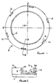
- the body side coupling 8 is integrally molded from a synthetic plastics material, e.g. low density polyethylene material and comprises a thin annular flange 10, a chute 12 upstanding from the flange 10 and surrounding an inlet or stoma aperture 14, and six equispaced projections 16 upstanding from the outer periphery of the flange.
- the inner surface 18 of the chute 12 is cylindrical but the outer surface comprises a chamfered portion 20 and a tapered portion 22 which converges towards the flange.
- the tapered portion 22 is herein referred to as a first seal means and assists in maintaining a seal, as to be described below.
- Each of the locking projections 16 is generally arcuate as seen in plan and comprises an enlarged head portion 24 connected to the surface of the flange by a tapered V-portion 26.
- the radially outer surface of each V-portion 26 includes a detent pip 28 for engaging an associated recess in a locking ring 30 of a bag side coupling as will be described below.
- the lower surface of the flange 10 includes a suitable medical grade adhesive layer 11 which causes the body side coupling to adhere to the body of the user.
- a suitable material is that known as "STOMAHESIVE” (Registered Trade Mark) which comprises a sheet of plastic adhesive material comprising a blend of a water soluble or a water swellable hydrocolloid and a water insoluble viscous elastic binder. Further details are disclosed in U.K. Patent No. 1,088,992.
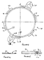
- the bag side coupling includes two separately formed parts: a locking ring 30 ( Figures 3 to 5) and a seal ring 44 ( Figures 6 and 7). Together the seal ring 44 and locking ring 30 are also herein referred to as a bag side support means.
- the locking ring 30 is formed of a synthetic plastics material, e.g. an engineering plastics material and comprises a ring portion 32, a pair of diametrically opposed lugs 34, and six equispaced locking spurs 36 extending from the outer periphery of the locking ring.
- the lugs may be gripped to rotate the ring 30 when locking and unlocking the coupling. They serve, if required, to attach the coupling to a belt.
- the inner surface of the locking ring 30 is stepped at 39 to accommodate the seal ring so that their lower surfaces 41a and 41b are flush (see Figure 8).
- the locking spurs 36 are generally arcuate and each locking spur includes a base portion 37 connected to the ring portion 32 and an elongated portion 39 extending generally circumferentially and spaced apart from the ring portion 32.
- each spur 36 The walls 43 of the slot 38 diverge upwardly (as seen in Figure 5) to be complimentarily shaped to the V-portion 26 of the locking projections 16.
- the spur In the end region 40 of each spur 36, the spur diminishes in axial thickness towards the free end. This tapered lead-in assists engagement of the projections 16 and the slots 38 during the coupling operation.
- the radially inner surface of each end region also includes a recess 42 for receiving the pip 28 of the associated projection 16 to provide a detent action.
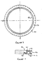
- the seal ring 44 is formed of a synthetic plastics material, e.g. EVA material and includes an outer main body portion 45 having a recess 46 (FIG. 7) extending around the outer circumference for receiving a radially inner portion 47 of the locking ring 30 (see Figure 8).
- the ring 44 also has, optionally, an annular recess 48.
- a flexible and deflectible annular seal lip 50 projects inwardly from the inner periphery of the main body portion 45.
- the wall 53 surrounding the stomal orifice of the ostomy bag is attached to a radially extending surface 52 of the main body portion of the seal ring 44 by suitable means, e.g. welding or adhesive.
- the seal lip 50 is an example of a seal means herein referred to as a second seal means.
- the body side coupling 8 is formed and a layer 11 of adhesive applied to the lower side of the flange 10.
- the locking ring 30 and the seal ring 44 are separately formed and the ostomy bag is secured to the seal ring 44.
- the wearer attaches the body side coupling 8 to his/her peristomal area and then attaches the bag side coupling by maneuvering the bag side coupling relative to the body side coupling so that the projections 16 and the spurs 36 are out of registration.
- the bag side coupling is then pushed in an axial direction towards the other couplings so that the seal lip 50 deforms to ride over the chamfered out surface 20 of the chute 12 to engage the tapered portion 22.
- the flush lower surfaces 41a and 41b of the locking ring 30 and the seal ring 44 respectively, engage or are spaced closely from the upper surface of the flange 10.
- the interaction of the seal lip 50 and the tapered portion 22 provides a generally axial bias force tending to urge the locking ring 30 and the seal ring 44 against the flange 10 and the portions 24.
- locking is achieved by rotating the locking ring so that the elongated portions 39 of the spurs 36 hook under and guide the locking projections 16 into the slots 38, until the pips 28 on the projections locate in the recesses 42 on the spurs.
- the locking ring and the seal ring and the attached bag may rotate as one unit relative to the body side coupling, or the seal ring and the attached bag may be kept stationary while the locking ring is rotated relative to the body side coupling 10 to engage the spurs 36 on the locking ring with the projections 16 on the body side coupling.
- Initial engagement of the spurs with the projections is assisted by the tapered lead-in on the portions 39.
- the coupling is relatively thin when assembled and the locking ring and projections do not add to the overall thickness of the coupling which, in the illustrated example, is dictated by the length of the chute 12 alone.
Landscapes
- Health & Medical Sciences (AREA)
- Epidemiology (AREA)
- Nursing (AREA)
- Orthopedic Medicine & Surgery (AREA)
- Engineering & Computer Science (AREA)
- Biomedical Technology (AREA)
- Heart & Thoracic Surgery (AREA)
- Vascular Medicine (AREA)
- Life Sciences & Earth Sciences (AREA)
- Animal Behavior & Ethology (AREA)
- General Health & Medical Sciences (AREA)
- Public Health (AREA)
- Veterinary Medicine (AREA)
- Orthopedics, Nursing, And Contraception (AREA)
- Telephone Function (AREA)
- Iron Core Of Rotating Electric Machines (AREA)
- Die Bonding (AREA)
Claims (15)
- Ostomiebeutelkupplung mit einem körperseitigen Kupplungselement (8), das eine erste Dichtungseinrichtung (22), die eine Einlaß- oder Stomaöffnung (14) umgibt, und eine körperseitige, die erste Dichtungseinrichtung (22) tragende Halterung (10) aufweist, und einem beutelseitigen Kupplungselement, das eine zweite, mit der ersten Dichtungseinrichtung (22) zusammenwirkende Dichtungseinrichtung (50) und eine der zweiten Dichtungseinrichtung (50) zugeordnete beutelseitige Halterung (30, 44) aufweist, wobei entweder die körperseitige oder die beutelseitige Halterung an mehreren, in Abständen um die Halterung verteilten Stellen Wände aufweist, die jeweils im allgemeinen peripher angeordnete Schlitze (38) bilden, und die jeweils andere Halterung mehrere beabstandete Vorsprünge (16) aufweist, die lösbar in die Schlitze eingreifen sollen, und wobei die Schlitze zum Teil durch entsprechende, peripher verlaufende Sporne (36) abgegrenzt werden, so daß beim Eingriff der ersten mit der zweiten Dichtungseinrichtung (22, 50) und anschließender Drehung der Halterungen gegeneinander in geeigneter Richtung die Vorsprünge (16) in den entsprechenden Schlitzen aufgenommen und dadurch die Kupplung gegen eine Trennbewegung lösbar verriegelt wird.
- Ostomiebeutelkupplung nach Anspruch 1, wobei die Wände jedes der Schlitze (38) an der einen Halterung zu einem Flanschabschnitt (10) der anderen Halterung hin konvergiert und der entsprechende Vorsprung (16) im allgemeinen komplementär geformt ist.
- Ostomiebeutelkupplung nach Anspruch 1 oder 2, wobei die körperseitige Halterung die mehreren beabstandeten Vorsprünge aufweist und in einem Stück mit der zugehörigen Dichtungseinrichtung ausgebildet ist.
- Ostomiebeutelkupplung nach Anspruch 1, 2 oder 3, wobei die beutelseitige Halterung einen Verriegelungsring (30) aufweist und die zugehörige Dichtungseinrichtung (44) getrennt ausgebildet ist, und wobei die einzelnen Sporne (36), die vom Verriegelungsring (30) im allgemeinen in peripherer Richtung ausgehen, in einem gewissen Abstand von der äußeren Umfangsfläche des Verriegelungsrings (30) angeordnet sind.
- Ostomiebeutelkupplung nach Anspruch 4, wobei die freien Enden der Sporne (36) spitz zulaufen, um den Eingriff der Vorsprünge (16) in die entsprechenden Schlitze (38) zu erleichtern.
- Ostomiebeutelkupplung nach Anspruch 4 oder 5, wobei die Dichtungseinrichtung (44) aus Ethylen-Vinylazetat-Kopolymerisat (EVA) geformt ist.
- Ostomiebeutelkupplung nach Anspruch 4 oder 5, wobei der Verriegelungsring (30) aus einem technischem Kunststoff geformt ist.
- Ostomiebeutelkupplung nach irgendeinem der vorstehenden Ansprüche, wobei mindestens einer der Schlitze und einer der Vorsprünge komplementäre Verriegelungseinrichtungen (28, 42) aufweisen.
- Ostomiebeutelkupplung nach irgendeinem der vorstehenden Ansprüche, wobei eine der Dichtungseinrichtungen eine nach innen gerichtete, elastisch verformbare Lippe (50) und die andere Dichtungseinrichtung eine Rinne (12) von im allgemeinen hohlzylindrischer Form mit einer äußeren Umfangsfläche (22) für den Dichtungskontakt mit der nach innen gerichteten Lippe (50) aufweist.
- Ostomiebeutelkupplung nach Anspruch 9, wobei die äußere Umfangsfläche der Rinne eine abgefaste Fläche (20) aufweist.
- Ostomiebeutelkupplung nach Anspruch 4, wobei der Verriegelungsring (30) und die dazugehörige Dichtungseinrichtung (44) gegeneinander drehbar sind.
- Ostomiebeutelkupplung nach Anspruch 4 oder irgendeinem davon abhängigen Anspruch, wobei die beutelseitige Halterung (44) an dem Ostomiebeutel um dessen Einlaßöffnung (14) herum befestigt ist.
- Ostomiebeutelkupplung nach irgendeinem der vorstehenden Ansprüche, wobei die körperseitige und die beutelseitige Halterung in Kontakt miteinander oder in geringem Abstand voneinander angeordnet sind, wenn das körperseitige Kupplungselement an das beutelseitige Kupplungselement angekuppelt ist.
- Ostomiebeutelkupplung nach irgendeinem der vorstehenden Ansprüche, wobei die körperseitigen Vorsprünge (16) von der Rinne (12) beabstandet sind und das beutelseitige Kupplungselement zwischen der äußeren Umfangsfläche (22) der Rinne (12) und einer Innenfläche der Vorsprünge (16) angeordnet ist, mit der Ausnahme, daß die Schlitze (38) mit den Vorsprüngen (16) sowohl an der Außen- als auch an der Innenfläche der Vorsprünge in Eingriff kommen, wenn das beutelseitige Kupplungselement und das körperseitige Kupplungselement miteinander verriegelt werden.
- Ostomiebeutelkupplung nach Anspruch 14, wobei die Wände jedes der Schlitze (38) zu einem Flanschabschnitt (10) des körperseitigen Kupplungselements hin konvergieren und die Innen- und Außenflächen des zugehörigen Vorsprungs (16) komplementär zu den Wänden der Schlitze (38) geformt sind.
Priority Applications (1)
| Application Number | Priority Date | Filing Date | Title |
|---|---|---|---|
| AT89305539T ATE84959T1 (de) | 1988-06-13 | 1989-06-01 | Kupplung fuer ostomiebeutel. |
Applications Claiming Priority (4)
| Application Number | Priority Date | Filing Date | Title |
|---|---|---|---|
| GB888813967A GB8813967D0 (en) | 1988-06-13 | 1988-06-13 | Ostomy bag coupling |
| GB8817995A GB2219507B (en) | 1988-06-13 | 1988-07-28 | An ostomy bag coupling |
| GB8813967 | 1988-07-28 | ||
| GB8817995 | 1988-07-28 |
Publications (2)
| Publication Number | Publication Date |
|---|---|
| EP0347068A1 EP0347068A1 (de) | 1989-12-20 |
| EP0347068B1 true EP0347068B1 (de) | 1993-01-27 |
Family
ID=26294010
Family Applications (1)
| Application Number | Title | Priority Date | Filing Date |
|---|---|---|---|
| EP89305539A Expired - Lifetime EP0347068B1 (de) | 1988-06-13 | 1989-06-01 | Kupplung für Ostomiebeutel |
Country Status (11)
| Country | Link |
|---|---|
| US (1) | US5178615A (de) |
| EP (1) | EP0347068B1 (de) |
| JP (1) | JP2873018B2 (de) |
| AU (1) | AU615072B2 (de) |
| CA (1) | CA1329530C (de) |
| DE (1) | DE68904602T2 (de) |
| DK (1) | DK174383B1 (de) |
| ES (1) | ES2037424T3 (de) |
| IE (1) | IE63736B1 (de) |
| NO (1) | NO172374C (de) |
| NZ (1) | NZ229330A (de) |
Families Citing this family (9)
| Publication number | Priority date | Publication date | Assignee | Title |
|---|---|---|---|---|
| CA2028618C (en) * | 1989-11-17 | 2001-12-11 | Peter Leslie Steer | Ostomy coupling |
| FR2785526B1 (fr) * | 1998-11-06 | 2001-03-30 | Plasto Sa | Dispositif de securite pour colostomie |
| DE10000369A1 (de) * | 2000-01-07 | 2001-07-12 | Bosch Gmbh Robert | Steckverbindungsvorrichtung |
| EP1959881B1 (de) * | 2005-11-24 | 2012-02-29 | Coloplast A/S | Kupplung für Ostomie |
| US8657799B2 (en) * | 2011-11-07 | 2014-02-25 | Georgann M. Carrubba | Ostomy appliance and method |
| RU2692954C2 (ru) * | 2013-08-30 | 2019-06-28 | Брюс ГОЛДСМИТ | Системы и комплекты для приспособлений для ухода за стомой |
| US9757270B2 (en) | 2015-02-09 | 2017-09-12 | Tencar Inc. | Ostomy appliance |
| DK178391B1 (da) * | 2015-03-18 | 2016-10-17 | Multi-Lock Aps | Stomianordning |
| CN116648213A (zh) * | 2020-12-31 | 2023-08-25 | 康沃特克科技公司 | 用于造口术器具的联接系统 |
Family Cites Families (24)
| Publication number | Priority date | Publication date | Assignee | Title |
|---|---|---|---|---|
| GB1021145A (en) * | 1963-03-18 | 1966-03-02 | John Leslie Russell | Colostomy, ileostomy and ureterostomy appliance |
| GB1099455A (en) * | 1963-10-31 | 1968-01-17 | Joseph Benjamin Leigh | Improvements relating to colostomy appliances |
| US3736934A (en) * | 1971-09-21 | 1973-06-05 | A Hennessy | Surgical drainage appliance |
| GB1579875A (en) * | 1977-03-30 | 1980-11-26 | Kingsdown Medical Consultants | Coupling for an ostomy bag |
| NZ186585A (en) * | 1977-03-30 | 1981-03-16 | Kingsdown Medical Consultants | Coupling for joining pad or dressing to an ostomy bag |
| BE853876A (fr) * | 1977-04-22 | 1977-08-16 | Maricot Jose | Ensemble demontable pour colostomie, et articles colles et soudes pour cet usage |
| GB1568860A (en) * | 1978-03-21 | 1980-06-04 | Kingsdown Medical Consultants | Coupling for an ostomy bag |
| US4586927A (en) * | 1981-08-17 | 1986-05-06 | E. R. Squibb & Sons, Inc. | Irrigation sleeve and attachment therefor |
| GB2121902B (en) * | 1982-03-11 | 1985-07-31 | Craig Med Prod Ltd | A coupling for an ostomy bag |
| GB2142399A (en) * | 1983-07-01 | 1985-01-16 | Craig Med Prod Ltd | Coupling for an ostomy bag |
| GB2179556B (en) * | 1983-11-01 | 1987-09-23 | Craig Med Prod Ltd | Ostomy appliance |
| GB8403237D0 (en) * | 1984-02-07 | 1984-03-14 | Edwards J V | Ostomy appliance |
| DE3417183A1 (de) * | 1984-05-09 | 1985-11-14 | Gerald Dr. 8000 München Hauer | Anus-praeter-versorgungssystem |
| GB2163350B (en) * | 1984-08-20 | 1988-01-20 | Craig Med Prod Ltd | Ostomy appliance coupling elements |
| GB2177924A (en) * | 1985-07-16 | 1987-02-04 | Craig Med Prod Ltd | Side coupling element for ostomy appliances |
| GB2183481B (en) * | 1985-12-10 | 1989-10-11 | Craig Med Prod Ltd | Ostomy appliance |
| AU601194B2 (en) * | 1986-07-31 | 1990-09-06 | E.R. Squibb & Sons, Inc. | Ostomy coupling |
| GB8618692D0 (en) * | 1986-07-31 | 1986-09-10 | Craig Med Prod Ltd | Ostomy coupling |
| GB8618693D0 (en) * | 1986-07-31 | 1986-09-10 | Craig Med Prod Ltd | Ostomy coupling |
| GB8629424D0 (en) * | 1986-12-09 | 1987-01-21 | Craig Med Prod Ltd | Ostomy bag coupling |
| GB2201345B (en) * | 1987-01-27 | 1990-09-26 | Craig Med Prod Ltd | Coupling for ostomy and like bags |
| GB2201346B (en) * | 1987-02-05 | 1989-04-26 | Craig Med Prod Ltd | Ostomy coupling |
| US4820285A (en) * | 1987-09-16 | 1989-04-11 | E.R. Squibb & Sons, Inc. | Bayonet coupling for ostomy device |
| GB2227667B (en) * | 1989-02-03 | 1992-07-29 | Squibb & Sons Inc | Ostomy coupling |
-
1989
- 1989-05-29 NZ NZ229330A patent/NZ229330A/en unknown
- 1989-06-01 EP EP89305539A patent/EP0347068B1/de not_active Expired - Lifetime
- 1989-06-01 DE DE8989305539T patent/DE68904602T2/de not_active Expired - Lifetime
- 1989-06-01 AU AU35921/89A patent/AU615072B2/en not_active Ceased
- 1989-06-01 ES ES198989305539T patent/ES2037424T3/es not_active Expired - Lifetime
- 1989-06-12 NO NO892398A patent/NO172374C/no not_active IP Right Cessation
- 1989-06-12 IE IE187889A patent/IE63736B1/en unknown
- 1989-06-12 DK DK198902860A patent/DK174383B1/da not_active IP Right Cessation
- 1989-06-13 JP JP1152041A patent/JP2873018B2/ja not_active Expired - Fee Related
- 1989-06-13 CA CA000602659A patent/CA1329530C/en not_active Expired - Fee Related
- 1989-06-13 US US07/365,410 patent/US5178615A/en not_active Expired - Lifetime
Also Published As
| Publication number | Publication date |
|---|---|
| NO172374B (no) | 1993-04-05 |
| CA1329530C (en) | 1994-05-17 |
| DK286089D0 (da) | 1989-06-12 |
| IE63736B1 (en) | 1995-06-14 |
| IE891878L (en) | 1990-01-28 |
| NO892398L (no) | 1989-12-14 |
| ES2037424T3 (es) | 1993-06-16 |
| US5178615A (en) | 1993-01-12 |
| DK286089A (da) | 1989-12-14 |
| AU3592189A (en) | 1989-12-14 |
| DE68904602D1 (de) | 1993-03-11 |
| JPH0231753A (ja) | 1990-02-01 |
| NO892398D0 (no) | 1989-06-12 |
| NO172374C (no) | 1993-07-14 |
| EP0347068A1 (de) | 1989-12-20 |
| AU615072B2 (en) | 1991-09-19 |
| DE68904602T2 (de) | 1993-05-19 |
| DK174383B1 (da) | 2003-01-20 |
| NZ229330A (en) | 1992-07-28 |
| JP2873018B2 (ja) | 1999-03-24 |
Similar Documents
| Publication | Publication Date | Title |
|---|---|---|
| EP1407731B1 (de) | Ostomiekupplung | |
| EP1223022B1 (de) | Verfahren zum Formen von Kunststoffgegenständen und so hergestellte Gegenstände | |
| EP0373782B1 (de) | Ostomiekupplung | |
| CA2186656C (en) | An ostomy coupling | |
| US4929245A (en) | Safety device for ostomy bag coupling system | |
| JP2930642B2 (ja) | 人工肛門用カップリング | |
| GB2344998A (en) | Ostomy coupling | |
| EP0347068B1 (de) | Kupplung für Ostomiebeutel | |
| US5139492A (en) | Two-piece ostomy appliance with sliding transverse interlock | |
| EP0737458A2 (de) | Kupplung | |
| JPH0626554B2 (ja) | 人工肛門用具 | |
| AU745167B2 (en) | Coupling for ostomy appliance, and ostomy appliance comprising such a coupling | |
| JP2777182B2 (ja) | 人工肛門用カップリング | |
| GB2219507A (en) | An ostomy bag coupling | |
| EP0680736B1 (de) | Ostomiekupplung | |
| EP0650709B1 (de) | Ostomiekupplung | |
| AU684121B2 (en) | Ostomy coupling | |
| GB2316317A (en) | 3-part ostomy coupling with a flexible locking ring | |
| MXPA00000121A (en) | Ostomy coupling |
Legal Events
| Date | Code | Title | Description |
|---|---|---|---|
| PUAI | Public reference made under article 153(3) epc to a published international application that has entered the european phase |
Free format text: ORIGINAL CODE: 0009012 |
|
| AK | Designated contracting states |
Kind code of ref document: A1 Designated state(s): AT BE CH DE ES FR GB GR IT LI LU NL SE |
|
| 17P | Request for examination filed |
Effective date: 19900530 |
|
| 17Q | First examination report despatched |
Effective date: 19910708 |
|
| GRAA | (expected) grant |
Free format text: ORIGINAL CODE: 0009210 |
|
| AK | Designated contracting states |
Kind code of ref document: B1 Designated state(s): AT BE CH DE ES FR GR IT LI LU NL SE |
|
| REF | Corresponds to: |
Ref document number: 84959 Country of ref document: AT Date of ref document: 19930215 Kind code of ref document: T |
|
| ET | Fr: translation filed | ||
| REF | Corresponds to: |
Ref document number: 68904602 Country of ref document: DE Date of ref document: 19930311 |
|
| ITF | It: translation for a ep patent filed | ||
| REG | Reference to a national code |
Ref country code: ES Ref legal event code: FG2A Ref document number: 2037424 Country of ref document: ES Kind code of ref document: T3 |
|
| REG | Reference to a national code |
Ref country code: GR Ref legal event code: FG4A Free format text: 3007615 |
|
| PLBE | No opposition filed within time limit |
Free format text: ORIGINAL CODE: 0009261 |
|
| STAA | Information on the status of an ep patent application or granted ep patent |
Free format text: STATUS: NO OPPOSITION FILED WITHIN TIME LIMIT |
|
| 26N | No opposition filed | ||
| EPTA | Lu: last paid annual fee | ||
| EAL | Se: european patent in force in sweden |
Ref document number: 89305539.2 |
|
| PGFP | Annual fee paid to national office [announced via postgrant information from national office to epo] |
Ref country code: LU Payment date: 20000609 Year of fee payment: 12 |
|
| PGFP | Annual fee paid to national office [announced via postgrant information from national office to epo] |
Ref country code: AT Payment date: 20000613 Year of fee payment: 12 Ref country code: CH Payment date: 20000613 Year of fee payment: 12 |
|
| PGFP | Annual fee paid to national office [announced via postgrant information from national office to epo] |
Ref country code: GR Payment date: 20000630 Year of fee payment: 12 |
|
| PGFP | Annual fee paid to national office [announced via postgrant information from national office to epo] |
Ref country code: BE Payment date: 20000814 Year of fee payment: 12 |
|
| PG25 | Lapsed in a contracting state [announced via postgrant information from national office to epo] |
Ref country code: LU Free format text: LAPSE BECAUSE OF NON-PAYMENT OF DUE FEES Effective date: 20010601 Ref country code: AT Free format text: LAPSE BECAUSE OF NON-PAYMENT OF DUE FEES Effective date: 20010601 |
|
| PG25 | Lapsed in a contracting state [announced via postgrant information from national office to epo] |
Ref country code: LI Free format text: LAPSE BECAUSE OF NON-PAYMENT OF DUE FEES Effective date: 20010630 Ref country code: CH Free format text: LAPSE BECAUSE OF NON-PAYMENT OF DUE FEES Effective date: 20010630 Ref country code: BE Free format text: LAPSE BECAUSE OF NON-PAYMENT OF DUE FEES Effective date: 20010630 Ref country code: GR Free format text: LAPSE BECAUSE OF NON-PAYMENT OF DUE FEES Effective date: 20010630 |
|
| BERE | Be: lapsed |
Owner name: E.R. SQUIBB & SONS INC. Effective date: 20010630 |
|
| REG | Reference to a national code |
Ref country code: CH Ref legal event code: PL |
|
| PGFP | Annual fee paid to national office [announced via postgrant information from national office to epo] |
Ref country code: NL Payment date: 20070523 Year of fee payment: 19 |
|
| PGFP | Annual fee paid to national office [announced via postgrant information from national office to epo] |
Ref country code: SE Payment date: 20070607 Year of fee payment: 19 |
|
| PGFP | Annual fee paid to national office [announced via postgrant information from national office to epo] |
Ref country code: ES Payment date: 20070717 Year of fee payment: 19 |
|
| PGFP | Annual fee paid to national office [announced via postgrant information from national office to epo] |
Ref country code: IT Payment date: 20070626 Year of fee payment: 19 |
|
| PGFP | Annual fee paid to national office [announced via postgrant information from national office to epo] |
Ref country code: DE Payment date: 20080605 Year of fee payment: 20 |
|
| PGFP | Annual fee paid to national office [announced via postgrant information from national office to epo] |
Ref country code: FR Payment date: 20080617 Year of fee payment: 20 |
|
| EUG | Se: european patent has lapsed | ||
| NLV4 | Nl: lapsed or anulled due to non-payment of the annual fee |
Effective date: 20090101 |
|
| PG25 | Lapsed in a contracting state [announced via postgrant information from national office to epo] |
Ref country code: NL Free format text: LAPSE BECAUSE OF NON-PAYMENT OF DUE FEES Effective date: 20090101 |
|
| REG | Reference to a national code |
Ref country code: ES Ref legal event code: FD2A Effective date: 20080602 |
|
| PG25 | Lapsed in a contracting state [announced via postgrant information from national office to epo] |
Ref country code: IT Free format text: LAPSE BECAUSE OF NON-PAYMENT OF DUE FEES Effective date: 20080601 |
|
| PG25 | Lapsed in a contracting state [announced via postgrant information from national office to epo] |
Ref country code: ES Free format text: LAPSE BECAUSE OF NON-PAYMENT OF DUE FEES Effective date: 20080602 |
|
| PG25 | Lapsed in a contracting state [announced via postgrant information from national office to epo] |
Ref country code: SE Free format text: LAPSE BECAUSE OF NON-PAYMENT OF DUE FEES Effective date: 20080602 |