EP0346952A2 - Gerät zum Melken von Tieren, wie zum Beispiel Kühen - Google Patents
Gerät zum Melken von Tieren, wie zum Beispiel Kühen Download PDFInfo
- Publication number
- EP0346952A2 EP0346952A2 EP89116115A EP89116115A EP0346952A2 EP 0346952 A2 EP0346952 A2 EP 0346952A2 EP 89116115 A EP89116115 A EP 89116115A EP 89116115 A EP89116115 A EP 89116115A EP 0346952 A2 EP0346952 A2 EP 0346952A2
- Authority
- EP
- European Patent Office
- Prior art keywords
- milking
- teat cups
- implement
- teat
- envelope
- Prior art date
- Legal status (The legal status is an assumption and is not a legal conclusion. Google has not performed a legal analysis and makes no representation as to the accuracy of the status listed.)
- Pending
Links
- 241001465754 Metazoa Species 0.000 title claims abstract description 24
- 241000283690 Bos taurus Species 0.000 title claims abstract description 16
- 210000002445 nipple Anatomy 0.000 claims abstract description 76
- 210000000481 breast Anatomy 0.000 claims abstract description 24
- 239000008267 milk Substances 0.000 claims description 12
- 210000004080 milk Anatomy 0.000 claims description 12
- 235000013336 milk Nutrition 0.000 claims description 12
- 239000012780 transparent material Substances 0.000 claims description 2
- 239000007788 liquid Substances 0.000 description 7
- 230000010349 pulsation Effects 0.000 description 5
- 238000009434 installation Methods 0.000 description 3
- 238000009877 rendering Methods 0.000 description 3
- 238000011109 contamination Methods 0.000 description 2
- 210000003608 fece Anatomy 0.000 description 2
- 239000010871 livestock manure Substances 0.000 description 2
- 229910000831 Steel Inorganic materials 0.000 description 1
- 230000006978 adaptation Effects 0.000 description 1
- 230000017531 blood circulation Effects 0.000 description 1
- 229940000425 combination drug Drugs 0.000 description 1
- 238000007599 discharging Methods 0.000 description 1
- 238000006073 displacement reaction Methods 0.000 description 1
- 238000001035 drying Methods 0.000 description 1
- 230000000694 effects Effects 0.000 description 1
- 238000000034 method Methods 0.000 description 1
- 239000010959 steel Substances 0.000 description 1
- 230000000638 stimulation Effects 0.000 description 1
- 229920002994 synthetic fiber Polymers 0.000 description 1
- XLYOFNOQVPJJNP-UHFFFAOYSA-N water Substances O XLYOFNOQVPJJNP-UHFFFAOYSA-N 0.000 description 1
Images


Classifications
-
- A—HUMAN NECESSITIES
- A01—AGRICULTURE; FORESTRY; ANIMAL HUSBANDRY; HUNTING; TRAPPING; FISHING
- A01J—MANUFACTURE OF DAIRY PRODUCTS
- A01J5/00—Milking machines or devices
- A01J5/04—Milking machines or devices with pneumatic manipulation of teats
- A01J5/041—Milk claw
-
- A—HUMAN NECESSITIES
- A01—AGRICULTURE; FORESTRY; ANIMAL HUSBANDRY; HUNTING; TRAPPING; FISHING
- A01J—MANUFACTURE OF DAIRY PRODUCTS
- A01J5/00—Milking machines or devices
- A01J5/04—Milking machines or devices with pneumatic manipulation of teats
-
- A—HUMAN NECESSITIES
- A01—AGRICULTURE; FORESTRY; ANIMAL HUSBANDRY; HUNTING; TRAPPING; FISHING
- A01J—MANUFACTURE OF DAIRY PRODUCTS
- A01J5/00—Milking machines or devices
- A01J5/04—Milking machines or devices with pneumatic manipulation of teats
- A01J5/06—Teat-cups with one chamber
-
- A—HUMAN NECESSITIES
- A01—AGRICULTURE; FORESTRY; ANIMAL HUSBANDRY; HUNTING; TRAPPING; FISHING
- A01J—MANUFACTURE OF DAIRY PRODUCTS
- A01J5/00—Milking machines or devices
- A01J5/04—Milking machines or devices with pneumatic manipulation of teats
- A01J5/08—Teat-cups with two chambers
-
- A—HUMAN NECESSITIES
- A01—AGRICULTURE; FORESTRY; ANIMAL HUSBANDRY; HUNTING; TRAPPING; FISHING
- A01J—MANUFACTURE OF DAIRY PRODUCTS
- A01J7/00—Accessories for milking machines or devices
- A01J7/04—Accessories for milking machines or devices for treatment of udders or teats, e.g. for cleaning
-
- A—HUMAN NECESSITIES
- A01—AGRICULTURE; FORESTRY; ANIMAL HUSBANDRY; HUNTING; TRAPPING; FISHING
- A01K—ANIMAL HUSBANDRY; AVICULTURE; APICULTURE; PISCICULTURE; FISHING; REARING OR BREEDING ANIMALS, NOT OTHERWISE PROVIDED FOR; NEW BREEDS OF ANIMALS
- A01K1/00—Housing animals; Equipment therefor
- A01K1/12—Milking stations
Definitions
- the invention relates to a milking implement for animals, such as cows, comprising a milking cluster with teat cups which can be attached to the teats of an animal's udder.
- the invention envisages a milking implement, enabling an efficient manner of milking, the risk of damage to or contamination of parts of the milking machine being minimal and a proper attachment of the relative parts of the milking implement to the udder of the animal being ensured.
- the milking implement according to the invention is characterized in that the milking cluster with the teat cups are encompassed by an envelope that can be placed around the udder of the animal.
- the envelope Preferably, at least part of the envelope is made from transparent material.
- the envelope may comprise a flexible upper rim, which ensures a proper attachment against the udder of the animal.
- the GB patent specification 918,766 describes a milking implement, whereby the separate teat cups are poured into an envelope encompassing the animal's udder. In that milking implement, the movability of the teat cups with respect to each other is seriously limited.
- the Soviet patent specification 667,189 describes a milking implement, whereby the separate teat cups are located in ball joints, fitted in a horizontal bar, which is supported by an envelope encompassing the animal's udder.
- the movability of the teat cups with respect to each other is rather limited; the implement shows a movability around a vertical axis, but not movability in a horizontal plane.
- the envelope can furthermore be attached to the body of the animal by means of a carrying member, said carrying member supporting the teat cups.
- a carrying member supporting the teat cups.
- the teat cups are connected with a central portion supported by the carrying member.
- the teat cups are movable with respect to each other in a horizontal plane.
- the teat cups are thereto attached to said central portion by means of one or more pivots.
- the milk conduits connected to respective teat cups are attached to the carrying member.
- the carrying member comprises one or more straps or strings, which may be provided on various spots across and around the animal.
- the carrying member may be adjustable.
- the animal has a fair degree of room to move, i.e. to walk, stand or lie without the attachment of the milking implement onto the udder of the animal being affected.
- Figure 1 shows a plan view of a parlour which comprises two rows of milking sites 1.
- the milking sites are provided with a feeding gutter 2 at the front and with a conveyor 3 for discharging manure at the back.
- a set of conduits 4 is arranged underneath the above-mentioned milking sites, said conduits being designed in such a way that an attachment to conduits 4 can be brought about in each milking site.
- the conduits 4 comprise one or more liquid and/or air pipes.
- a schematic rendering of a milk tank 5 is given, which also goes for a tank 6 for water, rinsing liquid or cleansing liquid.
- a tank 7 for compressed air is also rendered.
- a pump if at all provided, for bringing about an under-pressure, is not further detailed.
- the installation may further comprise a computer 8 and control means 9 for an automatic control, check and/or protection of the installation.
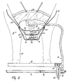
- FIG. 2 shows a cow 10, occupying a milking site.
- Said cow 10 is provided with a milking cluster 11, which may be permanently connected to the udder of the cow.
- the milking cluster 11 comprises an envelope 12, made of a transparent synthetic material and attached to the cow by means of straps 13. Contained within the envelope 12 are the teat cups 14, which will be further explained.
- the floor of the milking parlour consists of a conveyor with mutually coupled, movable elements 15, linked to one another in the shape of an endless conveyor.
- the conveyor is provided with two final guiding members 16, about which the elements 15 can move, and with a support 17 to stay the elements 15, constituting the floor of the milking site 1.
- connection box 18 is provided, through which connection box an under-pressure, cleansing or rinsing liquid and/or preheated air can be supplied and milk, and possibly other liquids, discharged.
- connection box 18 an under-pressure, cleansing or rinsing liquid and/or preheated air can be supplied and milk, and possibly other liquids, discharged.
- the necessary conduits 19 are led from the milking cluster 11 to the connection box 18.
- a grating 20 is rendered, allowing the manure and other defilements, if any, to fall through, then to be transported by discharge means, which are not rendered in Figure 2.
- FIG 3 shows a cross-section of the transparent envelope 12, containing four teat cups 14, of which two are visible.
- the teat cups are provided with a connection, directed forwardly, in view of the necessary conduits.
- the upper rim 22 of the teat cup is adapted to the shape of the udder, so that a proper attachment to the udder can be obtained.
- the upper rim 22 is set in the flexible upper part 23 of the teat cup.
- the straps 13, ensuring the attachment of the milking cluster to the cow carry both the envelope 12 and a central portion 24, to which the teat cups 14 are connected.
- the teat cups are linked with the connection box 18 near the floor of the milking site.
- the floor of the milking site consists of elements 15, mutually connected and guided around the chain wheels 25, as an endless conveyor.
- One or more of the chain wheels 25 may be driven by means which are not further defined, such as an electric motor.
- FIG 4 shows, in a way similar to that of Figure 3, the milking cluster in a lateral view.
- the envelope 12 is provided with a flexible upper rim 26, making it possible to obtain a proper attachment to the udder of the cow.
- a unit 27, attached to one of the straps 13, is rendered.
- Said unit 27 may comprise a pulsator for achieving a varying air pressure.
- the unit 27 may comprise the necessary valves and other means for the performance of the milking cluster.
- a cross-section is given of the elements 15, constituting the floor, said elements consisting of e.g. steel beams with a closed profile and being mutually linked up by means of shackles 28, constituting a chain which engages with the chain wheels 25.
- FIG. 5 shows in more detail a first embodiment of the milking cluster. It comprises a schematic rendering of the udder 30 with the teats 31 of the cow.
- the udder 30 is encompassed by the transparent envelope 12 which is attached to the cow by means of a strap 13. Contained within the envelope 12 is a central portion 24, which is also connected to strap 13 by means of a bolt 32. Attached to the central portion 24 are the four teat cups 14, a cross-section of two such cups being provided in Figure 5.
- the teat cups 14 are provided on the upper side with a flexible top part 23, which may have such a shape that the required attachment to the udder can be obtained.
- the upper part 23 may, because of its flexibility, adapt itself to the shape of the udder, it may be desirable to pre-shape said upper part in such a manner, that a shape is obtained which matches the average size of an udder. In that case the upper part 23 will not have a symmetric shape.
- the teat cups 14, rendered in Figure 5, are relatively short, i.e. they have a comparatively small size in height and, accordingly, the teat 31 will extend to the vicinity of the teat cup's lowermost side.
- the teat holder 33 is provided, said holder being integrally connected with the flexible upper part 23 and encompassing the teat when the latter is present in the teat cup.
- a chamber 34 is provided, in which a varying air pressure can be brought about via a pulsation conduit, so that the chamber 34 is connected with the pulsator which is not rendered in this Figure.
- the pulsation hose 35 debouches into the chamber 34 through an aperture 36.
- sensors 37 which can detect if the teats occupy a correct position in the teat cup.
- the sensors 37 are connected by means of electrical conduits 38 to a control unit which is not shown in Figure 5.
- said electrical conduits are guided through the pulsation hoses 35.
- the milk hoses 39 shown in Figure 5, ensure the discharge of milk and are mounted in a lateral position with regard to the teat cups 14 in such a manner that the total height of the teat cup scarcely exceeds the length of the teat 31.
- a compact teat cup can be obtained, its height being less than twice the diameter.
- an advantage of such a teat cup is that the parts of the milking cluster do not project downwardly farther than necessary, which reduces the risk of the animal kicking the milking cluster down.
- Figure 6 is a schematic bottom view of the milking cluster, shown in Figure 5.
- Figure 6 renders four milk hoses 39 and four pulsation hoses 35, each of which leads to a teat cup 14.
- the teat cups 14 are connected, by means of mutually pivotable arms 40, to the central portion that is attached to the strap 13. Accordingly, the teat cups are allowed to move in respect of one another in a substantially level plane, enabled to do so also because the hoses 35 and 39 are sufficiently flexible for that purpose. Therefore, the milking cluster can adapt itself to the position of the teats, which position may vary according to the state or condition of the udder.
- Figure 7 shows a second embodiment, without pulsa tion hoses being provided.
- the teat holder 33 is provided with sensors 37, which are capable of observing the presence and/or correct position of the teats in the teat cups.
- the chamber 34 around the teat holder is not subjected to a varying air pressure, but may constitute a resilient air cushion, respectively be equipped with a breather opening, so that the atmospheric air pressure is maintained in chamber 34.
- a varying pressure is brought about, e.g. a varying sequence of under-pressure and atmospheric pressure.
- the teat cup 14 is provided with an embossment device 41 which prevents the teat cup from shutting off the locking hole.
- Figure 8 shows a bottom view of the milking cluster according to Figure 7. From said Figure it is clear that the embossment devices 41 at the lowermost sides of the teat cups 14 have a slightly protracted shape. It is preferable that the low and high pressure in the various teat cups should be brought about in such a way, that two teat cups, situated diagonally in respect of one another, are subjected simultaneously to a low, respectively to a high pressure, as indicated by the arrows 44. A certain upward movement of the milking cluster may result from the varied suction, which may have a positive influence on the milking process.
- Figure 9 shows a teat cup which is provided with a teat holder 33 with substantially annular, upwardly directed lamellae 43. These lamellae 43 may lean against the teat and prevent air from being sucked on along the teat in those periods when an under-pressure prevails in the milk hose. Air or liquid is allowed to escape along the teat, however, if a sufficient exceed pressure is brought about in the milk hose, e.g. during cleansing or drying of the teat.
Landscapes
- Life Sciences & Earth Sciences (AREA)
- Environmental Sciences (AREA)
- Animal Husbandry (AREA)
- Zoology (AREA)
- Biodiversity & Conservation Biology (AREA)
- External Artificial Organs (AREA)
- Feeding And Watering For Cattle Raising And Animal Husbandry (AREA)
- Housing For Livestock And Birds (AREA)
Applications Claiming Priority (4)
| Application Number | Priority Date | Filing Date | Title |
|---|---|---|---|
| NL8502083A NL8502083A (nl) | 1985-07-19 | 1985-07-19 | Inrichting voor het melken van dieren, zoals koeien, in een stal. |
| NL8502082A NL8502082A (nl) | 1985-07-19 | 1985-07-19 | Melkmachine voorzien van een of meer melkbekers en melkstal. |
| NL8502082 | 1985-07-19 | ||
| NL8502083 | 1985-07-19 |
Related Parent Applications (2)
| Application Number | Title | Priority Date | Filing Date |
|---|---|---|---|
| EP86201254.9 Division | 1986-07-17 | ||
| EP19860201254 Division EP0209205B2 (de) | 1985-07-19 | 1986-07-17 | Gerät zum Melken von Tieren, wie zum Beispiel Kühen in einem Stall |
Publications (2)
| Publication Number | Publication Date |
|---|---|
| EP0346952A2 true EP0346952A2 (de) | 1989-12-20 |
| EP0346952A3 EP0346952A3 (de) | 1990-02-14 |
Family
ID=26646057
Family Applications (4)
| Application Number | Title | Priority Date | Filing Date |
|---|---|---|---|
| EP19890116116 Expired EP0347955B1 (de) | 1985-07-19 | 1986-07-17 | Gerät zum Melken von Tieren, zum Beispiel von Kühen |
| EP19860201254 Expired - Lifetime EP0209205B2 (de) | 1985-07-19 | 1986-07-17 | Gerät zum Melken von Tieren, wie zum Beispiel Kühen in einem Stall |
| EP89116115A Pending EP0346952A3 (de) | 1985-07-19 | 1986-07-17 | Gerät zum Melken von Tieren, wie zum Beispiel Kühen |
| EP19890116114 Expired EP0347954B1 (de) | 1985-07-19 | 1986-07-17 | Gerät zum Melken von Tieren, wie zum Beispiel Kühen |
Family Applications Before (2)
| Application Number | Title | Priority Date | Filing Date |
|---|---|---|---|
| EP19890116116 Expired EP0347955B1 (de) | 1985-07-19 | 1986-07-17 | Gerät zum Melken von Tieren, zum Beispiel von Kühen |
| EP19860201254 Expired - Lifetime EP0209205B2 (de) | 1985-07-19 | 1986-07-17 | Gerät zum Melken von Tieren, wie zum Beispiel Kühen in einem Stall |
Family Applications After (1)
| Application Number | Title | Priority Date | Filing Date |
|---|---|---|---|
| EP19890116114 Expired EP0347954B1 (de) | 1985-07-19 | 1986-07-17 | Gerät zum Melken von Tieren, wie zum Beispiel Kühen |
Country Status (2)
| Country | Link |
|---|---|
| EP (4) | EP0347955B1 (de) |
| DE (3) | DE3686724T2 (de) |
Families Citing this family (6)
| Publication number | Priority date | Publication date | Assignee | Title |
|---|---|---|---|---|
| NL9200051A (nl) * | 1992-01-13 | 1993-08-02 | Prolion Bv | Automatische melkinrichting. |
| US5586518A (en) * | 1995-03-27 | 1996-12-24 | Dec International, Inc. | Milking cluster air fork |
| SE9602877D0 (sv) * | 1996-07-26 | 1996-07-26 | Tetra Laval Holdings & Finance | An apparatus for housing an animal to be subjected to an animalrelated action |
| SE9602878D0 (sv) * | 1996-07-26 | 1996-07-26 | Tetra Laval Holdings & Finance | A stall for housing an animal to be subjected to an animal-related action |
| NL1007224C2 (nl) * | 1997-10-08 | 1999-04-09 | Maasland Nv | Tepelvoering die kan worden toegepast in een melkbeker voor het melken van dieren. |
| GB2641714A (en) * | 2024-05-27 | 2025-12-17 | Trakia Univ | Veterinary medical device |
Citations (3)
| Publication number | Priority date | Publication date | Assignee | Title |
|---|---|---|---|---|
| GB918766A (en) | 1959-02-03 | 1963-02-20 | Edward David Dyke | Milking equipment |
| SU667189A1 (ru) | 1977-12-14 | 1979-06-15 | Fomin Leonid U | Устройство дл надевани доильных стаканов на соски вымени |
| SU667198A1 (ru) | 1975-03-14 | 1979-06-15 | Московский Ордена Трудового Красного Знамени Инженерно-Физический Институт | Электростимул тор |
Family Cites Families (10)
| Publication number | Priority date | Publication date | Assignee | Title |
|---|---|---|---|---|
| DD82592A (de) * | ||||
| GB496767A (en) * | 1936-08-26 | 1938-12-06 | Berndt Victor Orre | Improved teat element for milking machines |
| US3176654A (en) * | 1962-02-21 | 1965-04-06 | Us Industries Inc | Milking device |
| US4010714A (en) * | 1974-03-08 | 1977-03-08 | Director, National Institute Of Animal Industry | System for managing milking-cows in stanchion stool |
| DE2622794A1 (de) * | 1976-05-21 | 1977-12-08 | Alfa Laval Agrar Gmbh | Verfahren und vorrichtung zur automatisierten anwendung von sanitisern an strichen und melkzeug |
| DE2812027A1 (de) * | 1978-03-18 | 1979-09-20 | Georg Weiss | Gummipressluftmelkerkombination |
| SE8201338L (sv) * | 1982-03-04 | 1983-09-05 | Alfa Laval Ab | Spenkopp for mjolkningsmaskin |
| SE430559B (sv) * | 1982-04-08 | 1983-11-28 | Alfa Laval Ab | Sett att mjolka och anordning herfor |
| NL8304498A (nl) * | 1983-12-30 | 1985-07-16 | Ir Roelof Geert Middel En Rink | Inrichting voor het melken van vee en werkwijze voor het bedrijven van een dergelijke inrichting. |
| JPH09138077A (ja) * | 1995-11-10 | 1997-05-27 | Tokai Konetsu Kogyo Co Ltd | マイクロ波加熱装置 |
-
1986
- 1986-07-17 EP EP19890116116 patent/EP0347955B1/de not_active Expired
- 1986-07-17 DE DE19863686724 patent/DE3686724T2/de not_active Expired - Fee Related
- 1986-07-17 DE DE8686201254T patent/DE3679245D1/de not_active Expired - Fee Related
- 1986-07-17 EP EP19860201254 patent/EP0209205B2/de not_active Expired - Lifetime
- 1986-07-17 EP EP89116115A patent/EP0346952A3/de active Pending
- 1986-07-17 DE DE19863686726 patent/DE3686726T2/de not_active Expired - Fee Related
- 1986-07-17 EP EP19890116114 patent/EP0347954B1/de not_active Expired
Patent Citations (3)
| Publication number | Priority date | Publication date | Assignee | Title |
|---|---|---|---|---|
| GB918766A (en) | 1959-02-03 | 1963-02-20 | Edward David Dyke | Milking equipment |
| SU667198A1 (ru) | 1975-03-14 | 1979-06-15 | Московский Ордена Трудового Красного Знамени Инженерно-Физический Институт | Электростимул тор |
| SU667189A1 (ru) | 1977-12-14 | 1979-06-15 | Fomin Leonid U | Устройство дл надевани доильных стаканов на соски вымени |
Also Published As
| Publication number | Publication date |
|---|---|
| DE3686726D1 (de) | 1992-10-15 |
| EP0347955A3 (en) | 1990-02-28 |
| EP0347955A2 (de) | 1989-12-27 |
| EP0209205B2 (de) | 1997-06-18 |
| EP0209205B1 (de) | 1991-05-15 |
| EP0346952A3 (de) | 1990-02-14 |
| DE3686724D1 (de) | 1992-10-15 |
| DE3686724T2 (de) | 1993-04-08 |
| EP0347954A2 (de) | 1989-12-27 |
| EP0347954B1 (de) | 1992-09-09 |
| DE3686726T2 (de) | 1993-04-08 |
| DE3679245D1 (de) | 1991-06-20 |
| EP0347954A3 (en) | 1990-01-31 |
| EP0347955B1 (de) | 1992-09-09 |
| EP0209205A1 (de) | 1987-01-21 |
Similar Documents
| Publication | Publication Date | Title |
|---|---|---|
| EP0555895B1 (de) | Vorrichtung zum Melken von Tieren | |
| EP1754411A3 (de) | Verfahren zum automatischen Melken von Tieren und Vorrichtung zu dessen Anwendung | |
| US3999516A (en) | Milker with resilient pulsator manifold mounting | |
| EP0634097A1 (de) | Gerät zum automatischen Melken von Tieren | |
| EP1138193B1 (de) | Vorrichtung zum Melken von Tieren | |
| JP2001500747A (ja) | 動物の自動搾乳装置を含む構造 | |
| US3726252A (en) | Automatic milker | |
| EP0346952A2 (de) | Gerät zum Melken von Tieren, wie zum Beispiel Kühen | |
| US6142098A (en) | Teat cup and a milking robot comprising same | |
| IL132295A0 (en) | A method of automatically milking animals and a fully automatic milking machine provided with a milking robot | |
| EP0693871B2 (de) | Gerät zum automatischen melken von tieren | |
| US6532893B1 (en) | Device arranged to carry a set of teatcups | |
| EP0209206B1 (de) | Vorrichtung zum Melken | |
| NO792712L (no) | Anordning for melkerom. | |
| RU2226822C2 (ru) | Передвижной доильный агрегат | |
| US20060219180A1 (en) | Set of teatcups, and a milking member | |
| US3818866A (en) | Milker | |
| EP1214877B1 (de) | Verfahren zum Melken von Tieren | |
| US20060254524A1 (en) | Milking claw | |
| US5855183A (en) | Teat cup assembly | |
| NL8502082A (nl) | Melkmachine voorzien van een of meer melkbekers en melkstal. | |
| RU2150191C1 (ru) | Доильный аппарат для высокопродуктивных коров | |
| EP0069560A1 (de) | Melkeinrichtung | |
| NZ794563B2 (en) | Means for milking animals | |
| NZ794563A (en) | Means for milking animals |
Legal Events
| Date | Code | Title | Description |
|---|---|---|---|
| PUAI | Public reference made under article 153(3) epc to a published international application that has entered the european phase |
Free format text: ORIGINAL CODE: 0009012 |
|
| AC | Divisional application: reference to earlier application |
Ref document number: 209205 Country of ref document: EP |
|
| AK | Designated contracting states |
Kind code of ref document: A2 Designated state(s): DE FR GB NL SE |
|
| PUAL | Search report despatched |
Free format text: ORIGINAL CODE: 0009013 |
|
| AK | Designated contracting states |
Kind code of ref document: A3 Designated state(s): DE FR GB NL SE |
|
| 17P | Request for examination filed |
Effective date: 19900720 |
|
| STAA | Information on the status of an ep patent application or granted ep patent |
Free format text: STATUS: EXAMINATION IS IN PROGRESS |
|
| 17Q | First examination report despatched |
Effective date: 19901102 |