EP0346145B1 - Behelfsmässige Kabelverbindungsvorrichtung - Google Patents
Behelfsmässige Kabelverbindungsvorrichtung Download PDFInfo
- Publication number
- EP0346145B1 EP0346145B1 EP89305867A EP89305867A EP0346145B1 EP 0346145 B1 EP0346145 B1 EP 0346145B1 EP 89305867 A EP89305867 A EP 89305867A EP 89305867 A EP89305867 A EP 89305867A EP 0346145 B1 EP0346145 B1 EP 0346145B1
- Authority
- EP
- European Patent Office
- Prior art keywords
- splice
- enclosure
- cable
- optical fibers
- constituent
- Prior art date
- Legal status (The legal status is an assumption and is not a legal conclusion. Google has not performed a legal analysis and makes no representation as to the accuracy of the status listed.)
- Expired - Lifetime
Links
- 239000000835 fiber Substances 0.000 claims description 69
- 239000013307 optical fiber Substances 0.000 claims description 50
- 239000000470 constituent Substances 0.000 claims description 29
- 238000004804 winding Methods 0.000 claims description 13
- 230000008878 coupling Effects 0.000 claims description 8
- 238000010168 coupling process Methods 0.000 claims description 8
- 238000005859 coupling reaction Methods 0.000 claims description 8
- 238000005304 joining Methods 0.000 claims description 3
- 125000006850 spacer group Chemical group 0.000 description 4
- 239000004743 Polypropylene Substances 0.000 description 2
- 230000005540 biological transmission Effects 0.000 description 2
- 239000000463 material Substances 0.000 description 2
- 238000000034 method Methods 0.000 description 2
- -1 polypropylene Polymers 0.000 description 2
- 229920001155 polypropylene Polymers 0.000 description 2
- 238000007789 sealing Methods 0.000 description 2
- JOYRKODLDBILNP-UHFFFAOYSA-N Ethyl urethane Chemical compound CCOC(N)=O JOYRKODLDBILNP-UHFFFAOYSA-N 0.000 description 1
- 239000004721 Polyphenylene oxide Substances 0.000 description 1
- 229910000831 Steel Inorganic materials 0.000 description 1
- 230000001680 brushing effect Effects 0.000 description 1
- 238000004140 cleaning Methods 0.000 description 1
- 230000006835 compression Effects 0.000 description 1
- 238000007906 compression Methods 0.000 description 1
- 238000005520 cutting process Methods 0.000 description 1
- 239000006260 foam Substances 0.000 description 1
- 238000009434 installation Methods 0.000 description 1
- 239000002184 metal Substances 0.000 description 1
- 230000004048 modification Effects 0.000 description 1
- 238000012986 modification Methods 0.000 description 1
- 230000003287 optical effect Effects 0.000 description 1
- 229920000570 polyether Polymers 0.000 description 1
- 238000002360 preparation method Methods 0.000 description 1
- 230000008569 process Effects 0.000 description 1
- 230000008439 repair process Effects 0.000 description 1
- 230000000284 resting effect Effects 0.000 description 1
- 229910001220 stainless steel Inorganic materials 0.000 description 1
- 239000010935 stainless steel Substances 0.000 description 1
- 239000010959 steel Substances 0.000 description 1
- XLYOFNOQVPJJNP-UHFFFAOYSA-N water Substances O XLYOFNOQVPJJNP-UHFFFAOYSA-N 0.000 description 1
Images



Classifications
-
- G—PHYSICS
- G02—OPTICS
- G02B—OPTICAL ELEMENTS, SYSTEMS OR APPARATUS
- G02B6/00—Light guides; Structural details of arrangements comprising light guides and other optical elements, e.g. couplings
- G02B6/24—Coupling light guides
- G02B6/42—Coupling light guides with opto-electronic elements
- G02B6/4201—Packages, e.g. shape, construction, internal or external details
- G02B6/4248—Feed-through connections for the hermetical passage of fibres through a package wall
-
- G—PHYSICS
- G02—OPTICS
- G02B—OPTICAL ELEMENTS, SYSTEMS OR APPARATUS
- G02B6/00—Light guides; Structural details of arrangements comprising light guides and other optical elements, e.g. couplings
- G02B6/24—Coupling light guides
- G02B6/36—Mechanical coupling means
- G02B6/38—Mechanical coupling means having fibre to fibre mating means
- G02B6/3807—Dismountable connectors, i.e. comprising plugs
- G02B6/3887—Anchoring optical cables to connector housings, e.g. strain relief features
- G02B6/3888—Protection from over-extension or over-compression
-
- G—PHYSICS
- G02—OPTICS
- G02B—OPTICAL ELEMENTS, SYSTEMS OR APPARATUS
- G02B6/00—Light guides; Structural details of arrangements comprising light guides and other optical elements, e.g. couplings
- G02B6/44—Mechanical structures for providing tensile strength and external protection for fibres, e.g. optical transmission cables
- G02B6/4439—Auxiliary devices
- G02B6/444—Systems or boxes with surplus lengths
- G02B6/4441—Boxes
- G02B6/4446—Cable boxes, e.g. splicing boxes with two or more multi fibre cables
- G02B6/44465—Seals
-
- G—PHYSICS
- G02—OPTICS
- G02B—OPTICAL ELEMENTS, SYSTEMS OR APPARATUS
- G02B6/00—Light guides; Structural details of arrangements comprising light guides and other optical elements, e.g. couplings
- G02B6/44—Mechanical structures for providing tensile strength and external protection for fibres, e.g. optical transmission cables
- G02B6/4439—Auxiliary devices
- G02B6/444—Systems or boxes with surplus lengths
- G02B6/44528—Patch-cords; Connector arrangements in the system or in the box
-
- G—PHYSICS
- G02—OPTICS
- G02B—OPTICAL ELEMENTS, SYSTEMS OR APPARATUS
- G02B6/00—Light guides; Structural details of arrangements comprising light guides and other optical elements, e.g. couplings
- G02B6/44—Mechanical structures for providing tensile strength and external protection for fibres, e.g. optical transmission cables
- G02B6/4439—Auxiliary devices
- G02B6/444—Systems or boxes with surplus lengths
- G02B6/4453—Cassettes
-
- G—PHYSICS
- G02—OPTICS
- G02B—OPTICAL ELEMENTS, SYSTEMS OR APPARATUS
- G02B6/00—Light guides; Structural details of arrangements comprising light guides and other optical elements, e.g. couplings
- G02B6/46—Processes or apparatus adapted for installing or repairing optical fibres or optical cables
- G02B6/56—Processes for repairing optical cables
- G02B6/564—Repair sets
Definitions
- the present invention relates to an emergency preterminated cable apparatus which is useful in quickly coupling together the two ends of a severed fiber optic cable by using an intermediate independent fiber optic cable, and individual optical fiber end portions at both ends of which have been preterminated and coupled to respective enclosures and respective splice cradles therein for splicing such two ends of the severed fiber optic cable thereto.
- fiber optic cable is becoming more prevalent for voice and data transmission service.
- the increased benefits and greater carrying capabilities of fiber optic cables have created various problems unique to fiber optics when a line is damaged or severed.
- cost of restoration of fiber optic cable is very high and revenue loss incurred as a result of an inoperative cable can range between $10,000 to $100,000 per minute depending upon the degree of use and type of cable.
- Another desired feature is to provide such apparatus which is light in weight and compact and reasonably small in size so that it can readily be stored and the technician can easily carry it to the break point even if several hundred yards from the vehicle.
- This invention achieves these and other results by providing an emergency preterminated cable apparatus for coupling a plurality of constituent first optical fibers extending from an end of a first fiber optic cable to a plurality of constituent second optical fibers extending from an end of a second fiber optic cable, which is as defined in claim 1.
- Figure 1 depicts an exploded diagrammatic view of an emergency preterminated cable apparatus 2 of the present invention in a field environment.
- the apparatus is for use in coupling together a severed fiber optic cable.
- the apparatus is for use in coupling a plurality of constituent first optical fibers 4 extending from an end 6 of a first fiber optic cable 8 to a plurality of constituent second optical fibers 10 extending from an end 12 of a second fiber optic cable 14, cables 8 and 14 constituting opposing portions of a severed fiber optic cable.
- the apparatus includes, for such coupling a length of an intermediate fiber optic cable 16 having a first end 18 coupled to a first enclosure 20 and a second end 22 coupled to a second enclosure 24 as described herein.
- Enclosures 20 and 24 include splicing members therein by means of which end 6 of first cable 8 can be coupled to first end 18 of intermediate cable 16 and end 12 of second cable 14 can be coupled to second end 22 of intermediate cable 16 as described herein.
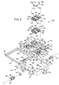
- First enclosure 20 and second enclosure 24 are identical and therefore only first enclosure 20 is described herein in details with reference to Figure 2.
- Enclosure 20 includes a box-like housing 30 having a lid 32 attached thereto by hinges (not shown).
- the housing and lid are preferably formed from 14 gauge steel.
- a sealing member such as a rubber seal 34 is provided at the periphery of the inside face of the lid.
- the base 36 includes 4 upstanding bolts 38, one in each corner area of the housing, only one such bolt being shown in Figure 2.
- a plurality of hinged clamps such as stainless steel clamps 40 are attached to various outside walls of housing 30.
- each clamp 40 When the lid 32 is closed the hooked portion 42 of each clamp 40 can be pivoted to mate with corresponding hooked edges 44 of the lid and the lid pulled firmly in place by further pivoting such clamps 40, in a known manner.
- the enclosure has a first opening 46 and a second opening 48 in opposite walls of the housing 30.
- the enclosure also has fastened thereto a first strain relief grip 50 which is concentric with first opening 46 and a second strain relief grip 52 which is concentric with second opening 48.
- First strain relief grip 50 and second strain relief grip 52 are identical and are fastened to housing 30 in the same manner, and therefore only second strain relief grip 52 is described herein with reference to Figure 3.
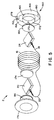
- Second strain relief grip 52 is in the form of what is commonly referred to as a finger grip which includes a tubular structure braided from strands of wire 54 having a collar 56 with an opening 58 therethrough.
- any axial movement of the cable from right to left will cause the braided portion to collapse upon the cable in a known manner to thereby prevent further such axial movement of the cable and thereby provide satisfactory strain relief.
- the strain relief grip is fastened to the housing 30 at opening 48 by first fastening a connector body 60 and metal clad sealing O-ring 62 to the housing 30 at opening 48 by means of locknut 64 and then coupling the strain relief grip to the connector body 60 using a rubber bushing 66 and compression nut 68, in a known manner.
- the strain relief grips control cable arc-of-bend, prevent cable pull-out, and provide a liquid-tight seal.
- Enclosure 20 contains a first splice tray and enclosure 24 contains a second splice tray. Since such first and second splice trays are identical and are fastened to housing 30 in the same manner, only splice tray 70 of enclosure 20 is described herein in details with reference to Figure 2.
- Splice tray 70 can be formed from polypropylene profax and includes a plurality of apertures 72 through which bolts 38 of housing 30 extend, the splice tray thereby being held in place within the housing by means of cap nuts 74 fastened to bolts 38.
- Splice tray 70 includes a base 76.
- the splice tray also includes a first wall 78, a second wall 80, a third wall 82, and a fourth wall 84.
- All of such walls extend away from the base 76, walls 82 and 84 joining walls 78 and 80 at opposite ends thereof. It will be apparent from viewing Figure 2 that when the splice tray 70 is positioned in the housing 20, first wall 78 will be adjacent first opening 46 so that a cut away portion 86 is aligned with opening 46, and second wall 80 will be adjacent second opening 48 so that a cut away portion 88 is aligned with opening 48.
- Third wall 82 includes a first arcuate portion 90 which extends from first wall 78 and a second arcuate portion 92 which extends from second wall 80, arcuate portions 90 and 92 merging at 94.
- fourth wall 84 includes a third arcuate portion 96 opposite first arcuate portion 90 and extending from the first wall 78, and a fourth arcuate portion 98 opposite second arcuate portion 92 and extending from second wall 80, arcuate portions 96 and 98 merging at 100.
- a first hub 102 extends away from base 76 and is spaced from first arcuate portion 90 at 104
- a second hub 106 extends away from base 76 and is spaced from second arcuate portion 92 at 108
- a third hub 110 extends away from base 76 and is spaced from third arcuate portion 96 at 112
- a fourth hub 114 extends away from base 76 and is spaced from fourth arcuate portion 98 at 116.
- hubs 102, 106, 110 and 114 are formed by a plurality of circumferentially spaced arcuate portions of a cylindrical wall having a predetermined bend radius R shown in Figure 4 to accommodate the winding of optical fibers as described herein to minimize undesirable attenuation.
- hub 110 includes such circumferentially spaced arcuate portions 118.
- Each first and second splice tray of first enclosure 20 and second enclosure 24, respectively, also includes at least one splice cradle guide post.
- splice tray 70 includes at least one splice cradle guide post 120 extending away from base 76, four such posts 120 being depicted in the embodiment of Figure 2.
- Each first and second splice tray of first enclosure 20 and second enclosure 24, respectively, further includes at least one splice cradle, and in the preferred embodiment each splice tray includes a plurality of stacked splice cradles.
- splice tray 70 includes a plurality of stacked splice cradles generally designated 112 including a lower splice cradle 124 and an upper splice cradle 126.
- a cover 128 is also provided for the stacked splice cradles.
- splice cradles can be formed from a polypropylene profax material.
- Each splice cradle and cover includes at least one splice cradle guide surface, each of which corresponds to a respective splice cradle guide post 120 to facilitate the proper positioning of the splice cradles and cover relative to the base 76 of the splice tray 70.
- splice cradles 124 and 126 and cover 128 include guide surfaces 130 which mate with respective posts 120.
- splice cradles 124 and 126, and cover 128 include spacers 132 attached to select opposing edges, the spacers being formed from a resilient foam-like material.
- the splice cradles include a plurality of spaced bosses 134 which hold splices in place in a known manner as described herein.
- Means are associated with base 76 and with each splice cradle for attaching the splice cradles and cover together and to the base.
- base 76 and splice cradles 124 and 126 include resilient snap members 136 which snap into place against a corresponding surface of an adjacent splice cradle or cover to hold such splice cradle and cover in place in a known manner as the stacked splice cradles and cover are aligned relative to posts 120 and positioned relative to base 76.
- Labels 138 are also applied to identify respective splice bosses.
- Figure 4 depicts the emergency preterminated cable apparatus thus far described in a field environment during the splicing operation.
- the box-like housings 30 are shown without the lids 32, only one splice cradle is depicted in each housing 30, and only two spaced bosses 134 and no labels 138 are depicted with respect to each such splice cradle.
- like numbers for enclosures 20 and 24 have been primed when applied to enclosure 24.
- the emergency preterminated cable apparatus 2 is for coupling a plurality of constituent first optical fibers 4 extending from an end 6 of a first fiber optic cable 8 to a plurality of constituent second optical fibers 10 extending from an end 12 of a second fiber optic cable 14.
- the fiber end portions have been terminated and coupled to a respective splicing device 142 at the factory in a known manner.
- a second end portion 144 of each optical fiber of the plurality of corresponding constituent optical fibers extends from second end 22 of the cable 16 and includes a respective second splicing device 146.
- the fiber end portions 144 have also been terminated and coupled to a respective splicing device 146 at the factory in a known manner.
- the first enclosure 20 thus contains said first splice tray 70 which includes at least said first splice cradle 126.
- First enclosure 20 has said first opening 46 for permitting said first end portions 140 of said intermediate cable 16 to extend into the first enclosure 20.
- the first splice tray 70 of first enclosure 20 includes at least one means for winding said first fiber end portions 140 and directing each respective first splicing device 142 coupled thereto to splice cradle 126.
- optical fiber end portions 140 are shown in Figure 4 as being wound about hub 102 as many times as is necessary to take up the slack, and then directed towards the splice cradle 126 so that the splicing devices 142 can be attached to the splice cradle 126 by being pinched between a respective set of bosses 134 in a known manner.
- cable 16 will contain 12 to 48 fibers and can go to at least as high as 144 fibers. This explains the presence of hubs 102 and 110, and the use of a plurality of stacked splice cradles 126 as depicted in Figure 2.
- Fiber-dense fiber optic cables some of the individual fiber end portions 140 will be wound about hub 102 and others will be wound about hub 110.
- the ends of such fiber end portions will be coupled to respective splicing devices 142 in the same splice cradle or in different splice cradles in a stack of splice cradles as depicted in Figure 2. It will be understood by those skilled in the art that the present invention contemplates any desired number of splice cradles forming a stack of splice cradles as described herein.
- First enclosure 20 also has said second opening 48 for permitting the plurality of constituent first optical fibers 4 of the first fiber optic cable 8 to extend into enclosure 20.
- the first splice tray 126 further includes at least one other means for winding the plurality of constituent first optical fibers 4 and directing each respective first optical fiber 4 to a splice cradle 126 for splicing to a respective first splicing device 142.
- optical fibers 4 are shown in Figure 4 as being wound about hub 106 as many times as is necessary to take up the slack, and then directed towards the splice cradle 126 so that the fibers 4 can be coupled to a respective splicing device 142 in a known manner.
- fiber end portions 140 in fiber-dense fiber optic cables as discussed above, some of such fibers 4 will be wound about hub 106 and others about hub 114, the ends being coupled to a splicing device 142 in a particular splice cradle in a stack of splice cradles, as required to couple a fiber 4 to the appropriate corresponding fiber end portion 140. It should be noted that although fiber end portions 140 have been preterminated and coupled to respective splicing devices 142 at the factory, the fibers 4 are caused to be passed through opening 48, wound about hub 106 and coupled to splicing device 142 at the site of the portion 8 of the severed cable.
- the other portion 14 of the severed cable is fastened within enclosure 24, the connecting intermediate fiber optic cable 16 thereby effectively rejoining cable 8 to cable 14.
- the optic fibers 4 are shown in Figure 4 as already having been coupled to splicing device 142 by the field technician at the site of the severed cable.
- fibers 10 are shown as not yet having been coupled to respective splicing devices 146.
- Second enclosure 24 contains a second splice tray 70′ including at least one splice cradle 126′.
- Second enclosure 24 has a first opening 46′ for permitting the second end portions 144 of the plurality of corresponding constituent optical fibers of the intermediate cable 16 to extend into the second enclosure 24.
- the second splice tray 70′ of second enclosure 24 includes at least one means for winding said second fiber end portions 144 and directing each respective second splicing device 146 coupled thereto to splice cradle 126′.
- optical fiber end portions 144 are shown in Figure 4 as being wound about hub 102′ to take up the slack, and then directed towards splice cradle 126′ so that the splicing devices 146 can be attached to splice cradle 126′ by being pinched between a respective set of bosses 134′ in a known manner.
- Second enclosure 24 also has a second opening 48′ for permitting the plurality of constituent second optical fibers 10 of the second fiber optical cable 14 to extend into the second enclosure 24.
- the second splice tray 70′ further includes at least one other means for winding the plurality of constituent second optical fibers 10 and directing each respective second optical fiber 10 to a splice cradle 126′ for splicing to a respective second splicing device 146.
- optical fibers 10 are shown in Figure 4 as being wound about hub 106′ to take up the slack, and then directed towards the splice cradle 126′ so that the fibers 10 can be coupled to a respective splicing device 146 in a known manner.
- the second enclosure 24 can include pairs of hubs 102′, 110′ and 106′, 114′ and a stack of stackable splice cradles.
- the fiber end portions 144 of enclosure 24 have been preterminated and coupled to respective splicing devices 146 at the factory.
- the fibers 10 are caused to be passed through opening 48′, wound about hub 106′, and coupled to splicing device 146 at the site of the portion 14 of the severed cable.
- the stick 148 depicted in Figure 2 as being clipped to lid 32 by a clip 150 is removed from the lid and used to remove a splicing device 146 from splice cradle 126′.
- the emergency preterminated cable apparatus 2 includes some form of housing which is readily storable in the vehicle used by the field technician and by means of which the technician can carry the repair equipment to the site of the severed or otherwise damaged fiber optic cable.
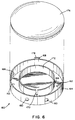
- Figures 5 and 6 depict a preferred form of such a housing 160 for containing the length of intermediate cable 16 and the first enclosure 20 and second enclosure 24.
- Such housing 160 comprises a base 162 having an outer cylindrical wall 164 and a concentric inner cylindrical wall 166 each extending vertically from the base.
- the concentric inner cylindrical wall forms a hub for winding the length of intermediate cable 16 about, such wound cable thereby resting in the space 168 between wall 164 and wall 166.
- the concentric inner cylindrical wall includes an elongated aperture 170 therethrough, the first enclosure 20 and second enclosure 24 being positioned within cavity 172 formed by wall 166. When so positioned within cavity 172, the first end 18 and second end 22 of cable 16 will extend through aperture 170 to a respective enclosure 20 and 24.
- a spacer 174 is positioned in cavity 172 between first enclosure 20 and second enclosure 24, and the housing 160 will include a lid 176, a handle 178 and anti-roll legs 180.
- Spacer 174 can be an open cell foam formed from a polyether grade urethane in a known manner.
- the drum-like housing 160 can be provided with a pop-out circular portion 182 and the lid 176 can be provided with a similar pop-out circular portion 184, shown only in Figure 5.
- the drum-like housing 160 and lid 176 preferably form a fiber drum which is water resistant.
- the damaged section is cut out. For example, ten feet of cable can be cut out on each side of the damaged portion of the cable. Then the optical fibers 4 at end 6 of the remaining portion 8 of the damaged cable are exposed. The fibers 4 are fed into enclosure 20 through opening 48 and the brushing 66 and strain relief grip 52 are slid into position and fastened in place. Select of such fibers 4 are then wound about respective select hubs 106, 114 of enclosure 20.
- a splicing device 142 is then removed from a splice cradle of enclosure 20 using stick 148 and a fiber 4 is spliced thereto. The splicing device 142 is then snapped back into position in the splice cradle.
Landscapes
- Physics & Mathematics (AREA)
- General Physics & Mathematics (AREA)
- Optics & Photonics (AREA)
- Light Guides In General And Applications Therefor (AREA)
- Processing Of Terminals (AREA)
- Mechanical Coupling Of Light Guides (AREA)
Claims (10)
- Ein Notgerät mit vorabgeschlossenem Kabel für den Anschluß einer Mehrzahl Bestandteile bildender erster Optikfasern (4), die sich von einem Ende (6) eines ersten faseroptischen Kabels (8) zu einer Mehrzahl Bestandteile bildender zweiter ausgehender Optikfasern (10) von einem Ende (12) eines zweiten faseroptischen Kabels (14) erstrecken, umfassend:
ein Stück faseroptisches Zwischenkabel (16) mit einem ersten Ende (18) und einem gegenüberliegenden zweiten Ende (22) und einschließlich einer Mehrzahl entsprechender Bestandteile bildender Optikfasern, einem ersten Endteil (140) jeder Optikfaser der besagten Mehrzahl entsprechender Bestandteile bildender Optikfasern ausgehend von dem besagten ersten Ende (18) des besagten Zwischenkabels (16) und einschließlich einer betreffenden ersten Spleißvorrichtung (142) am Ende davon, sowie einem gegenüber befindlichen zweiten Endteil (144) jeder Optikfaser der besagten Mehrzahl entsprechender Bestandteile bildender Optikfasern ausgehend von dem besagten zweiten Ende (22) des besagten Zwischenkabels (16) und einschließlich einer betreffenden Spleißvorrichtung (146) am Ende davon;
ein erstes Gehäuse (20) mit einem ersten Spleißkasten (70), wobei der besagte erste Spleißkasten ( 70) mindestens ein erstes Spleißlager (126) umfaßt, das besagte erste Gehäuse (20) eine erste Öffnung (46) besitzt, die es ermöglicht, daß sich die besagten Endteile (140) der besagten Mehrzahl entsprechender Bestandteile bildender Optikfasern des besagten Zwischenkabels (16) in das besagte Gehäuse erstrecken, der besagte erste Spleißkasten (70) des weiteren mindestens ein Mittel (102) zum Wickeln der besagten Faserendteile (140) und zum Positionieren jeder am Ende davon befindlichen betreffenden ersten Spleißvorrichtung (142) auf besagtem mindestens einem ersten Spleißlager (126) umfaßt, das besagte erste Gehäuse (20) eine zweite Öffnung (48) aufweist, die es ermöglicht, daß sich die besagte Mehrzahl Bestandteile bildender erster Optikfasern (4) des besagten ersten faseroptischen Kabels (8) in das besagte Gehäuse erstreckt, und der besagte erste Spleißkasten (70) des weiteren mindestens ein anderes Mittel (106) zum Wickeln der besagten Mehrzahl Bestandteile bildender erster Optikfasern (4) des besagten ersten Kabels (8) und zum Führen jeder Optikfaser der besagten Mehrzahl Bestandteile bildender erster Optikfasern (4) zu dem besagten mindestens einem ersten Spleißlager (126) zum Spleißen mit einer betreffenden der besagten ersten Spleißvorrichtungen (142) umfaßt; und ein zweites Gehäuse (24) mit einem zweiten Spleißkasten (70′), wobei der beagte zweite Spleißkasten (70′) mindestens ein zweites Spleißlager (126′) umfaßt und das besagte zweite Gehäuse (24) eine erste Öffnung (46′) aufweist, die es ermöglicht, daß sich die besagten zweiten Endteile (144) der besagten Mehrzahl entsprechender Bestandteile bildender Optikfasern des besagten Zwischenkabels (16) in das besagte Gehäuse erstrecken, der besagte zweite Spleißkasten (70′) des weiteren mindestens ein Mittel (102′) zum Wickeln der besagten zweiten Faserendteile (144) und zum Positionieren jeder betreffenden am Ende davon befindlichen zweiten Spleißvorrichtung (146) auf dem besagten mindestens einem zweiten Spleißlager (126′) umfaßt, das besagte zweite Gehäuse (24) eine zweite Öffnung (48′) aufweist, die es ermöglicht, daß sich die Mehrzahl der Bestandteile bildenden zweiten Optikfasern (10) des besagten zweiten faseroptischen Kabels (14) in das besagte Gehäuse erstrecken, und der besagte zweite Spleißkasten (70′) außerdem mindestens ein anderes Mittel (106′) zum Wickeln der besagten Mehrzahl Bestandteile bildender zweiter Optikfasern (10) des besagten zweiten Kabels (14) und zum Führen jeder Optikfaser der besagten Mehrzahl Bestandteile bildender zweiter Optikfasern (10) zu dem besagten mindestens einem zweiten Spleißlager (126′) zum Spleißen mit einer betreffenden der besagten zweiten Spleißvorrichtungen (146) umfaßt. - Das Notgerät mit vorabgeschlossenem Kabel nach Anspruch 1, bei dem der besagte erste Spleißkasten (70) und der besagte zweite Spleißkasten (70′) je eine Grundplatte (76) bzw. (76′) umfassen, sowie eine erste Wand (78), die sich von der besagten Grundplatte weg erstreckt und anschließend an der ersten Öffnung (46, 46′) ist, eine zweite der besagten ersten Wand gegenüberliegende Wand (80), die sich von der besagten Grundplatte weg erstreckt und anschließend an der zweiten Öffnung (48, 48′) ist, eine dritte sich von der besagten Grundplatte weg erstreckende Wand (82), die die besagten ersten und zweiten Wände verbindet und einen von der besagten ersten Wand (78) ausgehenden ersten bogenförmigen Abschnitt (90, 90′) sowie einen zweiten von der besagten zweiten (80) ausgehenden bogenförmigen Abschnitt (92, 92′) umfaßt, und eine vierte der besagten dritten Wand (82) gegenüber befindliche Wand (84), die sich von der besagten Grundplatte weg erstreckt, die besagten ersten und zweiten Wände verbindet und einen dritten dem besagten ersten bogenförmigen Abschnitt (90, 90′) gegenüber befindlichen und von der besagten ersten Wand (78) ausgehenden Abschnitt (96, 96′) sowie einen vierten dem besagten zweiten bogenförmigen Abschnitt (92, 92′) gegenüber befindlichen und von der besagten zweiten Wand (80) ausgehenden bogenförmigen Abschnitt (98, 98′) umfaßt, eine erste Wickelführung (102, 102′), die sich von der besagten Grundplatte weg erstreckt und sich in einem Abstand von dem besagten ersten bogenförmigen Abschnitt (90, 90′) befindet, eine zweite Wickelführung (106, 106′), die sich von der besagten Grundplatte weg erstreckt und sich in einem Abstand von dem besagten zweiten bogenförmigen Abschnitt (92, 92′) befindet, eine dritte Wickelführung (110, 110′), die sich von der besagten Grundplatte weg erstreckt und sich in einem Abstand von dem besagten dritten bogenförmigen Abschnitt (96, 96′) befindet, sowie eine vierte Wickelführung (114,114′), die sich von der besagten Grundplatte weg erstreckt und sich in einem Abstand von dem besagten vierten bogenförmigen Abschnitt (98, 98′) befindet, wobei die besagten ersten Wickelführungen (102, 102′) und dritten Wickelführungen (110, 110′) die besagten Wickel- und Führungsmittel für die betreffenden der besagten Mehrzahl Bestandteile bildender erster Optikfaserendteile (140) und zweiter Optikfaserendteile (144) des besagten faseroptischen Zwischenkabels (16) und die besagten zweiten Wickelführungen (106, 106′) und vierten Wickelführungen (114, 114′) die besagten Wickel und Führungsmittel für die betreffenden der besagten Mehrzahl entsprechender Bestandteile bildender erster und zweiter Optikfasern (4, 10) des besagten ersten faseroptischen Kabels (8) und des besagten zweiten faseroptischen Kabels (14) bilden.
- Das Notgerät mit vorabgeschlossenem Kabel nach Anspruch 2, bei dem jede der besagten Wickelführungen (102, 106, 110, 114, 102′, 106′ 110′, 114′) durch eine Mehrzahl peripher angeordneter bogenförmiger Teile (118) einer zylindrischen Wand mit vorbestimmtem Krümmungsradius gebildet wird.
- Das Notgerät mit vorabgeschlossenem Kabel nach Anspruch 2 oder 3, bei dem der besagte erste bogenförmige Abschnitt (90, 90′) und der besagte zweite bogenförmige Abschnitt (92, 92′) ineinander übergehen und der besagte dritte bogenförmige Abschnitt (96, 96′) und der besagte vierte bogenförmige Abschnitt (98, 98′) ineinander übergehen.
- Das Notgerät mit vorabgeschlossenem Kabel nach einem der Ansprüche 1-4, bei dem das besagte mindestens eine erste Spleißlager (126) eine erste Mehrzahl von übereinander befindlichen Spleißlagern (124, 126) umfaßt und das besagte mindestens eine zweite Spleißlager (126′) eine zweite Mehrzahl übereinander befindlicher Spleißlager (124′, 126′) umfaßt.
- Das Notgerät mit vorabgeschlossenem Kabel nach Anspruch 5, bei dem sowohl das besagte erste Gehäuse (20) als auch das besagte zweite Gehäuse (24) mindestens einen Spleißlagerführungsstift (120) umfaßt, der sich von einer betreffenden Grundplatte (76, 76′) weg erstreckt, wobei des weiteren jedes Spleißlager einer betreffenden Mehrzahl übereinander befindlicher Spleißlager mindestens eine entsprechende Spleißlagerführungsfläche (130) umfaßt.
- Das Notgerät mit vorabgeschlossenem Kabel nach Anspruch 5 oder 6, bei dem sowohl das besagte erste Gehäuse (20) als auch das besagte zweite Gehäuse (24) betreffende Mittel (136) umfaßt, die zwecks Anbringung des betreffenden Spleißlagers an eine betreffende Grundplatte mit einer betreffenden Grundplatte und mit einem betreffenden Spleißlager einer betreffenden Mehrzahl übereinander befindlicher Spleißlager in Verbindung stehen.
- Das Notgerät mit vorabgeschlossenem Kabel nach einem der Ansprüche 1-7, bei dem sowohl das besagte erste Gehäuse (20) als auch das besagte zweite Gehäuse (24) mit einem daran befestigten betreffenden ersten Entspannungsgreifer (50, 50′) versehen ist, wobei jeder der besagten Entspannungsgreifer mit einer betreffenden der besagten ersten Öffnungen (46, 46′) konzentrisch ist und wobei des weiteren sowohl das besagte erste als auch das besagte zweite Gehäuse mit einem daran befestigten betreffenden zweiten Entspannungsgreifer (52, 52′) versehen ist, wobei jeder der besagten Entspannungsgreifer mit einer betreffenden der besagten zweiten Öffnungen (48, 48′) konzentrisch ist.
- Das Notgerät mit vorabgeschlossenem Kabel nach einem der Ansprüche 1-8, wobei dieses des weiteren mit einem Gehäuse (160) zur Aufnahme des besagten Stücks faseroptischen Zwischenkabels (16), des besagten ersten Gehäuses (20) und des besagten zweiten Gehäuses (24) versehen ist.
- Das Notgerät mit vorabgeschlossenem Kabel nach Anspruch 9, bei dem das besagte Gehäuse (160) ein Unterteil (162) mit einer äußeren zylindrischen Wand (164) und einer konzentrischen inneren zylindrischen Wand (166) aufweist, wobei sich jede der besagten Wände senkrecht von der besagten Grundplatte erstreckt und die besagte innere zylindrische Wand eine Wickelführung zum Wickeln des besagten Stückes des besagten faseroptischen Zwischenkabels (16) bildet.
Applications Claiming Priority (2)
| Application Number | Priority Date | Filing Date | Title |
|---|---|---|---|
| US07/204,801 US4846565A (en) | 1988-06-10 | 1988-06-10 | Emergency preterminated cable apparatus |
| US204801 | 1988-06-10 |
Publications (3)
| Publication Number | Publication Date |
|---|---|
| EP0346145A2 EP0346145A2 (de) | 1989-12-13 |
| EP0346145A3 EP0346145A3 (en) | 1990-07-18 |
| EP0346145B1 true EP0346145B1 (de) | 1993-03-10 |
Family
ID=22759492
Family Applications (1)
| Application Number | Title | Priority Date | Filing Date |
|---|---|---|---|
| EP89305867A Expired - Lifetime EP0346145B1 (de) | 1988-06-10 | 1989-06-09 | Behelfsmässige Kabelverbindungsvorrichtung |
Country Status (4)
| Country | Link |
|---|---|
| US (1) | US4846565A (de) |
| EP (1) | EP0346145B1 (de) |
| JP (1) | JPH0229703A (de) |
| ES (1) | ES2039077T3 (de) |
Families Citing this family (16)
| Publication number | Priority date | Publication date | Assignee | Title |
|---|---|---|---|---|
| US5097530A (en) * | 1991-04-04 | 1992-03-17 | Raychem Corporation | Optical fiber enclosure including novel retaining ring |
| IT1247307B (it) * | 1991-05-06 | 1994-12-12 | Sirti Spa | Dispositivo diramatore per cavi a fibre ottiche |
| DE4119829A1 (de) * | 1991-06-15 | 1992-12-17 | Rose Walter Gmbh & Co Kg | Vorrichtung zum aufteilen von lichtwellenleiterkabeln bzw. -adern |
| US5185843A (en) * | 1992-01-28 | 1993-02-09 | At&T Bell Laboratories | Restoration kit for communications cable |
| FR2687800B1 (fr) * | 1992-02-21 | 1994-04-08 | Mars Actel | Cassette adaptable de lovage et d'epissurage de fibres optiques. |
| US5323480A (en) * | 1992-11-25 | 1994-06-21 | Raychem Corporation | Fiber optic splice closure |
| US5708751A (en) * | 1996-04-24 | 1998-01-13 | Tii Industries, Inc. | Optical fiber enclosure system |
| US5892877A (en) * | 1997-06-30 | 1999-04-06 | Tii Industries, Inc. | Optical fiber strain relief system |
| US6382845B1 (en) * | 1999-03-02 | 2002-05-07 | Ameritech Corporation | Fiber optic patch kit and method for using same |
| FR2821934B1 (fr) * | 2001-03-12 | 2004-06-25 | Teem Photonics | Guide de passage pour fibres optiques et boitier de reception de composants optiques equipe d'un tel guide |
| US7689089B2 (en) | 2006-10-11 | 2010-03-30 | Panduit Corp. | Release latch for pre-terminated cassette |
| US20090196563A1 (en) * | 2008-02-01 | 2009-08-06 | Mullsteff David M | Multi-Fiber Optical Patch Cord Breakout Assembly |
| US10379308B2 (en) | 2012-03-19 | 2019-08-13 | Brian D. Coate | Apparatus and method for splicing all-dielectric self-supporting fiber optic cable |
| US9690065B2 (en) | 2014-09-12 | 2017-06-27 | Panduit Corp. | High density fiber enclosure and method |
| US10215944B2 (en) | 2016-06-30 | 2019-02-26 | Panduit Corp. | Modular fiber optic tray |
| SE545433C2 (en) * | 2022-01-31 | 2023-09-12 | Tykoflex Ab | Splicing device |
Family Cites Families (8)
| Publication number | Priority date | Publication date | Assignee | Title |
|---|---|---|---|---|
| FR2517077B1 (fr) * | 1981-11-25 | 1988-01-15 | Ctm | Boite de raccordement pour cables a fibres optiques |
| DE3248003A1 (de) * | 1982-12-24 | 1984-06-28 | Philips Kommunikations Industrie AG, 8500 Nürnberg | Kabelmuffe fuer lichtwellenleiter-verbindungen |
| US4702551A (en) * | 1984-10-11 | 1987-10-27 | Reliance Comm/Tec Corporation | Method and apparatus for handling and storing cabled spliced ends of fiber optics |
| US4666240A (en) * | 1985-02-01 | 1987-05-19 | Amp Incorporated | Splice organizer for optical cable splices |
| US4685764A (en) * | 1985-02-01 | 1987-08-11 | Amp Incorporated | Splice organizer for optical cable splices |
| DE3532312A1 (de) * | 1985-09-11 | 1987-03-12 | Philips Patentverwaltung | Verfahren zur herstellung einer verbindung zwischen zwei optischen leitungen und anordnung zur ausuebung des verfahrens |
| US4728171A (en) * | 1986-10-20 | 1988-03-01 | Amphenol Corporation | System for use in temporary repair of multiple fiber cable |
| GB8805017D0 (en) * | 1988-03-02 | 1988-03-30 | British Telecomm | Splice tray |
-
1988
- 1988-06-10 US US07/204,801 patent/US4846565A/en not_active Expired - Fee Related
-
1989
- 1989-06-07 JP JP1143216A patent/JPH0229703A/ja active Pending
- 1989-06-09 EP EP89305867A patent/EP0346145B1/de not_active Expired - Lifetime
- 1989-06-09 ES ES198989305867T patent/ES2039077T3/es not_active Expired - Lifetime
Also Published As
| Publication number | Publication date |
|---|---|
| EP0346145A2 (de) | 1989-12-13 |
| US4846565A (en) | 1989-07-11 |
| ES2039077T3 (es) | 1993-08-16 |
| JPH0229703A (ja) | 1990-01-31 |
| EP0346145A3 (en) | 1990-07-18 |
Similar Documents
| Publication | Publication Date | Title |
|---|---|---|
| EP0346145B1 (de) | Behelfsmässige Kabelverbindungsvorrichtung | |
| US5825964A (en) | Optical fiber splice case with cross connect feature | |
| US6192180B1 (en) | Tray for splicing optical ribbon fibers | |
| US6795633B2 (en) | Method and apparatus for handling optical components | |
| US5189725A (en) | Optical fiber closure | |
| CA2196115C (en) | Apparatus for housing a linearized optical fiber amplifier | |
| US5793920A (en) | Method and apparatus for anchoring an optical fiber cable | |
| RU2164357C2 (ru) | Устройство для распределения сростков оптических волокон | |
| US5185843A (en) | Restoration kit for communications cable | |
| US6507691B1 (en) | Fiber optic splice organizer with splicing tray and associated method | |
| US20100092147A1 (en) | Optical fiber cable retention device | |
| WO2008118927A1 (en) | Splice apparatus for optical fiber | |
| WO1997012268A1 (en) | Fiber optic cable splice closure | |
| US5142661A (en) | Fiber optic cable splice support and routing guide | |
| NZ264582A (en) | Stackable optical fibre tube breakout: fibre bundle division | |
| US20220137315A1 (en) | Track device for a telecommunications product | |
| US20210149142A1 (en) | Preparation of fiber optic cables for duct applications | |
| MX2007009578A (es) | Cabeza modular de cables para redes opticas. | |
| CN1133639A (zh) | 光纤编排器 | |
| JP3293088B2 (ja) | 架空光ファイバケーブル接続用収納器および作業台 | |
| US4556206A (en) | Splice work tray assembly | |
| JP3134684B2 (ja) | 光ファイバ接続部用固定装置 | |
| GB2283373A (en) | Breakout | |
| JP2004102073A (ja) | 光ケーブル接続用クロージャ |
Legal Events
| Date | Code | Title | Description |
|---|---|---|---|
| PUAI | Public reference made under article 153(3) epc to a published international application that has entered the european phase |
Free format text: ORIGINAL CODE: 0009012 |
|
| AK | Designated contracting states |
Kind code of ref document: A2 Designated state(s): ES FR GB NL |
|
| PUAL | Search report despatched |
Free format text: ORIGINAL CODE: 0009013 |
|
| AK | Designated contracting states |
Kind code of ref document: A3 Designated state(s): ES FR GB NL |
|
| 17P | Request for examination filed |
Effective date: 19900912 |
|
| 17Q | First examination report despatched |
Effective date: 19920529 |
|
| RAP1 | Party data changed (applicant data changed or rights of an application transferred) |
Owner name: GTE CONTROL DEVICES INCORPORATED |
|
| GRAA | (expected) grant |
Free format text: ORIGINAL CODE: 0009210 |
|
| AK | Designated contracting states |
Kind code of ref document: B1 Designated state(s): ES FR GB NL |
|
| ET | Fr: translation filed | ||
| PGFP | Annual fee paid to national office [announced via postgrant information from national office to epo] |
Ref country code: GB Payment date: 19930528 Year of fee payment: 5 |
|
| PGFP | Annual fee paid to national office [announced via postgrant information from national office to epo] |
Ref country code: ES Payment date: 19930601 Year of fee payment: 5 |
|
| PGFP | Annual fee paid to national office [announced via postgrant information from national office to epo] |
Ref country code: FR Payment date: 19930629 Year of fee payment: 5 |
|
| PGFP | Annual fee paid to national office [announced via postgrant information from national office to epo] |
Ref country code: NL Payment date: 19930630 Year of fee payment: 5 |
|
| REG | Reference to a national code |
Ref country code: GB Ref legal event code: 732E |
|
| REG | Reference to a national code |
Ref country code: FR Ref legal event code: TP |
|
| NLS | Nl: assignments of ep-patents |
Owner name: GTE CONTROL DEVICES OF PUERTO RICO INCORPORATED TE |
|
| PLBE | No opposition filed within time limit |
Free format text: ORIGINAL CODE: 0009261 |
|
| STAA | Information on the status of an ep patent application or granted ep patent |
Free format text: STATUS: NO OPPOSITION FILED WITHIN TIME LIMIT |
|
| 26N | No opposition filed | ||
| REG | Reference to a national code |
Ref country code: GB Ref legal event code: 732E |
|
| REG | Reference to a national code |
Ref country code: FR Ref legal event code: TP |
|
| REG | Reference to a national code |
Ref country code: ES Ref legal event code: PC2A Owner name: SIECOR PUERTO RICO, INC. |
|
| PG25 | Lapsed in a contracting state [announced via postgrant information from national office to epo] |
Ref country code: GB Effective date: 19940609 |
|
| PG25 | Lapsed in a contracting state [announced via postgrant information from national office to epo] |
Ref country code: ES Free format text: LAPSE BECAUSE OF NON-PAYMENT OF DUE FEES Effective date: 19940610 |
|
| PG25 | Lapsed in a contracting state [announced via postgrant information from national office to epo] |
Ref country code: NL Effective date: 19950101 |
|
| GBPC | Gb: european patent ceased through non-payment of renewal fee |
Effective date: 19940609 |
|
| NLV4 | Nl: lapsed or anulled due to non-payment of the annual fee | ||
| PG25 | Lapsed in a contracting state [announced via postgrant information from national office to epo] |
Ref country code: FR Effective date: 19950228 |
|
| REG | Reference to a national code |
Ref country code: FR Ref legal event code: ST |
|
| REG | Reference to a national code |
Ref country code: ES Ref legal event code: FD2A Effective date: 19990503 |