EP0345181A1 - Detektions- und Stosswiedererkennungsverfahren und -vorrichtung durch Impedanzänderungsmessung - Google Patents
Detektions- und Stosswiedererkennungsverfahren und -vorrichtung durch Impedanzänderungsmessung Download PDFInfo
- Publication number
- EP0345181A1 EP0345181A1 EP89430012A EP89430012A EP0345181A1 EP 0345181 A1 EP0345181 A1 EP 0345181A1 EP 89430012 A EP89430012 A EP 89430012A EP 89430012 A EP89430012 A EP 89430012A EP 0345181 A1 EP0345181 A1 EP 0345181A1
- Authority
- EP
- European Patent Office
- Prior art keywords
- impedance
- sensor
- variation
- layers
- electronic system
- Prior art date
- Legal status (The legal status is an assumption and is not a legal conclusion. Google has not performed a legal analysis and makes no representation as to the accuracy of the status listed.)
- Withdrawn
Links
Images
Classifications
-
- A—HUMAN NECESSITIES
- A63—SPORTS; GAMES; AMUSEMENTS
- A63B—APPARATUS FOR PHYSICAL TRAINING, GYMNASTICS, SWIMMING, CLIMBING, OR FENCING; BALL GAMES; TRAINING EQUIPMENT
- A63B71/00—Games or sports accessories not covered in groups A63B1/00 - A63B69/00
- A63B71/06—Indicating or scoring devices for games or players, or for other sports activities
- A63B71/0605—Decision makers and devices using detection means facilitating arbitration
-
- G—PHYSICS
- G01—MEASURING; TESTING
- G01D—MEASURING NOT SPECIALLY ADAPTED FOR A SPECIFIC VARIABLE; ARRANGEMENTS FOR MEASURING TWO OR MORE VARIABLES NOT COVERED IN A SINGLE OTHER SUBCLASS; TARIFF METERING APPARATUS; MEASURING OR TESTING NOT OTHERWISE PROVIDED FOR
- G01D5/00—Mechanical means for transferring the output of a sensing member; Means for converting the output of a sensing member to another variable where the form or nature of the sensing member does not constrain the means for converting; Transducers not specially adapted for a specific variable
- G01D5/12—Mechanical means for transferring the output of a sensing member; Means for converting the output of a sensing member to another variable where the form or nature of the sensing member does not constrain the means for converting; Transducers not specially adapted for a specific variable using electric or magnetic means
- G01D5/14—Mechanical means for transferring the output of a sensing member; Means for converting the output of a sensing member to another variable where the form or nature of the sensing member does not constrain the means for converting; Transducers not specially adapted for a specific variable using electric or magnetic means influencing the magnitude of a current or voltage
- G01D5/16—Mechanical means for transferring the output of a sensing member; Means for converting the output of a sensing member to another variable where the form or nature of the sensing member does not constrain the means for converting; Transducers not specially adapted for a specific variable using electric or magnetic means influencing the magnitude of a current or voltage by varying resistance
- G01D5/165—Mechanical means for transferring the output of a sensing member; Means for converting the output of a sensing member to another variable where the form or nature of the sensing member does not constrain the means for converting; Transducers not specially adapted for a specific variable using electric or magnetic means influencing the magnitude of a current or voltage by varying resistance by relative movement of a point of contact or actuation and a resistive track
-
- G—PHYSICS
- G01—MEASURING; TESTING
- G01D—MEASURING NOT SPECIALLY ADAPTED FOR A SPECIFIC VARIABLE; ARRANGEMENTS FOR MEASURING TWO OR MORE VARIABLES NOT COVERED IN A SINGLE OTHER SUBCLASS; TARIFF METERING APPARATUS; MEASURING OR TESTING NOT OTHERWISE PROVIDED FOR
- G01D5/00—Mechanical means for transferring the output of a sensing member; Means for converting the output of a sensing member to another variable where the form or nature of the sensing member does not constrain the means for converting; Transducers not specially adapted for a specific variable
- G01D5/12—Mechanical means for transferring the output of a sensing member; Means for converting the output of a sensing member to another variable where the form or nature of the sensing member does not constrain the means for converting; Transducers not specially adapted for a specific variable using electric or magnetic means
- G01D5/14—Mechanical means for transferring the output of a sensing member; Means for converting the output of a sensing member to another variable where the form or nature of the sensing member does not constrain the means for converting; Transducers not specially adapted for a specific variable using electric or magnetic means influencing the magnitude of a current or voltage
- G01D5/24—Mechanical means for transferring the output of a sensing member; Means for converting the output of a sensing member to another variable where the form or nature of the sensing member does not constrain the means for converting; Transducers not specially adapted for a specific variable using electric or magnetic means influencing the magnitude of a current or voltage by varying capacitance
-
- G—PHYSICS
- G01—MEASURING; TESTING
- G01L—MEASURING FORCE, STRESS, TORQUE, WORK, MECHANICAL POWER, MECHANICAL EFFICIENCY, OR FLUID PRESSURE
- G01L5/00—Apparatus for, or methods of, measuring force, work, mechanical power, or torque, specially adapted for specific purposes
- G01L5/14—Apparatus for, or methods of, measuring force, work, mechanical power, or torque, specially adapted for specific purposes for measuring the force of explosions; for measuring the energy of projectiles
-
- G—PHYSICS
- G01—MEASURING; TESTING
- G01R—MEASURING ELECTRIC VARIABLES; MEASURING MAGNETIC VARIABLES
- G01R27/00—Arrangements for measuring resistance, reactance, impedance, or electric characteristics derived therefrom
- G01R27/02—Measuring real or complex resistance, reactance, impedance, or other two-pole characteristics derived therefrom, e.g. time constant
-
- G—PHYSICS
- G08—SIGNALLING
- G08B—SIGNALLING OR CALLING SYSTEMS; ORDER TELEGRAPHS; ALARM SYSTEMS
- G08B13/00—Burglar, theft or intruder alarms
- G08B13/22—Electrical actuation
- G08B13/26—Electrical actuation by proximity of an intruder causing variation in capacitance or inductance of a circuit
-
- A—HUMAN NECESSITIES
- A63—SPORTS; GAMES; AMUSEMENTS
- A63B—APPARATUS FOR PHYSICAL TRAINING, GYMNASTICS, SWIMMING, CLIMBING, OR FENCING; BALL GAMES; TRAINING EQUIPMENT
- A63B71/00—Games or sports accessories not covered in groups A63B1/00 - A63B69/00
- A63B71/06—Indicating or scoring devices for games or players, or for other sports activities
- A63B71/0605—Decision makers and devices using detection means facilitating arbitration
- A63B2071/0611—Automatic tennis linesmen, i.e. in-out detectors
Definitions
- the present invention relates to methods and devices for detecting and recognizing impact by measuring variation in impedance.
- the technical sector of the invention is the manufacture of sensors associated with a measurement and calculation device, allowing the detection, and above all the recognition of impacts on any surface equipped with a sensor.
- One of the main applications of the invention relates to all the fields of surveillance of premises to trigger any type of alert, upon detection of a predetermined intrusion into these premises, and those of fluid mechanics, and the realization of artificial skins.
- Another application is its use in the sports field, each time that one wishes to detect for example the striking of a ball on or outside a determined line like in tennis, without being disturbed by other type of impact, like those caused by players' feet.
- Each of the corresponding methods and devices responds to a given use, taking into account the desired detection criteria, and each has its own reliability and quality.
- to detect impacts essentially, either simple systems with contacts in all or nothing which therefore only triggers a determined threshold of displacement of said contact, or measurement sensors, which allow to try to know as well as possible the variation of a physical parameter such as pressure, in order to have a quantitative measure of impact from which various actions can be triggered.
- Patent application NO. 75 / 34.225 filed on 05 November 1975 by the NATIONAL DEVELOPMENT AGENCY FOR RESEARCH - ANVAR describes a touch sensor, with the aim of creating an "artificial skin", comprising a multitude of measurement electrodes and conductive elements , nested one inside the other and embedded in a material whose electrical conductivity depends on its compression.
- the present invention falls into this category of devices and, more particularly to those intended for detections, on surfaces, of impacts and for the recognition of these impacts to trigger selective actions.
- One of the problems posed is in fact to be able to detect and select in particular on a given surface, at least one type of impact that has been defined beforehand and only this, and this in any circumstance and whatever the state of said surface at the time of impact.
- a solution to the problem posed is a method for detecting and recognizing the impact received by a surface, comprising the following operations: - There are at least two layers of materials, electrical conductors in contact with each other, to form a sensor, which covers said surface; - each of the external layers is connected to a terminal of an electronic system comprising at least one constant current generator then traversing said layers, a microprocessor associated at least with a memory and allowing in particular the measurement of the potential difference at the terminals said sensor, and various input-output interfaces; - the speed of variation of the impedance of this is calculated sensor which changes when it is subjected to a physical phenomenon different from that of its initial situation, which speed of variation of impedance is directly proportional to the derivative of the measured potential difference; in a first learning phase, the value of the sensor impedance is said to be at rest and corresponding to a given initial situation, and in each variation of this impedance in the phase of use, said microprocessor having been previously programmed for this, sends a given
- an impact detection and recognition device received by a surface of the type comprising a pressure sensor by measuring the impedance of said sensor associated with an electronic system allowing said measurement, in which said sensor is consisting of at least two layers of electrically conductive materials, in contact and arranged for example parallel to each other, covering said surface, and the external layers of which are each connected from at least any point on their surfaces to a terminal of said electronic system.
- This electronic system comprises at least one constant current generator then traversing said layers, a microprocessor associated with at least one memory and allowing in particular the measurement of the potential difference at the edge of said sensor, the calculation of the derivative of this potential difference , the comparison of the result obtained with derivative values stored in said memory and associated with a type of impact determined previously, and the emission of signal through at least one output interface, when said comparison corresponds to a choice of detection and wanted recognition.
- an impact detection and recognition method comprises the following operations: - during said first learning phase, each said speed of variation and the nature of the phenomenon then known which caused this variation and which is specific to it for said surface are associated and stored in said system memory; - we establish a classification and a selection among all the phenomena which can cause a variation of the impedance, and we program said microprocessor so that in the use phase, it sends a given signal to an output interface for only certain speeds variation in this impedance.
- the result is new methods and devices for detecting impacts by measuring impedance variation speed, the characteristics of which make it possible to satisfy various applications, whatever the environmental conditions thereof.
- the main advantage of the present invention is that it allows a qualitative measurement of the phenomenon and not a quantitative one. Indeed, currently, there is no sensor that can react to impacts and discriminate them.
- the device according to the invention described below is not a measurement sensor in the proper sense of the term.
- the present invention can have multiple applications as a switch, contact and detection in fields such as surveillance, security, stock management, sports, fluid mechanics, robotics (artificial skin), acoustics etc ...
- the sensors according to the invention can operate in any atmosphere and even in water, since they do not present any risk of electrocution.
- the shape of the sensor does not matter for the operation of the process: it can even be envisaged that the shape adaptation may be made by the end user who adapts said sensor to the surface that he determines, both in size and in formatting thereon, since in the present invention, the initial state which determines the value of the impedance of the said sensor at rest, does not intervene in the analysis of the variation thereof.
- the device can be installed on any support and surface.
- the information collected is then the unquantified image of the phenomenon, but whose qualitative characteristics determined by one or more values of derivatives, associated or not with a duration and with one or more accelerations, make it possible to classify said phenomenon in a way certain and therefore to recognize it, to select it in the middle of others and to trigger any desired action according to the chosen use.
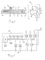
- FIG. 1 represents a sectional view of a sensor 6 according to the invention, placed on any surface 8 and connected to an electronic system 10, an example of a more detailed diagram of which is described in FIG. 2.
- the sensor 6 consists essentially of at least two layers 1 and 2 of conductive materials of any type, compressible or not, flexible or not, and in contact with each other.
- the layers of material are preferably arranged parallel to one another and cover the surface 8 on which the sensor must detect the impacts and recognize them.
- said layers are flexible to match the shape of said surface and their external dimension can be arbitrary.
- these layers are separated by a layer 5 of material.
- that of intermediate layer 5 can be: - either conductive, flexible, compressible, deformable and elastic, making it easier to differentiate objects 9, which strike the upper face of the sensor 6, at an impact point 19, and thus compress more or less in value and speed this intermediate layer 5, thus creating a variation in impedance easier to detect and measure; - Is insulating, flexible and perforated and can then allow geographic discrimination of the location of the point of impact 19 on the surface of the sensor.
- this material of the intermediate layer 5 can be as above, and even non-compressible, since the compression then affects the outer layers.
- a sensor in another embodiment, can be formed by filling a sheath of any shape with several distinct pieces of conductive material, such as a piece of foam, constituting as many external and intermediate layers, the ends of which are connected to the electronic system 10.
- the conductive layers 1 and 2 are each connected from at least any point 71 and 72 respectively of their surface, by contacts of any known type such as rivets, screw terminals, soldering etc ..., to conductors 4, themselves connected to an electronic system 10.
- said points 71 and 72 are as far apart as possible relative to each other, because the more they are distant from each other, the greater the sensitivity of the device.
- these conductive layers 1 and 2 themselves constitute the envelope of the sensor 6, and in another variant, these layers are enclosed and covered in a flexible protective envelope 3, the ends and edges of which are closed by any means, said layers being able to be integral or not with this envelope.
- the thickness of these layers and envelopes can be any, but preferably thin enough, to constitute a fairly flat and therefore discreet sensor.
- Said electronic system 10 comprises at least one constant current generator 11, so as not to be influenced by the length of the conductors 4 and which, for example produces a very low current of the order of 20 mA and even less.
- the role of the microprocessor is to calculate this derivative at any time, and said memory 13, or another, also contains all the application program which, in the use phase, uses the result of the calculation and compares it to one or more thresholds fixed or configured during the learning phase, in order to trigger or not the desired action.
- the program initializes the system and it is also possible after any detection of a variation in the sensor impedance, when it then always takes the same derivative values for a determined minimum duration, to program the microprocessor 12 so that it takes as the new value of the impedance of the sensor at rest, that corresponding to its zero derivative value, and that it then detects only the variations of impedance created by a new impact which produces a different derivative of the above values.
- said value of the reference impedance of the sensor considered to be at rest at a given instant can be reactivated at given time intervals such as a few microseconds, corresponding to a program cycle of said microprocessor 12 and adapted to a given application.
- the method according to the invention uses the calculation of the derivative of the impedance value and not its absolute value: thus any slow variation such as due to the temperature or to the hygrometry, induces a very weak derivative, which will be below any threshold corresponding to an impact, and will not trigger, if desired, action.
- FIG. 2 is a more detailed diagram of the principle of what an electronic system 10 can be, as presented in FIG. 1 and very complete, for any use according to the invention.
- microprocessor 12 which can be for example CPU type, operating at 4 MHz and 8 bits, and which can be controlled by a supervisor 17, associated with a clock.
- This microprocessor is connected by a central bus 20, making it possible then to add, if necessary, various other expansion cards, to specific cards, each corresponding to a function of the system: first of all, there are memory cards 13, of which the at least one can receive the program according to the method of the invention and another at least the data for comparing the derivatives of the impedances associated with the corresponding and reference impacts.
- the bus 20 is also connected to a decoding card 21, possibly necessary for certain input and output information, and to a baud generator 18.
- the constant current generator 11 can be a digital analog converter, controlled by the microprocessor and providing the sensor 6, on one of its output channels, with a constant current supply equal for example to 20 mA.
- a digital analog converter 141 collects the voltage variation at the edge of the sensor 6 and transmits it to the microprocessor 12, for calculation of the derivative and comparison then possible action through various output interfaces 15, to external actuators 16. These output interfaces can generate strong currents to act on relays and themselves understand a buffer memory capacity.
- Other input cards 14 can be managed by the same system and receive information from other external sensors, in particular, one of said cards 144 can be connected to a simple sensor acting in all or nothing like a counter, which sensor can be produced according to the description of the invention above, which can then be used directly if this is sufficient for the impedance and no longer its speed or derivative.
- This configuration of electronic system 10 can thus be suitable and be associated with any type of detection and action, including in particular those according to the method of the invention, which method can be operated with a single electronic system 10, connected to several sensors. and devices according to the preceding description.
Landscapes
- Physics & Mathematics (AREA)
- General Physics & Mathematics (AREA)
- Health & Medical Sciences (AREA)
- General Health & Medical Sciences (AREA)
- Physical Education & Sports Medicine (AREA)
- Force Measurement Appropriate To Specific Purposes (AREA)
- Measurement Of Resistance Or Impedance (AREA)
- Investigating Or Analyzing Materials By The Use Of Electric Means (AREA)
- Alarm Systems (AREA)
- Testing Or Calibration Of Command Recording Devices (AREA)
Applications Claiming Priority (2)
| Application Number | Priority Date | Filing Date | Title |
|---|---|---|---|
| FR8807319A FR2632069B1 (fr) | 1988-05-30 | 1988-05-30 | Capteur de detection par vitesse de variation d'impedance ou par variation d'impedance |
| FR8807319 | 1988-05-30 |
Publications (1)
| Publication Number | Publication Date |
|---|---|
| EP0345181A1 true EP0345181A1 (de) | 1989-12-06 |
Family
ID=9366845
Family Applications (1)
| Application Number | Title | Priority Date | Filing Date |
|---|---|---|---|
| EP89430012A Withdrawn EP0345181A1 (de) | 1988-05-30 | 1989-05-19 | Detektions- und Stosswiedererkennungsverfahren und -vorrichtung durch Impedanzänderungsmessung |
Country Status (5)
| Country | Link |
|---|---|
| US (1) | US4990897A (de) |
| EP (1) | EP0345181A1 (de) |
| JP (1) | JPH02118455A (de) |
| AU (1) | AU3513289A (de) |
| FR (1) | FR2632069B1 (de) |
Cited By (1)
| Publication number | Priority date | Publication date | Assignee | Title |
|---|---|---|---|---|
| EP0559634A1 (de) * | 1992-03-02 | 1993-09-08 | Hoerbiger Ventilwerke Aktiengesellschaft | Wegmesseinrichtung |
Families Citing this family (8)
| Publication number | Priority date | Publication date | Assignee | Title |
|---|---|---|---|---|
| US5471192A (en) * | 1994-01-24 | 1995-11-28 | Dash; Glen | Sound producing device stimulated by petting |
| US6598485B1 (en) * | 2000-11-24 | 2003-07-29 | Sinotech Engineering Consultants, Inc. | Method and device for evaluating quality of concrete structures |
| US20060287140A1 (en) * | 2005-06-16 | 2006-12-21 | Brandt Richard A | Automated line calling system |
| FI20075775A0 (fi) * | 2007-10-31 | 2007-10-31 | A4Sp Technologies Ltd | Järjestelmä urheilusuoritusta varten |
| US7772960B2 (en) * | 2007-11-27 | 2010-08-10 | Interlink Electronics, Inc. | Pre-loaded force sensing resistor and method |
| DE102011078746A1 (de) * | 2011-07-06 | 2013-01-10 | Robert Bosch Gmbh | Abstands- und Typenbestimmung von Flugzeugen während des Andockens an das Gate |
| US10500471B2 (en) * | 2013-05-17 | 2019-12-10 | CNOWire, Inc. | Impedance-based impact determination and scoring |
| CN114111549A (zh) * | 2021-11-30 | 2022-03-01 | 北京清航紫荆装备科技有限公司 | 膜航天器及其撞击破损的检测电路和方法 |
Citations (5)
| Publication number | Priority date | Publication date | Assignee | Title |
|---|---|---|---|---|
| DE2529475A1 (de) * | 1975-07-02 | 1977-01-13 | Klaus Dr Nicol | Vorrichtung zum zeitabhaengigen messen physikalischer groessen |
| FR2344006A1 (fr) * | 1976-03-12 | 1977-10-07 | Kavlico Corp | Transducteur de pression capacitif et procede de fabrication d'un tel transducteur |
| GB2013434A (en) * | 1978-01-30 | 1979-08-08 | Exxon Research Engineering Co | Method and apparatus for compensating a sensor |
| FR2417887A1 (fr) * | 1978-02-15 | 1979-09-14 | Bendix Corp | Ensemble comportant un capteur capacitif et un circuit de demodulation |
| DE8706280U1 (de) * | 1987-05-01 | 1987-06-19 | Sie Sensorik Industrie-Elektronik Gmbh, 6806 Viernheim, De |
Family Cites Families (3)
| Publication number | Priority date | Publication date | Assignee | Title |
|---|---|---|---|---|
| US4062008A (en) * | 1976-02-09 | 1977-12-06 | Nils Jeppson | System for selective detection and indication of impacts upon a base surface |
| US4289035A (en) * | 1978-02-15 | 1981-09-15 | The Bendix Corporation | Compensated capacitive transducer demodulator circuit |
| US4855711A (en) * | 1987-06-29 | 1989-08-08 | Sensor Science | Impact detection apparatus |
-
1988
- 1988-05-30 FR FR8807319A patent/FR2632069B1/fr not_active Expired - Lifetime
-
1989
- 1989-05-19 EP EP89430012A patent/EP0345181A1/de not_active Withdrawn
- 1989-05-24 AU AU35132/89A patent/AU3513289A/en not_active Abandoned
- 1989-05-24 US US07/356,796 patent/US4990897A/en not_active Expired - Fee Related
- 1989-05-30 JP JP1137334A patent/JPH02118455A/ja active Pending
Patent Citations (5)
| Publication number | Priority date | Publication date | Assignee | Title |
|---|---|---|---|---|
| DE2529475A1 (de) * | 1975-07-02 | 1977-01-13 | Klaus Dr Nicol | Vorrichtung zum zeitabhaengigen messen physikalischer groessen |
| FR2344006A1 (fr) * | 1976-03-12 | 1977-10-07 | Kavlico Corp | Transducteur de pression capacitif et procede de fabrication d'un tel transducteur |
| GB2013434A (en) * | 1978-01-30 | 1979-08-08 | Exxon Research Engineering Co | Method and apparatus for compensating a sensor |
| FR2417887A1 (fr) * | 1978-02-15 | 1979-09-14 | Bendix Corp | Ensemble comportant un capteur capacitif et un circuit de demodulation |
| DE8706280U1 (de) * | 1987-05-01 | 1987-06-19 | Sie Sensorik Industrie-Elektronik Gmbh, 6806 Viernheim, De |
Non-Patent Citations (2)
| Title |
|---|
| ELECTRONIC ENGINEERING, vol. 45, no. 540, février 1973, page 27; D.W. RUSSELL: "Detecting capacitance changes in transducers" * |
| JOURNAL OF THE AUDIO ENGINEERING SOCIETY, vol. 33, no. 6, juin 1985, pages 430-435, New York, US; J.A.M. CATRYSSE: "On the design of some feedback circuits for loudspeakers" * |
Cited By (1)
| Publication number | Priority date | Publication date | Assignee | Title |
|---|---|---|---|---|
| EP0559634A1 (de) * | 1992-03-02 | 1993-09-08 | Hoerbiger Ventilwerke Aktiengesellschaft | Wegmesseinrichtung |
Also Published As
| Publication number | Publication date |
|---|---|
| JPH02118455A (ja) | 1990-05-02 |
| US4990897A (en) | 1991-02-05 |
| FR2632069B1 (fr) | 1990-12-14 |
| AU3513289A (en) | 1989-11-30 |
| FR2632069A1 (fr) | 1989-12-01 |
Similar Documents
| Publication | Publication Date | Title |
|---|---|---|
| EP1941475B1 (de) | Verfahren zur verarbeitung von beschleunigungsmessungen, beschleunigungsaufnehmer und mit derartigen aufnehmern ausgestattetes alarmsystem | |
| FR2511796A1 (fr) | Dispositif d'affichage a detection de contact et procede de localisation d'un contact capacitif | |
| EP2431911B1 (de) | Schutzvorrichtung für einen Stecker und ein Kommunikationskabel eines Speicherkartenlesegerätes | |
| EP0345181A1 (de) | Detektions- und Stosswiedererkennungsverfahren und -vorrichtung durch Impedanzänderungsmessung | |
| FR2785046A1 (fr) | Dispositif de mesure reposant sur la mesure indirecte de la permittivite | |
| EP2030143B1 (de) | Einrichtung zur abschirmung vor störungen aus elektrischen geräten | |
| WO2010037988A1 (fr) | Procede et dispositif de determination non intrusive de la puissance electrique consommee par une installation, par analyse de transitoires de charge. | |
| FR2964772A1 (fr) | Dispositif de protection d'un circuit imprime electronique. | |
| WO2003042944A1 (fr) | Dispositif de securite filaire pour la detection du vol d'un objet a proteger et procede de fonctionnement. | |
| EP3086910A1 (de) | Stossdetektionssystem für robotische vorrichtung | |
| FR3053122A1 (fr) | Dispositif de detection d'un arc electrique a partir de sa signature acoustique | |
| EP0231549A1 (de) | Geschützte Umfassung mit elektrischem Schalter und ihre Anwendung | |
| EP2548236A2 (de) | Detektor für mechanische belastung | |
| WO2019186050A1 (fr) | Dispositif informatique de detection de troubles du rythme cardiaque | |
| FR2661753A1 (fr) | Procede pour l'amelioration de la precision de detecteurs d'impedance dans des radiosondes. | |
| FR3095062A1 (fr) | Carte à puce comportant un capteur d’empreintes digitales | |
| WO2019102130A1 (fr) | Dispositif de commande, pour outil motorisé et outil sécurisé comprenant un tel dispositif de commande | |
| EP0772851B1 (de) | Feueralarmvorrichtung mit analogem sensor | |
| EP2062192A1 (de) | Antieindringsystem zum schutz elektronischer komponenten | |
| EP3893727B1 (de) | Vorrichtung zur messung der therapeutischen einhaltung des tragens eines textilartikels durch einen patienten, instrumentierter artikel mit solch einer vorrichtung und messverfahren | |
| US20220412836A1 (en) | Low power memristive vacuum sensor | |
| FR2485774A1 (fr) | Detecteur de position d'un organe mobile notamment a des fins de protection | |
| FR2876480A1 (fr) | Systeme et cable de detection d'intrusion | |
| EP2820731A1 (de) | Verfahren und vorrichtung zur überwachung einer gasisolationskammer | |
| FR2571888A1 (fr) | Dispositif pour la representation graphique du deplacement d'un arc electrique produit dans la chambre de coupure d'un dispositif de commutation |
Legal Events
| Date | Code | Title | Description |
|---|---|---|---|
| PUAI | Public reference made under article 153(3) epc to a published international application that has entered the european phase |
Free format text: ORIGINAL CODE: 0009012 |
|
| AK | Designated contracting states |
Kind code of ref document: A1 Designated state(s): AT BE CH DE ES FR GB GR IT LI LU NL SE |
|
| 17P | Request for examination filed |
Effective date: 19900605 |
|
| 17Q | First examination report despatched |
Effective date: 19920717 |
|
| STAA | Information on the status of an ep patent application or granted ep patent |
Free format text: STATUS: THE APPLICATION IS DEEMED TO BE WITHDRAWN |
|
| 18D | Application deemed to be withdrawn |
Effective date: 19921203 |