EP0345181A1 - Process and appliance for detecting and recognizing impact by measuring the impedance variation - Google Patents
Process and appliance for detecting and recognizing impact by measuring the impedance variation Download PDFInfo
- Publication number
- EP0345181A1 EP0345181A1 EP89430012A EP89430012A EP0345181A1 EP 0345181 A1 EP0345181 A1 EP 0345181A1 EP 89430012 A EP89430012 A EP 89430012A EP 89430012 A EP89430012 A EP 89430012A EP 0345181 A1 EP0345181 A1 EP 0345181A1
- Authority
- EP
- European Patent Office
- Prior art keywords
- impedance
- sensor
- variation
- layers
- electronic system
- Prior art date
- Legal status (The legal status is an assumption and is not a legal conclusion. Google has not performed a legal analysis and makes no representation as to the accuracy of the status listed.)
- Withdrawn
Links
Images
Classifications
-
- A—HUMAN NECESSITIES
- A63—SPORTS; GAMES; AMUSEMENTS
- A63B—APPARATUS FOR PHYSICAL TRAINING, GYMNASTICS, SWIMMING, CLIMBING, OR FENCING; BALL GAMES; TRAINING EQUIPMENT
- A63B71/00—Games or sports accessories not covered in groups A63B1/00 - A63B69/00
- A63B71/06—Indicating or scoring devices for games or players, or for other sports activities
- A63B71/0605—Decision makers and devices using detection means facilitating arbitration
-
- G—PHYSICS
- G01—MEASURING; TESTING
- G01D—MEASURING NOT SPECIALLY ADAPTED FOR A SPECIFIC VARIABLE; ARRANGEMENTS FOR MEASURING TWO OR MORE VARIABLES NOT COVERED IN A SINGLE OTHER SUBCLASS; TARIFF METERING APPARATUS; MEASURING OR TESTING NOT OTHERWISE PROVIDED FOR
- G01D5/00—Mechanical means for transferring the output of a sensing member; Means for converting the output of a sensing member to another variable where the form or nature of the sensing member does not constrain the means for converting; Transducers not specially adapted for a specific variable
- G01D5/12—Mechanical means for transferring the output of a sensing member; Means for converting the output of a sensing member to another variable where the form or nature of the sensing member does not constrain the means for converting; Transducers not specially adapted for a specific variable using electric or magnetic means
- G01D5/14—Mechanical means for transferring the output of a sensing member; Means for converting the output of a sensing member to another variable where the form or nature of the sensing member does not constrain the means for converting; Transducers not specially adapted for a specific variable using electric or magnetic means influencing the magnitude of a current or voltage
- G01D5/16—Mechanical means for transferring the output of a sensing member; Means for converting the output of a sensing member to another variable where the form or nature of the sensing member does not constrain the means for converting; Transducers not specially adapted for a specific variable using electric or magnetic means influencing the magnitude of a current or voltage by varying resistance
- G01D5/165—Mechanical means for transferring the output of a sensing member; Means for converting the output of a sensing member to another variable where the form or nature of the sensing member does not constrain the means for converting; Transducers not specially adapted for a specific variable using electric or magnetic means influencing the magnitude of a current or voltage by varying resistance by relative movement of a point of contact or actuation and a resistive track
-
- G—PHYSICS
- G01—MEASURING; TESTING
- G01D—MEASURING NOT SPECIALLY ADAPTED FOR A SPECIFIC VARIABLE; ARRANGEMENTS FOR MEASURING TWO OR MORE VARIABLES NOT COVERED IN A SINGLE OTHER SUBCLASS; TARIFF METERING APPARATUS; MEASURING OR TESTING NOT OTHERWISE PROVIDED FOR
- G01D5/00—Mechanical means for transferring the output of a sensing member; Means for converting the output of a sensing member to another variable where the form or nature of the sensing member does not constrain the means for converting; Transducers not specially adapted for a specific variable
- G01D5/12—Mechanical means for transferring the output of a sensing member; Means for converting the output of a sensing member to another variable where the form or nature of the sensing member does not constrain the means for converting; Transducers not specially adapted for a specific variable using electric or magnetic means
- G01D5/14—Mechanical means for transferring the output of a sensing member; Means for converting the output of a sensing member to another variable where the form or nature of the sensing member does not constrain the means for converting; Transducers not specially adapted for a specific variable using electric or magnetic means influencing the magnitude of a current or voltage
- G01D5/24—Mechanical means for transferring the output of a sensing member; Means for converting the output of a sensing member to another variable where the form or nature of the sensing member does not constrain the means for converting; Transducers not specially adapted for a specific variable using electric or magnetic means influencing the magnitude of a current or voltage by varying capacitance
-
- G—PHYSICS
- G01—MEASURING; TESTING
- G01L—MEASURING FORCE, STRESS, TORQUE, WORK, MECHANICAL POWER, MECHANICAL EFFICIENCY, OR FLUID PRESSURE
- G01L5/00—Apparatus for, or methods of, measuring force, work, mechanical power, or torque, specially adapted for specific purposes
- G01L5/14—Apparatus for, or methods of, measuring force, work, mechanical power, or torque, specially adapted for specific purposes for measuring the force of explosions; for measuring the energy of projectiles
-
- G—PHYSICS
- G01—MEASURING; TESTING
- G01R—MEASURING ELECTRIC VARIABLES; MEASURING MAGNETIC VARIABLES
- G01R27/00—Arrangements for measuring resistance, reactance, impedance, or electric characteristics derived therefrom
- G01R27/02—Measuring real or complex resistance, reactance, impedance, or other two-pole characteristics derived therefrom, e.g. time constant
-
- G—PHYSICS
- G08—SIGNALLING
- G08B—SIGNALLING OR CALLING SYSTEMS; ORDER TELEGRAPHS; ALARM SYSTEMS
- G08B13/00—Burglar, theft or intruder alarms
- G08B13/22—Electrical actuation
- G08B13/26—Electrical actuation by proximity of an intruder causing variation in capacitance or inductance of a circuit
-
- A—HUMAN NECESSITIES
- A63—SPORTS; GAMES; AMUSEMENTS
- A63B—APPARATUS FOR PHYSICAL TRAINING, GYMNASTICS, SWIMMING, CLIMBING, OR FENCING; BALL GAMES; TRAINING EQUIPMENT
- A63B71/00—Games or sports accessories not covered in groups A63B1/00 - A63B69/00
- A63B71/06—Indicating or scoring devices for games or players, or for other sports activities
- A63B71/0605—Decision makers and devices using detection means facilitating arbitration
- A63B2071/0611—Automatic tennis linesmen, i.e. in-out detectors
Definitions
- the present invention relates to methods and devices for detecting and recognizing impact by measuring variation in impedance.
- the technical sector of the invention is the manufacture of sensors associated with a measurement and calculation device, allowing the detection, and above all the recognition of impacts on any surface equipped with a sensor.
- One of the main applications of the invention relates to all the fields of surveillance of premises to trigger any type of alert, upon detection of a predetermined intrusion into these premises, and those of fluid mechanics, and the realization of artificial skins.
- Another application is its use in the sports field, each time that one wishes to detect for example the striking of a ball on or outside a determined line like in tennis, without being disturbed by other type of impact, like those caused by players' feet.
- Each of the corresponding methods and devices responds to a given use, taking into account the desired detection criteria, and each has its own reliability and quality.
- to detect impacts essentially, either simple systems with contacts in all or nothing which therefore only triggers a determined threshold of displacement of said contact, or measurement sensors, which allow to try to know as well as possible the variation of a physical parameter such as pressure, in order to have a quantitative measure of impact from which various actions can be triggered.
- Patent application NO. 75 / 34.225 filed on 05 November 1975 by the NATIONAL DEVELOPMENT AGENCY FOR RESEARCH - ANVAR describes a touch sensor, with the aim of creating an "artificial skin", comprising a multitude of measurement electrodes and conductive elements , nested one inside the other and embedded in a material whose electrical conductivity depends on its compression.
- the present invention falls into this category of devices and, more particularly to those intended for detections, on surfaces, of impacts and for the recognition of these impacts to trigger selective actions.
- One of the problems posed is in fact to be able to detect and select in particular on a given surface, at least one type of impact that has been defined beforehand and only this, and this in any circumstance and whatever the state of said surface at the time of impact.
- a solution to the problem posed is a method for detecting and recognizing the impact received by a surface, comprising the following operations: - There are at least two layers of materials, electrical conductors in contact with each other, to form a sensor, which covers said surface; - each of the external layers is connected to a terminal of an electronic system comprising at least one constant current generator then traversing said layers, a microprocessor associated at least with a memory and allowing in particular the measurement of the potential difference at the terminals said sensor, and various input-output interfaces; - the speed of variation of the impedance of this is calculated sensor which changes when it is subjected to a physical phenomenon different from that of its initial situation, which speed of variation of impedance is directly proportional to the derivative of the measured potential difference; in a first learning phase, the value of the sensor impedance is said to be at rest and corresponding to a given initial situation, and in each variation of this impedance in the phase of use, said microprocessor having been previously programmed for this, sends a given
- an impact detection and recognition device received by a surface of the type comprising a pressure sensor by measuring the impedance of said sensor associated with an electronic system allowing said measurement, in which said sensor is consisting of at least two layers of electrically conductive materials, in contact and arranged for example parallel to each other, covering said surface, and the external layers of which are each connected from at least any point on their surfaces to a terminal of said electronic system.
- This electronic system comprises at least one constant current generator then traversing said layers, a microprocessor associated with at least one memory and allowing in particular the measurement of the potential difference at the edge of said sensor, the calculation of the derivative of this potential difference , the comparison of the result obtained with derivative values stored in said memory and associated with a type of impact determined previously, and the emission of signal through at least one output interface, when said comparison corresponds to a choice of detection and wanted recognition.
- an impact detection and recognition method comprises the following operations: - during said first learning phase, each said speed of variation and the nature of the phenomenon then known which caused this variation and which is specific to it for said surface are associated and stored in said system memory; - we establish a classification and a selection among all the phenomena which can cause a variation of the impedance, and we program said microprocessor so that in the use phase, it sends a given signal to an output interface for only certain speeds variation in this impedance.
- the result is new methods and devices for detecting impacts by measuring impedance variation speed, the characteristics of which make it possible to satisfy various applications, whatever the environmental conditions thereof.
- the main advantage of the present invention is that it allows a qualitative measurement of the phenomenon and not a quantitative one. Indeed, currently, there is no sensor that can react to impacts and discriminate them.
- the device according to the invention described below is not a measurement sensor in the proper sense of the term.
- the present invention can have multiple applications as a switch, contact and detection in fields such as surveillance, security, stock management, sports, fluid mechanics, robotics (artificial skin), acoustics etc ...
- the sensors according to the invention can operate in any atmosphere and even in water, since they do not present any risk of electrocution.
- the shape of the sensor does not matter for the operation of the process: it can even be envisaged that the shape adaptation may be made by the end user who adapts said sensor to the surface that he determines, both in size and in formatting thereon, since in the present invention, the initial state which determines the value of the impedance of the said sensor at rest, does not intervene in the analysis of the variation thereof.
- the device can be installed on any support and surface.
- the information collected is then the unquantified image of the phenomenon, but whose qualitative characteristics determined by one or more values of derivatives, associated or not with a duration and with one or more accelerations, make it possible to classify said phenomenon in a way certain and therefore to recognize it, to select it in the middle of others and to trigger any desired action according to the chosen use.
- FIG. 1 represents a sectional view of a sensor 6 according to the invention, placed on any surface 8 and connected to an electronic system 10, an example of a more detailed diagram of which is described in FIG. 2.
- the sensor 6 consists essentially of at least two layers 1 and 2 of conductive materials of any type, compressible or not, flexible or not, and in contact with each other.
- the layers of material are preferably arranged parallel to one another and cover the surface 8 on which the sensor must detect the impacts and recognize them.
- said layers are flexible to match the shape of said surface and their external dimension can be arbitrary.
- these layers are separated by a layer 5 of material.
- that of intermediate layer 5 can be: - either conductive, flexible, compressible, deformable and elastic, making it easier to differentiate objects 9, which strike the upper face of the sensor 6, at an impact point 19, and thus compress more or less in value and speed this intermediate layer 5, thus creating a variation in impedance easier to detect and measure; - Is insulating, flexible and perforated and can then allow geographic discrimination of the location of the point of impact 19 on the surface of the sensor.
- this material of the intermediate layer 5 can be as above, and even non-compressible, since the compression then affects the outer layers.
- a sensor in another embodiment, can be formed by filling a sheath of any shape with several distinct pieces of conductive material, such as a piece of foam, constituting as many external and intermediate layers, the ends of which are connected to the electronic system 10.
- the conductive layers 1 and 2 are each connected from at least any point 71 and 72 respectively of their surface, by contacts of any known type such as rivets, screw terminals, soldering etc ..., to conductors 4, themselves connected to an electronic system 10.
- said points 71 and 72 are as far apart as possible relative to each other, because the more they are distant from each other, the greater the sensitivity of the device.
- these conductive layers 1 and 2 themselves constitute the envelope of the sensor 6, and in another variant, these layers are enclosed and covered in a flexible protective envelope 3, the ends and edges of which are closed by any means, said layers being able to be integral or not with this envelope.
- the thickness of these layers and envelopes can be any, but preferably thin enough, to constitute a fairly flat and therefore discreet sensor.
- Said electronic system 10 comprises at least one constant current generator 11, so as not to be influenced by the length of the conductors 4 and which, for example produces a very low current of the order of 20 mA and even less.
- the role of the microprocessor is to calculate this derivative at any time, and said memory 13, or another, also contains all the application program which, in the use phase, uses the result of the calculation and compares it to one or more thresholds fixed or configured during the learning phase, in order to trigger or not the desired action.
- the program initializes the system and it is also possible after any detection of a variation in the sensor impedance, when it then always takes the same derivative values for a determined minimum duration, to program the microprocessor 12 so that it takes as the new value of the impedance of the sensor at rest, that corresponding to its zero derivative value, and that it then detects only the variations of impedance created by a new impact which produces a different derivative of the above values.
- said value of the reference impedance of the sensor considered to be at rest at a given instant can be reactivated at given time intervals such as a few microseconds, corresponding to a program cycle of said microprocessor 12 and adapted to a given application.
- the method according to the invention uses the calculation of the derivative of the impedance value and not its absolute value: thus any slow variation such as due to the temperature or to the hygrometry, induces a very weak derivative, which will be below any threshold corresponding to an impact, and will not trigger, if desired, action.
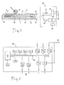
- FIG. 2 is a more detailed diagram of the principle of what an electronic system 10 can be, as presented in FIG. 1 and very complete, for any use according to the invention.
- microprocessor 12 which can be for example CPU type, operating at 4 MHz and 8 bits, and which can be controlled by a supervisor 17, associated with a clock.
- This microprocessor is connected by a central bus 20, making it possible then to add, if necessary, various other expansion cards, to specific cards, each corresponding to a function of the system: first of all, there are memory cards 13, of which the at least one can receive the program according to the method of the invention and another at least the data for comparing the derivatives of the impedances associated with the corresponding and reference impacts.
- the bus 20 is also connected to a decoding card 21, possibly necessary for certain input and output information, and to a baud generator 18.
- the constant current generator 11 can be a digital analog converter, controlled by the microprocessor and providing the sensor 6, on one of its output channels, with a constant current supply equal for example to 20 mA.
- a digital analog converter 141 collects the voltage variation at the edge of the sensor 6 and transmits it to the microprocessor 12, for calculation of the derivative and comparison then possible action through various output interfaces 15, to external actuators 16. These output interfaces can generate strong currents to act on relays and themselves understand a buffer memory capacity.
- Other input cards 14 can be managed by the same system and receive information from other external sensors, in particular, one of said cards 144 can be connected to a simple sensor acting in all or nothing like a counter, which sensor can be produced according to the description of the invention above, which can then be used directly if this is sufficient for the impedance and no longer its speed or derivative.
- This configuration of electronic system 10 can thus be suitable and be associated with any type of detection and action, including in particular those according to the method of the invention, which method can be operated with a single electronic system 10, connected to several sensors. and devices according to the preceding description.
Abstract
Description
La présente invention a pour objet des procédés et des dispositifs de détection et de reconnaissance d'impact par mesure de variation d'impédance.The present invention relates to methods and devices for detecting and recognizing impact by measuring variation in impedance.
Le secteur technique de l'invention est la fabrication de capteurs associés à un appareil de mesure et de calcul, permettant la détection, et surtout la reconnaissance d'impacts sur toute surface équipée d'un capteur.The technical sector of the invention is the manufacture of sensors associated with a measurement and calculation device, allowing the detection, and above all the recognition of impacts on any surface equipped with a sensor.
Une des applications principales de l'invention concerne tout les domaines de la surveillance des locaux pour déclencher tout type d'alerte, dès la détection d'une intrusion prédéterminée dans ces locaux, et ceux de la mécanique des fluides, et de la réalisation de peaux artificielles.One of the main applications of the invention relates to all the fields of surveillance of premises to trigger any type of alert, upon detection of a predetermined intrusion into these premises, and those of fluid mechanics, and the realization of artificial skins.
Une autre application est son utilisation dans le domaine sportif, chaque fois que l'on veut détecter par exemple la frappe d'une balle sur ou en dehors d'une ligne déterminée comme au tennis, sans être perturbé par d'autre type d'impact, comme ceux provoqués par les pieds des joueurs.Another application is its use in the sports field, each time that one wishes to detect for example the striking of a ball on or outside a determined line like in tennis, without being disturbed by other type of impact, like those caused by players' feet.
On connaît en effet divers procédés et dispositifs de détection utilisant diverses techniques : certains sont actifs; ils émettent des ondes, soit lumineuses, soit acoustiques, soit électromagnétiques et, par réflexion de celles-ci, ils détectent toute masse ou objet identifié ou non, qui se déplace ou se place dans l'espace qu'ils contrôlent.There are in fact known various detection methods and devices using various techniques: some are active; they emit waves, either light, acoustic or electromagnetic and, by reflection of these, they detect any mass or object identified or not, which moves or is placed in the space they control.
D'autres dispositifs sont plutôt passifs; ils n'émettent aucune onde ni signal en l'absence de perturbation et ne se déclenchent qu'en cas de changement dans l'état du paramètre qu'ils contrôlent (tel que la température, la pression, le contact, la luminosité, le bruit etc...).Other devices are rather passive; they do not emit any wave or signal in the absence of disturbance and are only triggered in the event of a change in the state of the parameter they control (such as temperature, pressure, contact, brightness, noise etc ...).
Chacun des procédés et dispositifs correspondant répond à une utilisation donnée, compte tenu des critères de détection souhaitée, et chacun a une fiabilité et une qualité propre. En particulier, quand on souhaite, comme pour la présente invention, détecter des impacts, on utilise essentiellement, soit de simples systèmes à contacts en tout ou rien qui ne déclenchent donc qu'à un seuil déterminé de déplacement dudit contact, soit des capteurs de mesure, qui permettent d'essayer de connaître au mieux la variation d'un paramètre physique tel que la pression, afin d'avoir une mesure quantitative de l'impact à partir de laquelle on peut déclencher diverses actions.Each of the corresponding methods and devices responds to a given use, taking into account the desired detection criteria, and each has its own reliability and quality. In particular, when it is desired, as for the present invention, to detect impacts, essentially, either simple systems with contacts in all or nothing which therefore only triggers a determined threshold of displacement of said contact, or measurement sensors, which allow to try to know as well as possible the variation of a physical parameter such as pressure, in order to have a quantitative measure of impact from which various actions can be triggered.
Dans ce domaine, on peut citer la demande de brevet de la Société "THE BENDIX CORPORATION", déposée le 15 Février 1978 aux ETATS-UNIS sous le NO. 878,056 et décrivant un "ensemble comportant un capteur capacitif et un circuit de démodulation", dont les revendications portent essentiellement sur ce circuit qui doit compenser les variations du signal de sortie produit par les erreurs de système : en effet, il est connu que toute mesure de capacité d'un circuit est fonction en particulier de la température et de l'hygrométrie du milieu. Il est donc nécessaire dans ce type de capteur et d'appareil, de corriger alors celle-ci, pour comparer des mesures de pression dans les même conditions.In this field, one can quote the patent application of the Company "THE BENDIX CORPORATION", filed on February 15, 1978 in the UNITED STATES under NO. 878.056 and describing a "set comprising a capacitive sensor and a demodulation circuit", the claims of which relate essentially to this circuit which must compensate for the variations in the output signal produced by system errors: indeed, it is known that any measurement the capacity of a circuit is a function in particular of the temperature and the hygrometry of the medium. In this type of sensor and device, it is therefore necessary to correct it, in order to compare pressure measurements under the same conditions.
Diverses autres demandes de brevets ont été déposées pour d'autres types de capteurs capacitifs, tel que la demande de la Société S.I.E. GmbH en ALLEMAGNE FEDERALE, sous le NO. G 87 06 280.1 du 1er Mai 1987, décrivant un capteur comportant trois électrodes flexibles et un circuit électronique délivrant un signal fonction de la déformation de ces électrodes due par exemple à la variation de la pression sur le capteur.Various other patent applications have been filed for other types of capacitive sensors, such as the application by the company S.I.E. GmbH in FEDERAL GERMANY, under NO. G 87 06 280.1 of May 1, 1987, describing a sensor comprising three flexible electrodes and an electronic circuit delivering a signal depending on the deformation of these electrodes due for example to the variation of the pressure on the sensor.
Pour obtenir des informations non seulement sur un point, mais sur une surface, divers capteurs ont été développés pour détecter des déformations de celles-ci toujours en utilisant des mesures électriques. La demande de brevet NO. 75/34.225 déposée le 05 Novembre 1975 par l'AGENCE NATIONALE DE VALORISATION POUR LA RECHERCHE - A.N.V.A.R., décrit un capteur tactile, dans le but de créer une "peau artificielle", comportant une multitude d'électrodes de mesure et d'éléments conducteurs, imbriqués les uns dans les autres et noyés dans un matériau dont la conductivité électrique dépend de sa compression.To obtain information not only on a point, but on a surface, various sensors have been developed to detect deformations of these always using electrical measurements. Patent application NO. 75 / 34.225 filed on 05 November 1975 by the NATIONAL DEVELOPMENT AGENCY FOR RESEARCH - ANVAR, describes a touch sensor, with the aim of creating an "artificial skin", comprising a multitude of measurement electrodes and conductive elements , nested one inside the other and embedded in a material whose electrical conductivity depends on its compression.
On pourrait citer d'autres demandes de brevets concernant divers autres dispositifs, dont l'objectif est de mesurer la pression subie par un support, sous l'effet par exemple d'une charge et à base de circuit capacitif.We could cite other patent applications concerning various other devices, the objective of which is to measure the pressure undergone by a support, under the effect for example of a load and based on a capacitive circuit.
La présente invention rentre dans cette catégorie de dispositifs et, plus spécialement à ceux destinés à des détections, sur des surfaces, d'impacts et à la reconnaissance de ces impacts pour déclencher des actions sélectives.The present invention falls into this category of devices and, more particularly to those intended for detections, on surfaces, of impacts and for the recognition of these impacts to trigger selective actions.
La plupart des systèmes cités précédemment sont effet basés :
- soit sur des mesures actives par émission d'ondes dont la réflexion est essentiellement monoqualitative et permet une détection en fait par tout ou rien, ou si l'on veut en plus soit une mesure multiqualitative, soit une mesure quantitative par ces procédés, cela nécessite des appareillages d'analyse de forme et de calcul très complexes et très coûteux;
- soit sur des mesures passives par calcul de la grandeur que l'on peut alors quantifier pour en interpréter l'origine et en déduire une analyse qualitative pour sélectionner les actions souhaitées, mais dont la fiabilité est douteuse et le réglage doit être permanent.Most of the systems mentioned above are effect based:
- either on active measurements by emission of waves whose reflection is essentially monoqualitative and allows detection in fact by all or nothing, or if we want in addition either a multiqualitative measurement, or a quantitative measurement by these processes, this requires very complex and very costly form analysis and calculation apparatus;
- Either on passive measurements by calculating the quantity that can then be quantified to interpret the origin and deduce a qualitative analysis to select the actions desired, but whose reliability is doubtful and the adjustment must be permanent.
Aucun de ces systèmes ne permet donc une utilisation à la fois pour la détection d'impacts, quelles que soient la situation et les conditions d'environnement, et surtout pour la reconnaissance de ces impacts sans un appareillage complexe ou un réglage permanent.None of these systems therefore allows use both for the detection of impacts, whatever the situation and the environmental conditions, and above all for the recognition of these impacts without complex apparatus or permanent adjustment.
Un des problèmes posés est en effet de pouvoir détecter et sélectionner en particulier sur une surface donnée, au moins un type d'impact que l'on s'est préalablement défini et seulement celui-ci, et cela dans toute circonstance et quel que soit l'état de ladite surface au moment de l'impact.One of the problems posed is in fact to be able to detect and select in particular on a given surface, at least one type of impact that has been defined beforehand and only this, and this in any circumstance and whatever the state of said surface at the time of impact.
Une solution au problème posée est un procédé de détection et de reconnaissance d'impact reçu par une surface, comportant les opérations suivantes :
- on dispose au moins deux couches de matériaux, conducteurs d'électricité en contact l'une de l'autre, pour constituer un capteur, dont on recouvre ladite surface ;
- on relie chacune des couches externes à une borne d'un système électronique comportant au moins un générateur de courant, constant parcourant alors lesdites couches, un microprocesseur associé au moins à une mémoire et permettant en particulier la mesure de la différence de potentiel aux bornes dudit capteur, et diverses interfaces d'entrées-sorties ;
- on calcule la vitesse de variation de l'impédance de ce capteur qui change quand il est soumis à un phénomène physique différent de celui de sa situation initiale, laquelle vitesse de variation d'impédance est directement proportionnelle à la dérivée de la différence de potentiel mesurée;
- dans une première phase d'apprentissage, on enregistre dans ladite mémoire du système électronique, la valeur de l'impédance du capteur dit alors au repos et correspondant à une situation initiale donnée, et à chaque variation de cette impédance dans la phase d'utilisation, ledit microprocesseur ayant été préalablement programmé pour cela, adresse un signal donné à travers une interface de sortie, dès que la vitesse de ladite variation dépasse un seuil déterminé.A solution to the problem posed is a method for detecting and recognizing the impact received by a surface, comprising the following operations:
- There are at least two layers of materials, electrical conductors in contact with each other, to form a sensor, which covers said surface;
- each of the external layers is connected to a terminal of an electronic system comprising at least one constant current generator then traversing said layers, a microprocessor associated at least with a memory and allowing in particular the measurement of the potential difference at the terminals said sensor, and various input-output interfaces;
- the speed of variation of the impedance of this is calculated sensor which changes when it is subjected to a physical phenomenon different from that of its initial situation, which speed of variation of impedance is directly proportional to the derivative of the measured potential difference;
in a first learning phase, the value of the sensor impedance is said to be at rest and corresponding to a given initial situation, and in each variation of this impedance in the phase of use, said microprocessor having been previously programmed for this, sends a given signal through an output interface, as soon as the speed of said variation exceeds a determined threshold.
Une autre solution au problème posé est un dispositif de détection et de reconnaissance d'impact reçu par une surface de type comportant un capteur de pression par mesure de l'impédance dudit capteur associé à un système électronique permettant ladite mesure, dans lequel ledit capteur est constitué au moins de deux couches de matériaux conducteurs d'électricité, en contact et disposées par exemple parallèles l'une sur l'autre, recouvrant ladite surface, et dont les couches externes sont reliées chacune depuis au moins un point quelconque de leurs surfaces à une borne dudit système électronique. Ce système électronique comporte au moins un générateur de courant constant parcourant alors lesdites couches, un microprocesseur associé à au moins une mémoire et permettant en particulier la mesure de la différence de potentiel au bord dudit capteur, le calcul de la dérivée de cette différence de potentiel, la comparaison du résultat obtenu à des valeurs de dérivées stockées dans ladite mémoire et associés à un type d'impact déterminé préalablement, et l'émission de signal à travers au moins une interface de sortie, quand ladite comparaison correspond à un choix de détection et de reconnaissance voulu.Another solution to the problem posed is an impact detection and recognition device received by a surface of the type comprising a pressure sensor by measuring the impedance of said sensor associated with an electronic system allowing said measurement, in which said sensor is consisting of at least two layers of electrically conductive materials, in contact and arranged for example parallel to each other, covering said surface, and the external layers of which are each connected from at least any point on their surfaces to a terminal of said electronic system. This electronic system comprises at least one constant current generator then traversing said layers, a microprocessor associated with at least one memory and allowing in particular the measurement of the potential difference at the edge of said sensor, the calculation of the derivative of this potential difference , the comparison of the result obtained with derivative values stored in said memory and associated with a type of impact determined previously, and the emission of signal through at least one output interface, when said comparison corresponds to a choice of detection and wanted recognition.
Dans un mode de réalisation préférentiel un procédé de détection et de reconnaissance d'impact suivant la présente invention, comporte les opérations suivantes :
- lors de ladite première phase d'apprentissage, on associe et on stocke dans ladite mémoire du système chaque dite vitesse de variation et la nature du phénomène alors connu qui a provoqué cette variation et qui lui est spécifique pour ladite surface;
- on établit une classification et une sélection parmi tous les phénomènes qui peuvent provoquer une variation de l'impédance, et on programme ledit microprocesseur pour que dans la phase d'utilisation, il adresse un signal donné vers une interface de sortie pour seulement certaines vitesses de variation de cet impédance.In a preferred embodiment, an impact detection and recognition method according to the present invention comprises the following operations:
- during said first learning phase, each said speed of variation and the nature of the phenomenon then known which caused this variation and which is specific to it for said surface are associated and stored in said system memory;
- we establish a classification and a selection among all the phenomena which can cause a variation of the impedance, and we program said microprocessor so that in the use phase, it sends a given signal to an output interface for only certain speeds variation in this impedance.
Le résultat est de nouveaux procédés et dispositifs de détection d'impacts par mesures de vitesse de variation d'impédance, dont les caractéristiques permettent de satisfaire diverses applications, quelles que soient les conditions d'environnement de celle-ci.The result is new methods and devices for detecting impacts by measuring impedance variation speed, the characteristics of which make it possible to satisfy various applications, whatever the environmental conditions thereof.
En effet, la présente invention a pour principal avantage de permettre une mesure qualitative du phénomène et non quantitative. En effet, actuellement, il n'existe pas de capteur pouvant réagir aux impacts et de les discriminer.The main advantage of the present invention is that it allows a qualitative measurement of the phenomenon and not a quantitative one. Indeed, currently, there is no sensor that can react to impacts and discriminate them.
Le dispositif suivant l'invention décrit ci-après n'est pas un capteur de mesure au sens propre du terme.The device according to the invention described below is not a measurement sensor in the proper sense of the term.
Ainsi, la présente invention peut avoir de multiples applications en tant qu'interrupteur, contact et détection dans les domaines tels que la surveillance, la sécurité, la gestion de stock, le sport, la mécanique des fluides, la robotique (peau artificielle), l'acoustique etc....Thus, the present invention can have multiple applications as a switch, contact and detection in fields such as surveillance, security, stock management, sports, fluid mechanics, robotics (artificial skin), acoustics etc ...
Compte tenu des faibles courants considérés pour son fonctionnement, les capteurs suivant l'invention peuvent fonctionner dans n'importe quelle atmosphère et même dans l'eau, car ils ne présentent aucun risque d'électrocution.Given the low currents considered for its operation, the sensors according to the invention can operate in any atmosphere and even in water, since they do not present any risk of electrocution.
De plus, la forme du capteur importe peu pour le fonctionnement du procédé : on peut même envisager que l'adaptation de forme pourra être faite par l'utilisateur final qui adapte ledit capteur sur la surface qu'il détermine, tant en dimension qu'en mise en forme sur celle-ci, puisque dans la présente invention, l'état initial qui détermine la valeur de l'impédance du capteur dit au repos, n'intervient pas dans l'analyse de la variation de celle-ci.In addition, the shape of the sensor does not matter for the operation of the process: it can even be envisaged that the shape adaptation may be made by the end user who adapts said sensor to the surface that he determines, both in size and in formatting thereon, since in the present invention, the initial state which determines the value of the impedance of the said sensor at rest, does not intervene in the analysis of the variation thereof.
On peut installer le dispositif sur tout support et surface.The device can be installed on any support and surface.
On a pu constater, mesurer et enregistrer, qu'une fois la mise en place sur une surface donnée, la dérivée de l'impédance du capteur est toujours la même pour un impact donné, quelles que soient la valeur initiale de cette impédance avant l'impact, et les autres conditions d'environnement qui peuvent ainsi changer dans le temps comme en particulier, la température, l'hygrométrie ou même avec toute charge posée sur la surface et donnant une déformation quasi permanente audit capteur.We could see, measure and record that once the installation on a given surface, the derivative of the sensor impedance is always the same for a given impact, whatever the initial value of this impedance before l impact, and other environmental conditions that may change over time as in particular, the temperature, the humidity or even with any load placed on the surface and giving an almost permanent deformation to said sensor.
L'information recueillie est alors l'image non quantifiée du phénomène, mais dont les caractéristiques qualitatives déterminées par une ou plusieurs valeurs de dérivées, associée ou non à une durée et à une ou des accélérations, permettent de classer ledit phénomène d'une manière certaine et donc de le reconnaître, de le sélectionner au milieu d'autres et de déclencher toute action souhaitée suivant l'usage retenu.The information collected is then the unquantified image of the phenomenon, but whose qualitative characteristics determined by one or more values of derivatives, associated or not with a duration and with one or more accelerations, make it possible to classify said phenomenon in a way certain and therefore to recognize it, to select it in the middle of others and to trigger any desired action according to the chosen use.
Dans le dispositif suivant, nous décrirons essentiellement un exemple de procédé et de dispositif suivant l'invention, mais d'autres réalisations peuvent être envisagées et les figures, dessins et descriptifs ci-après n'ont aucun caractère limitatif.
- La figure 1 est une vue d'un exemple de dispositif suivant l'invention, comportant un capteur en coupe et un schéma d'un système électronique associé.
- La figure 2 est un schéma plus détaillé de principe dudit système électronique.
- FIG. 1 is a view of an example of a device according to the invention, comprising a sectional sensor and a diagram of an associated electronic system.
- Figure 2 is a more detailed block diagram of said electronic system.
La figure 1 représente une vue en coupe d'un capteur 6 suivant l'invention, posé sur une surface 8 quelconque et relié à un système électronique 10, dont un exemple de schéma plus détaillé est décrit dans la figure 2.FIG. 1 represents a sectional view of a
Le capteur 6 est constitué essentiellement d'au moins deux couches 1 et 2 de matériaux conducteurs de tout type, compressibles ou non, souples ou non, et en contact les unes des autres. Les couches de matériaux sont disposées de préférence, parallèles l'une sur l'autre et recouvrent la surface 8 sur laquelle le capteur doit détecter les impacts et les reconnaître. Ainsi, de préférence, lesdites couches sont souples pour épouser la forme de ladite surface et leur dimension extérieure peut être quelconque.The
Dans un mode de réalisation préférentiel, ces couches sont séparées par une couche 5 de matériau. Quand les couches 1 et 2 sont constituées de matériaux non compressibles, celui de la couche intermédiaire 5 peut être :
- soit conducteur, souple, compressible, déformable et élastique permettant alors de différencier plus facilement des objets 9, qui viennent frapper la face supérieure du capteur 6, en un point d'impact 19, et comprimer ainsi plus ou moins en valeur et en vitesse cette couche intermédiaire 5, créant ainsi une variation d'impédance plus facile à détecter et à mesurer;
- soit isolant, souple et ajouré et pouvant permettre alors une discrimination géographique de l'endroit où se trouve le point d'impact 19 sur la surface du capteur.In a preferred embodiment, these layers are separated by a
- either conductive, flexible, compressible, deformable and elastic, making it easier to differentiate objects 9, which strike the upper face of the
- Is insulating, flexible and perforated and can then allow geographic discrimination of the location of the point of
Quand les couches 1 et 2 sont constituées de matériau compressible, déformable et élastique (mousse conductrice par exemple), ce matériau de la couche intermédiaire 5 peut être comme ci-dessus, et même non compressible, car la compression affecte alors de toute façon les couches extérieures.When the
Dans un autre mode de réalisation, on peut constituer un capteur en remplissant un fourreau de toute forme de plusieurs morceaux distincts de matériau conducteur, type morceau de mousse, constituant autant de couches externes et intermédiaiaires, dont on relie les extrémités au système électronique 10.In another embodiment, a sensor can be formed by filling a sheath of any shape with several distinct pieces of conductive material, such as a piece of foam, constituting as many external and intermediate layers, the ends of which are connected to the
De plus, les couches conductrices 1 et 2 sont reliées chacune depuis au moins un point quelconque 7₁ et 7₂ respectivement de leur surface, par des contacts de tout type connu tel que rivets, bornes à visser, soudure etc..., à des conducteurs 4, connectés eux-mêmes à un système électronique 10.In addition, the
Dans un mode de réalisation préférentiel, cesdits points 7₁ et 7₂ sont éloignés le plus possible l'un par rapport à l'autre, car plus ils sont éloignés les uns des autres, plus la sensibilité du dispositif est grande.In a preferred embodiment, said
Dans une variante de l'invention, ces couches conductrices 1 et 2 constituent elles-mêmes l'enveloppe du capteur 6, et dans une autre variante, ces couches sont enfermées et recouvertes dans une enveloppe protectrice souple 3, dont les extrémités et les bords sont refermés par n'importe quel moyen, lesdites couches pouvant être solidaires ou non de cette enveloppe.In a variant of the invention, these
L'épaisseur de cesdites couches et enveloppes peut être quelconque, mais de préférence assez mince, pour constituer un capteur assez plat et donc discret.The thickness of these layers and envelopes can be any, but preferably thin enough, to constitute a fairly flat and therefore discreet sensor.
Ledit système électronique 10 comporte au moins un générateur 11 de courant constant, afin de ne pas être influencé par la longueur des conducteurs 4 et qui, par exemple produit un courant très faible de l'ordre de20 mA et même moins.Said
En parallèle et suivant par exemple le schéma de la figure 2, ledit système 10 comprend aussi un convertisseur analogique digital 14 qui transmet à un microprocesseur 12 la valeur de la différence de potentiel U mesurée aux bornes du capteur sur les fils d'alimentation 4 suivant la formule U = ZI, dans laquelle l'intensité I est donc constante et Z représente l'impédance du circuit électrique constitué par le capteur 10 : à un instant donné considéré alors au repos, l'impédance et l'intensité étant constantes, la dérivée δU de la tension est nulle et quand un objet 9 frappe le capteur 10, la déformation des couches conductrices 1 et 2, et éventuellement de la couche intermédiaire 5, provoque une variation de l'impédance du circuit, dont la dérivée est alors directement proportionnelle à celle de la tension mesurée :
δU = f(z) dt car δI = 0
où f(z) = dérivée de l'impédance.In parallel and following for example the diagram of FIG. 2, said
δU = f (z) dt because δI = 0
where f (z) = derived from impedance.
On a pu expérimenter et vérifier que pour un capteur suivant l'invention, adapté à une surface donnée, et pour un impact déterminé, cette dérivée était constante, quelle que soit la valeur Z₀ de l'impédance initiale du capteur avant l'impact et permet donc de reconnaître divers types d'impacts et de sélectionner ceux pour lesquels on veut pouvoir agir sur des éléments externes 16, à travers une interface 15, en ignorant ceux qui n'intéressent pas l'utilisateur. Ainsi, dans une utilisation sur un terrain de tennis, dans lequel les bandes qui délimitent celui-ci seraient muni d'un dispositif suivant l'invention, ce dispositif ne pourrait agir seulement lorsqu'une balle touche lesdites bandes et ne pas réagir quand c'est le joueur qui marche dessus.We were able to experiment and verify that for a sensor according to the invention, adapted to a given surface, and for a determined impact, this derivative was constant, whatever the value Z₀ of the initial impedance of the sensor before impact and therefore makes it possible to recognize various types of impact and to select those for which it is desired to be able to act on
Pour cela, il est nécessaire alors d'effectuer pour chaque utilisation et surface donnée une phase d'apprentissage, durant laquelle on enregistre dans une mémoire 13 associée au microprocesseur 12, les vitesses ou les dérivées de variation de ladite impédance correspondant aux impacts que l'on veut sélectionner ou au contraire éliminer.For this, it is then necessary to carry out, for each use and given surface, a learning phase, during which the speeds or the derivatives of variation of said impedance corresponding to the impacts that l are recorded in a
Le rôle du microprocesseur est de calculer à tout moment cette dérivée, et ladite mémoire 13, ou une autre, contient également tout le programme d'application qui, dans la phase d'utilisation, exploite le résultat du calcul et le compare à un ou plusieurs seuils figés ou paramétrés pendant la phase d'apprentissage, afin de déclencher ou non l'action souhaitée.The role of the microprocessor is to calculate this derivative at any time, and said
Lors de la première mise sous tension, le programme initialise le système et il est possible également après toute détection de variation de l'impédance du capteur, quand celle-ci prend ensuite toujours les mêmes valeurs de dérivées pendant une durée minimum déterminée, de programmer le microprocesseur 12 pour qu'il prenne comme nouvelle valeur de l'impédance du capteur au repos, celle correspondant à sa valeur de dérivée nulle, et qu'il ne détecte ensuite que les variations d'impédance créées par un nouvel impact qui produit une dérivée différente desdites valeurs ci-dessus.During the first power-up, the program initializes the system and it is also possible after any detection of a variation in the sensor impedance, when it then always takes the same derivative values for a determined minimum duration, to program the
De plus ladite valeur de l'impédance de référence du capteur considéré au repos à un instant donné peut être réactulisé à des intervalles de temps donné tel que quelques microsecondes, correspondant à un cycle de programme dudit microprocesseur 12 et adapté à une application donnée.Furthermore, said value of the reference impedance of the sensor considered to be at rest at a given instant can be reactivated at given time intervals such as a few microseconds, corresponding to a program cycle of said
De toute façon, comme nous l'avons déjà expliqué, le procédé suivant l'invention utilise le calcul de la dérivée de la valeur d'impédance et non sa valeur absolue : ainsi toute variation lente telle que due à la température ou à l'hygrométrie, induit une dérivée très faible, qui sera en-dessous de tout seuil correspondant à un impact, et ne déclenchera pas, si on le désire, d'action.Anyway, as we have already explained, the method according to the invention uses the calculation of the derivative of the impedance value and not its absolute value: thus any slow variation such as due to the temperature or to the hygrometry, induces a very weak derivative, which will be below any threshold corresponding to an impact, and will not trigger, if desired, action.
Si l'on souhaite une plus grand discrimination dans l'analyse des impacts, on peut enregistrer, avec chaque valeur de la vitesse de variation de l'impédance, la durée pendant laquelle cette vitesse peut rester constante, ainsi que les dérivées de la vitesse entre l'état dit au repos du capteur et son retour à cet état.If we want greater discrimination in the impact analysis, we can record, with each value of the speed of variation of the impedance, the duration during which this speed can remain constant, as well as the derivatives of the speed. between the state said at rest of the sensor and its return to this state.
La figure 2 est un schéma plus détaillé de principe de ce que peut être un système électronique 10, tel que présenté dans la figure 1 et très complet, pour toute utilisation suivant l'invention.FIG. 2 is a more detailed diagram of the principle of what an
Il comprend divers composants électroniques connus et seuls la combinaison et le procédé d'utilisation de ceux-ci avec un programme spécifique tel que décrit précédemment, fait l'objet de la présente invention.It comprises various known electronic components and only the combination and the method of using these with a specific program as described above, is the subject of the present invention.
On retrouve donc le microprocesseur 12 qui peut être par exemple de type CPU, fonctionnant à 4MHz et 8 bits, et qui peut être contrôlé par un superviseur 17, associé à une horloge. Ce microprocesseur est relié par un bus central 20, permettant de rajouter ensuite si nécessaire diverses autres cartes d'extension, à des cartes spécifiques, correspondant chacune à une fonction du système : on trouve tout d'abord, des cartes mémoires 13, dont l'une au moins peut recevoir le programme suivant le procédé de l'invention et une autre au moins les données de comparaison des dérivées des impédances associées aux impacts correspondants et de référence.We thus find the
Le bus 20 est aussi relié à une carte de décodage 21, éventuellement nécessaire pour certaines informations d'entrée et de sortie, et à un générateur de bauds 18.The
Le générateur 11 de courant constant peut être un convertisseur digital analogique, contrôlé par le microprocesseur et assurant au capteur 6, sur une de ses voies de sortie, une alimentation de courant constant égal par exemple à 20 mA.The constant
En retour et en parallèle, un convertisseur analogique digital 14₁ recueille la variation de tension au bord du capteur 6 et la transmet au microprocesseur 12, pour calcul de la dérivée et comparaison puis action éventuelle à travers diverses interfaces de sortie 15, vers des actionneurs externes 16. Ces interfaces de sortie peuvent générer des courants forts pour agir sur des relais et comprendre elles-mêmes une capacité mémoire tampon.In return and in parallel, a digital analog converter 14₁ collects the voltage variation at the edge of the
D'autres cartes d'entrée 14 peuvent être gérées par le même système et recevoir des informations d'autres capteurs externes, en particulier, une desdites cartes 14₄ peut être connectée à un simple capteur agissant en tout ou rien à la manière d'un compteur, lequel capteur peut être réalisé suivant le descriptif de l'invention ci-dessus, dont on peut utiliser alors directement si cela suffit l'impédance et non plus sa vitesse ou dérivée.
Cette configuration de système électronique 10 peut ainsi convenir et être associée à tout type de détection et d'action, dont en particulier celles suivant le procédé de l'invention, lequel procédé peut être exploité avec un seul système électronique 10, connecté à plusieurs capteurs et dispositifs suivant le descriptif précédent.This configuration of
Il est à noter que les procédés et dispositifs suivant l'invention décrite permettent la détection et la reconnaissance non seulement d'impacts, mais également de retraits, phénomènes symétriques et mesurables de la même façon comme par exemple quand on retire un objet d'une surface.It should be noted that the following methods and devices the invention described allows the detection and recognition not only of impacts, but also of withdrawals, symmetrical phenomena which can be measured in the same way as for example when an object is removed from a surface.
Claims (11)
- on dispose au moins deux couches de matériaux (1 et 2), conductrices d'électricité et en contact l'une de l'autre, pour constituer un capteur (6), dont on recouvre ladite surface (8);
- on relie chacune des couches externes à une borne d'un système électronique (10) comportant au moins un générateur (11) de courant constant parcourant alors lesdites couches, un microprocesseur (12) associé au moins à une mémoire (13) et permettant en particulier la mesure de la différence de potentiel aux bornes dudit capteur, et diverses interfaces d'entrées-sorties (15);
- on calcule la vitesse de variation de l'impédance de ce capteur qui change quand il est soumis à un phénomène physique différent de celui de sa situation initiale, laquelle vitesse de variation d'impédance est directement proportionnelle à la dérivée de la différence de potentiel mesurée;
- dans une première phase d'apprentissage. on enregistre dans ladite mémoire du système électronique (10), la valeur de l'impédance du capteur dit alors au repos et correspondant à une situation initiale donnée, et à chaque variation de cette impédance dans la phase d'utilisation, ledit microprocesseur ayant été programmé préalablement pour cela, adresse un signal donné à travers une interface de sortie (15), dès que la vitesse de ladite variation dépasse un seuil déterminé.1. Method for detecting and recognizing impact received by a surface, characterized in that:
- There are at least two layers of materials (1 and 2), electrically conductive and in contact with each other, to form a sensor (6), which covers said surface (8);
- Each of the external layers is connected to a terminal of an electronic system (10) comprising at least one generator (11) of constant current then traversing said layers, a microprocessor (12) associated at least with a memory (13) and allowing in particular the measurement of the potential difference across said sensor, and various input-output interfaces (15);
- we calculate the speed of variation of the impedance of this sensor which changes when it is subjected to a physical phenomenon different from that of its initial situation, which speed of variation of impedance is directly proportional to the derivative of the potential difference measured;
- in a first learning phase. is recorded in said memory of the electronic system (10), the value of the sensor impedance then said to be at rest and corresponding to a given initial situation, and to each variation of this impedance in the use phase, said microprocessor having been programmed beforehand for this purpose, sends a given signal through an output interface (15), as soon as the speed of said variation exceeds a determined threshold.
- lors de ladite première phase d'apprentissage, on associe et on stocke dans ladite mémoire (13) du système chaque dite vitesse de variation et la nature du phénomène alors connu qui a provoqué cette variation et qui lui est spécifique pour ladite surface;
- on établit une classification et une sélection parmi tous les phénomènes qui peuvent provoquer une variation de l'impédance. et on programme ledit microprocesseur (12) pour que dans la phase d'utilisation, il adresse un signal donné vers une interface de sortie (15) pour seulement certaines vitesses de variation de cet impédance.2. Method for detecting and recognizing impact according to claim 1, characterized in that:
- During said first learning phase, each said speed of variation and the nature of the phenomenon then known which caused this variation and which is specific to it for said surface are associated and stored in said system memory (13);
- a classification and a selection are made among all the phenomena which can cause a variation in the impedance. and said microprocessor (12) is programmed so that in the use phase, it sends a given signal to an output interface (15) for only certain speeds of variation of this impedance.
Applications Claiming Priority (2)
| Application Number | Priority Date | Filing Date | Title |
|---|---|---|---|
| FR8807319 | 1988-05-30 | ||
| FR8807319A FR2632069B1 (en) | 1988-05-30 | 1988-05-30 | IMPEDANCE VARIATION SPEED DETECTION SENSOR OR IMPEDANCE VARIATION SPEED |
Publications (1)
| Publication Number | Publication Date |
|---|---|
| EP0345181A1 true EP0345181A1 (en) | 1989-12-06 |
Family
ID=9366845
Family Applications (1)
| Application Number | Title | Priority Date | Filing Date |
|---|---|---|---|
| EP89430012A Withdrawn EP0345181A1 (en) | 1988-05-30 | 1989-05-19 | Process and appliance for detecting and recognizing impact by measuring the impedance variation |
Country Status (5)
| Country | Link |
|---|---|
| US (1) | US4990897A (en) |
| EP (1) | EP0345181A1 (en) |
| JP (1) | JPH02118455A (en) |
| AU (1) | AU3513289A (en) |
| FR (1) | FR2632069B1 (en) |
Cited By (1)
| Publication number | Priority date | Publication date | Assignee | Title |
|---|---|---|---|---|
| EP0559634A1 (en) * | 1992-03-02 | 1993-09-08 | Hoerbiger Ventilwerke Aktiengesellschaft | Position sensor |
Families Citing this family (8)
| Publication number | Priority date | Publication date | Assignee | Title |
|---|---|---|---|---|
| US5471192A (en) * | 1994-01-24 | 1995-11-28 | Dash; Glen | Sound producing device stimulated by petting |
| US6598485B1 (en) * | 2000-11-24 | 2003-07-29 | Sinotech Engineering Consultants, Inc. | Method and device for evaluating quality of concrete structures |
| US20060287140A1 (en) * | 2005-06-16 | 2006-12-21 | Brandt Richard A | Automated line calling system |
| FI20075775A0 (en) * | 2007-10-31 | 2007-10-31 | A4Sp Technologies Ltd | Sports performance system |
| US7772960B2 (en) | 2007-11-27 | 2010-08-10 | Interlink Electronics, Inc. | Pre-loaded force sensing resistor and method |
| DE102011078746A1 (en) * | 2011-07-06 | 2013-01-10 | Robert Bosch Gmbh | Device for detecting object i.e. airplane, during docking of object at gate of airport, has measuring device for detecting distance pattern and detecting object in area when portion of distance pattern remains constant temporally |
| US10500471B2 (en) * | 2013-05-17 | 2019-12-10 | CNOWire, Inc. | Impedance-based impact determination and scoring |
| CN114111549A (en) * | 2021-11-30 | 2022-03-01 | 北京清航紫荆装备科技有限公司 | Membrane spacecraft and impact damage detection circuit and method thereof |
Citations (5)
| Publication number | Priority date | Publication date | Assignee | Title |
|---|---|---|---|---|
| DE2529475A1 (en) * | 1975-07-02 | 1977-01-13 | Klaus Dr Nicol | DEVICE FOR THE TIME-DEPENDENT MEASUREMENT OF PHYSICAL SIZES |
| FR2344006A1 (en) * | 1976-03-12 | 1977-10-07 | Kavlico Corp | CAPACITIVE PRESSURE TRANSDUCER AND METHOD FOR MANUFACTURING SUCH A TRANSDUCER |
| GB2013434A (en) * | 1978-01-30 | 1979-08-08 | Exxon Research Engineering Co | Method and apparatus for compensating a sensor |
| FR2417887A1 (en) * | 1978-02-15 | 1979-09-14 | Bendix Corp | SET CONTAINING A CAPACITIVE SENSOR AND A DEMODULATION CIRCUIT |
| DE8706280U1 (en) * | 1987-05-01 | 1987-06-19 | Sie Sensorik Industrie-Elektronik Gmbh, 6806 Viernheim, De |
Family Cites Families (3)
| Publication number | Priority date | Publication date | Assignee | Title |
|---|---|---|---|---|
| US4062008A (en) * | 1976-02-09 | 1977-12-06 | Nils Jeppson | System for selective detection and indication of impacts upon a base surface |
| US4289035A (en) * | 1978-02-15 | 1981-09-15 | The Bendix Corporation | Compensated capacitive transducer demodulator circuit |
| US4855711A (en) * | 1987-06-29 | 1989-08-08 | Sensor Science | Impact detection apparatus |
-
1988
- 1988-05-30 FR FR8807319A patent/FR2632069B1/en not_active Expired - Lifetime
-
1989
- 1989-05-19 EP EP89430012A patent/EP0345181A1/en not_active Withdrawn
- 1989-05-24 US US07/356,796 patent/US4990897A/en not_active Expired - Fee Related
- 1989-05-24 AU AU35132/89A patent/AU3513289A/en not_active Abandoned
- 1989-05-30 JP JP1137334A patent/JPH02118455A/en active Pending
Patent Citations (5)
| Publication number | Priority date | Publication date | Assignee | Title |
|---|---|---|---|---|
| DE2529475A1 (en) * | 1975-07-02 | 1977-01-13 | Klaus Dr Nicol | DEVICE FOR THE TIME-DEPENDENT MEASUREMENT OF PHYSICAL SIZES |
| FR2344006A1 (en) * | 1976-03-12 | 1977-10-07 | Kavlico Corp | CAPACITIVE PRESSURE TRANSDUCER AND METHOD FOR MANUFACTURING SUCH A TRANSDUCER |
| GB2013434A (en) * | 1978-01-30 | 1979-08-08 | Exxon Research Engineering Co | Method and apparatus for compensating a sensor |
| FR2417887A1 (en) * | 1978-02-15 | 1979-09-14 | Bendix Corp | SET CONTAINING A CAPACITIVE SENSOR AND A DEMODULATION CIRCUIT |
| DE8706280U1 (en) * | 1987-05-01 | 1987-06-19 | Sie Sensorik Industrie-Elektronik Gmbh, 6806 Viernheim, De |
Non-Patent Citations (2)
| Title |
|---|
| ELECTRONIC ENGINEERING, vol. 45, no. 540, février 1973, page 27; D.W. RUSSELL: "Detecting capacitance changes in transducers" * |
| JOURNAL OF THE AUDIO ENGINEERING SOCIETY, vol. 33, no. 6, juin 1985, pages 430-435, New York, US; J.A.M. CATRYSSE: "On the design of some feedback circuits for loudspeakers" * |
Cited By (1)
| Publication number | Priority date | Publication date | Assignee | Title |
|---|---|---|---|---|
| EP0559634A1 (en) * | 1992-03-02 | 1993-09-08 | Hoerbiger Ventilwerke Aktiengesellschaft | Position sensor |
Also Published As
| Publication number | Publication date |
|---|---|
| AU3513289A (en) | 1989-11-30 |
| US4990897A (en) | 1991-02-05 |
| FR2632069B1 (en) | 1990-12-14 |
| FR2632069A1 (en) | 1989-12-01 |
| JPH02118455A (en) | 1990-05-02 |
Similar Documents
| Publication | Publication Date | Title |
|---|---|---|
| EP1941475B1 (en) | Method for processing acceleration measurements, acceleration sensor and alarm system equipped with such sensors | |
| FR2511796A1 (en) | CONTACT DETECTION DISPLAY DEVICE AND METHOD FOR LOCATING CAPACITIVE CONTACT | |
| EP2431911B1 (en) | Device for protecting a connector and a communication wire of a memory-card reader. | |
| EP0345181A1 (en) | Process and appliance for detecting and recognizing impact by measuring the impedance variation | |
| FR2785046A1 (en) | Measuring permittivity between probes by charging measuring probe from direct current supply of controlled amplitude and then connecting it to integrating and processing stages | |
| CA2466675C (en) | .wire security device for detecting theft of a protected object and operating method | |
| FR2755526A1 (en) | SYSTEM FOR READING DIGITAL IMPRESSIONS WITH INTEGRATED HEATING RESISTORS | |
| EP2030143B1 (en) | Device to shield against interference from electrical appliances | |
| WO2010037988A1 (en) | Method and device for the non-intrusive determination of the electrical power consumed by an installation, by analysing load transients | |
| FR2964772A1 (en) | DEVICE FOR PROTECTING AN ELECTRONIC PRINTED CIRCUIT. | |
| EP3264116A1 (en) | Device for detecting an electric arc from the acoustic signature thereof | |
| EP3086910A1 (en) | Impact detection system for robotic device | |
| EP0231549A1 (en) | Protected enclosure with electrical switch and its application | |
| EP2548236A2 (en) | Mechanical stress detector | |
| EP3723003A1 (en) | A smartcard including a fingerprint sensor | |
| EP3353704A1 (en) | Device for protecting an electronic circuit with detection of a change of electrical reactance | |
| FR2661753A1 (en) | METHOD FOR IMPROVING THE PRECISION OF IMPEDANCE SENSORS IN RADIOSONDES. | |
| WO2019102130A1 (en) | Control device for a power tool and safety tool comprising such a control device | |
| EP0772851B1 (en) | Fire detector comprising an analog sensor | |
| EP3893727B1 (en) | Device for measuring the therapeutic observance of the wearing of a textile item by a patient, instrumented item comprising such a device, and measurement method | |
| US20220412836A1 (en) | Low power memristive vacuum sensor | |
| FR2485774A1 (en) | Magnetic reed switch position detector e.g. for safe door - has test coil which acts against contact element to provide periodic testing of response of switch | |
| FR2876480A1 (en) | Intrusion detection system for building, has cable disposed on part of circumference of leaf or frame and forming transducer for transforming force exerted on cable into measurable electrical magnitude | |
| FR2782159A1 (en) | Device for detection of an attempt to break into a secure container has a system of wire type sensors connected to analysis electronics for determination of variations in resistance and hence break in attempts | |
| WO2023242519A1 (en) | Polymeric deformation sensor |
Legal Events
| Date | Code | Title | Description |
|---|---|---|---|
| PUAI | Public reference made under article 153(3) epc to a published international application that has entered the european phase |
Free format text: ORIGINAL CODE: 0009012 |
|
| AK | Designated contracting states |
Kind code of ref document: A1 Designated state(s): AT BE CH DE ES FR GB GR IT LI LU NL SE |
|
| 17P | Request for examination filed |
Effective date: 19900605 |
|
| 17Q | First examination report despatched |
Effective date: 19920717 |
|
| STAA | Information on the status of an ep patent application or granted ep patent |
Free format text: STATUS: THE APPLICATION IS DEEMED TO BE WITHDRAWN |
|
| 18D | Application deemed to be withdrawn |
Effective date: 19921203 |