EP0345034B1 - Fixiergerät für ein Tonerbild in einer Bilderzeugungsmaschine - Google Patents
Fixiergerät für ein Tonerbild in einer Bilderzeugungsmaschine Download PDFInfo
- Publication number
- EP0345034B1 EP0345034B1 EP89305467A EP89305467A EP0345034B1 EP 0345034 B1 EP0345034 B1 EP 0345034B1 EP 89305467 A EP89305467 A EP 89305467A EP 89305467 A EP89305467 A EP 89305467A EP 0345034 B1 EP0345034 B1 EP 0345034B1
- Authority
- EP
- European Patent Office
- Prior art keywords
- fixing
- toner image
- sheet medium
- image
- rollers
- Prior art date
- Legal status (The legal status is an assumption and is not a legal conclusion. Google has not performed a legal analysis and makes no representation as to the accuracy of the status listed.)
- Expired - Lifetime
Links
- 238000012546 transfer Methods 0.000 claims description 69
- 238000002844 melting Methods 0.000 claims description 8
- 230000008018 melting Effects 0.000 claims description 8
- 238000003825 pressing Methods 0.000 claims description 7
- 230000015572 biosynthetic process Effects 0.000 claims description 2
- 238000010438 heat treatment Methods 0.000 description 65
- 238000002474 experimental method Methods 0.000 description 11
- 230000000694 effects Effects 0.000 description 7
- 239000011247 coating layer Substances 0.000 description 6
- 230000003247 decreasing effect Effects 0.000 description 5
- 229920002379 silicone rubber Polymers 0.000 description 5
- 238000007599 discharging Methods 0.000 description 4
- 238000005259 measurement Methods 0.000 description 4
- 238000000034 method Methods 0.000 description 4
- 230000007423 decrease Effects 0.000 description 3
- 239000000463 material Substances 0.000 description 3
- 229920006362 Teflon® Polymers 0.000 description 2
- 238000004140 cleaning Methods 0.000 description 2
- 238000011161 development Methods 0.000 description 2
- 230000003287 optical effect Effects 0.000 description 2
- 239000011347 resin Substances 0.000 description 2
- 229920005989 resin Polymers 0.000 description 2
- 230000005540 biological transmission Effects 0.000 description 1
- 150000001875 compounds Chemical class 0.000 description 1
- 230000006866 deterioration Effects 0.000 description 1
- 239000002184 metal Substances 0.000 description 1
- 230000005855 radiation Effects 0.000 description 1
- 230000001360 synchronised effect Effects 0.000 description 1
Images


Classifications
-
- G—PHYSICS
- G03—PHOTOGRAPHY; CINEMATOGRAPHY; ANALOGOUS TECHNIQUES USING WAVES OTHER THAN OPTICAL WAVES; ELECTROGRAPHY; HOLOGRAPHY
- G03G—ELECTROGRAPHY; ELECTROPHOTOGRAPHY; MAGNETOGRAPHY
- G03G15/00—Apparatus for electrographic processes using a charge pattern
- G03G15/20—Apparatus for electrographic processes using a charge pattern for fixing, e.g. by using heat
- G03G15/2003—Apparatus for electrographic processes using a charge pattern for fixing, e.g. by using heat using heat
- G03G15/2014—Apparatus for electrographic processes using a charge pattern for fixing, e.g. by using heat using heat using contact heat
- G03G15/2064—Apparatus for electrographic processes using a charge pattern for fixing, e.g. by using heat using heat using contact heat combined with pressure
-
- G—PHYSICS
- G03—PHOTOGRAPHY; CINEMATOGRAPHY; ANALOGOUS TECHNIQUES USING WAVES OTHER THAN OPTICAL WAVES; ELECTROGRAPHY; HOLOGRAPHY
- G03G—ELECTROGRAPHY; ELECTROPHOTOGRAPHY; MAGNETOGRAPHY
- G03G15/00—Apparatus for electrographic processes using a charge pattern
- G03G15/20—Apparatus for electrographic processes using a charge pattern for fixing, e.g. by using heat
- G03G15/2003—Apparatus for electrographic processes using a charge pattern for fixing, e.g. by using heat using heat
- G03G15/2014—Apparatus for electrographic processes using a charge pattern for fixing, e.g. by using heat using heat using contact heat
- G03G15/2017—Structural details of the fixing unit in general, e.g. cooling means, heat shielding means
- G03G15/2028—Structural details of the fixing unit in general, e.g. cooling means, heat shielding means with means for handling the copy material in the fixing nip, e.g. introduction guides, stripping means
Definitions
- the present invention relates to a toner image fixing apparatus for an electrostatic transfer type image forming machine such as a copying machine, a printing machine or the like.
- electrostatic transfer type copying machines have been widely used as one of many types of business machine.
- a document is illuminated by a light source, and the light image reflected from the document is focused onto a surface of a cylindrical photoconductive drum by an optical system so as to form an image of the document thereon.
- an electrostatic latent image is formed thereon corresponding to the light image, and thereafter, the electrostatic latent image is developed into a toner image by a developing unit.
- the toner image is transferred onto copying paper running at a predetermined transfer speed VP by a transfer unit.
- the copying paper onto which the toner image has been transferred is fed to a fixing unit at a predetermined fixing speed VH in order to thermally fix the toner image, and then the copying paper is discharged outside of the copying machine.
- Fig. 1 is a schematic longitudinal cross sectional view showing a portion of a conventional typical electrostatic transfer type copying machine 1.
- the fixing unit 4 comprises an upper heating roller 5 and a lower heating roller 6.
- the upper heating roller 5 constitutes a metal cylinder arranged rotatably so that its axial direction thereof is parallel to a horizontal direction.
- the upper heating roller 5 has a heating lamp 7 used as a heating source located inside it, and a coating layer of a resin such as Teflon® formed on its outer surface.
- the lower heating roller 6 is made of a material such as silicon rubber, having a hardness of 30° or less which is prescribed in the Japanese Industrial Standard (referred to as JIS hereinafter) K6301 - 1975.
- the temperatures HT of the surfaces of the upper and lower heating rollers 5 and 6 are set so as to satisfy the following inequality (1): TT + 30 ⁇ HT ⁇ TT + 40 [°C] wherein TT is a melting temperature of the toner used as a developer in the copying machine 1.
- the rollers being arranged such that the upper heating roller 5, heated by the heating lamp 7, and the lower heating roller 6 are pressed together by a mechanical means (not shown).
- the lower heating roller 6 is heated by the upper heating roller 5, resulting in that the surface temperature of the lower heating roller 6 becomes substantially the same as that of the upper heating roller 5.
- the fixing speed VH corresponding to the rotation speeds of the heating rollers 5 and 6 is set so as to satisfy the following inequality (2): 0.99 VP ⁇ VH ⁇ 1.0 VP wherein VP is the transfer speed as described above. If the fixing speed VH at which copying paper 2 is fed by the fixing unit 4 is larger than the aforementioned transfer speed VP for example, a tensile force is applied to the copying paper 2 while a toner image is transferred onto the copying paper and it is possible that the toner image may not be properly transferred onto the copying paper when there is considerable tensile force.
- the distance lH between the edge of the aforementioned guide member 3 on the side of the fixing unit 4 and an intersection at which an imaginary line 9 extending in a longitudinal direction of the guide member 3 intersects either of the heating rollers 5 and 6 is set so as to satisfy the following inequality (3): 0.1 DH ⁇ lH ⁇ 0.15 DH wherein DH is a diameter of the upper heating roller 5.
- DH is a diameter of the upper heating roller 5.
- the aforementioned electrostatic transfer type copying machine 1 has been improved considerably by reducing its size and weight.
- the transfer speed VP becomes slower as the size of the copying machine becomes smaller.
- the copying paper 2 is heated excessively if the fixing temperature HT is set to satisfy the inequality (1) as in the conventional copying machine 1.
- snaking patterns are generated on the copying paper 2 discharged onto a discharging tray 10 by a cooperative pressing action between the heating rollers 5 and 6, and also rumples are caused on the copying paper 2 if the snaking patterns become too large.
- the fixing temperature HT is set so as to satisfy the inequality (1) because of the following reasons.
- the fixing temperature HT is too low, the toner stuck on the copying paper 2 transported to the fixing unit 4 is not melted sufficiently, resulting in a portion of the toner which has not melted being stuck to the aforementioned heating roller 5, and then, the remaining toner might get stuck onto to the next copying roller 2 thereby causing a deterioration in the quality of the next toner image. It is generally referred to as a low temperature offset phenomenon.
- the fixing temperature HT is too high, the toner on the copying paper 2 is melted excessively, resulting in that part of the toner being melted excessively adhering to the upper heating roller 5. This is generally referred to as a high temperature offset phenomenon.
- the fixing speed VH set so as to satisfy the inequality (2), also decreases, resulting in that the copying paper 2 is heated excessively as described above.
- the end portion 8 of the aforementioned guide member 3 is positioned at a position substantially near to the upper heating roller 5. That is, the copying paper 2 is heated by the fixing unit 4 as described above, however, radiant heat from the fixing unit 4 is also applied to the copying paper 2 whilst it is positioned in the vicinity of the guide member 3. Therefore, the heat applied to the copying paper 2 is comprised of not only the transfer heat which is transferred from the heating rollers 5 and 6 but also the aforementioned radiant heat.
- the contact distance LH between the heating rollers 5 and 6 may be made as small as possible. Such a situation can be achieved by increasing the distance between the centre points of the heating rollers 5 and 6.
- the conventional lower heating roller 6 is made of a relatively soft silicon rubber material, the pressing force between the heating rollers 5 and 6 becomes weak when the distance between the heating rollers 5 and 6 is increased, resulting in that the fixing process can not be performed properly.
- the paper 2 should be strongly squeezed by the guide member 3 so as to make the surface of the copying paper 2 smooth.
- the aforementioned squeezing effect does not occur since the copying paper 2 is warped as described above.
- An essential object of the present invention is to provide a toner image fixing apparatus for an image forming machine which is able to transfer and fix a toner image onto a sheet of paper with an excellent transfer performance without causing rumples on the paper.
- a toner image fixing apparatus for an image forming machine which is operable to transfer a toner image onto a sheet medium from an image carrier with the sheet medium running at a transfer speed of 60mm/sec or less, said fixing apparatus being operable to heat the transferred toner image so as to fix it on the sheet medium with said sheet medium running at a fixing speed which is slightly less than the transfer speed, characterised in that the fixing temperature HT of the fixing apparatus, in use, is given by TT + 10 ⁇ HT ⁇ TT + 20 (°C) where TT is the melting temperature of the toner.
- a toner image fixing apparatus for an image forming machine which is operable to transfer a toner image onto a sheet medium from an image carrier with the sheet medium running at a transfer speed of 60mm/sec or less, said fixing apparatus being operable to heat the transferred toner image so as to fix it on the sheet medium and comprising a pair of opposed rollers for pressing the sheet medium in the nip therebetween, characterised in that the surface hardness of one of said rollers is set at a value of at least 40° and in that the fixing length (LH), measured through the nip between the rollers, along which the medium is pressed by the rollers is set at a value no greater than 2.5mm.
- LH fixing length
- a toner image fixing apparatus for an image forming machine which is operable to transfer a toner image onto a sheet medium from an image carrier with the sheet medium running at a predetermined transfer speed VP, said fixing apparatus being operable to heat the transferred toner image so as to fix it on said sheet medium with said sheet medium running at a predetermined fixing speed VH, characterised in that the value of said fixing speed satisfies the inequality 1.005 x VP ⁇ VH ⁇ 1.02 x VP.
- a toner image fixing apparatus for an image forming machine which is operable to transfer a toner image onto a sheet medium from an image carrier with the sheet medium running at a transfer speed of 60mm/sec or less, said fixing apparatus being operable to heat the transferred toner image so as to fix it on the sheet medium with said sheet medium running at a fixing speed which is slightly less than the transfer speed, said fixing means comprising a pair of opposed rollers for pressing the sheet medium in the nip therebetween, and guide means being provided for guiding the toner image-bearing sheet medium toward said rollers, characterised in that the distance measured along the path of travel of the leading edge of the sheet medium guided by said guide means, between an edge of said guide means facing said rollers on the one hand and the rollers on the other hand is set to be greater than or equal to 0.2 x DH where DH is the diameter of one of said rollers.
- the image carrier from which the toner image is transferred is a photoconductive image carrier and image formation means are provided to form an electrostatic image corresponding to the image of a document on the carrier, and preferentially the sheet medium is of paper.
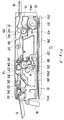
- Fig. 2 is a schematic longitudinal cross sectional view showing the whole composition of an electrostatic transfer type copying machine 11 of a first preferred embodiment according to the present invention.
- a document table 20 for arranging a document 21 thereon is arranged movably in a horizontal direction on the upper surface of a body 12 of the copying machine 11, and a document cover 13 for covering and pressing down the document 21 on the document table 20 is arranged on the document table 20.
- an exposure optical system comprising a light source 22 for illuminating the document 21 arranged on the document table 20, and a lens 23 such as a SelfocTM lens for focusing light reflected by the document 21 onto an exposure area 25 of a surface of a photoconductive drum 24 arranged under the lens 23 so as to form an electrostatic latent image corresponding to the image of the document 21 thereon.
- the photoconductive drum 24 is rotated in a direction indicated by an arrow R as shown in Fig. 2 by a driving unit (not shown), synchronous with the aforementioned movement of the document table 20, i.e., the scan operation for scanning the document 21.
- a corona charger 30 for electrifying the surface of the photoconductive drum 24
- a development unit 26 comprising a magnetic brush 26a for supplying a toner to the surface of the photoconductive drum 24 so as to develop the electrostatic latent image in a visible toner image therewith
- a transfer charger 27 for electrifying the surface of the photoconductive drum 24 and a copying paper 28 so as to transfer to visible toner image formed on the surface of the photoconductive drum 24 onto the copying paper 28, a separating nail member 36 for separating the copying paper 28 on which the toner image is transferred from the photoconductive drum 24, and a cleaning unit 29 for removing the toner remaining on the surface of the photoconductive drum 24
- a handle 18 for carrying the body 12 is arranged on a side portion 14b of the body 12, and a paper feeding tray 31 for accommodating the copying papers 28 is arranged under the handle 18.
- a paper drawing roller 32 for drawing the copying paper 28 loaded on the paper feeding tray 31 one by one is arranged above a left end portion of the tray 31.
- a paper feeding roller 33 and friction plate 34 for ensuring that only one sheet of copying paper 28 is fed at a time are arranged on the left side of a paper pick up roller 32.
- a pair of resist rollers 35 for transporting the copying paper 28 to a transfer area TA positioned between the photoconductive drum 24 and the transfer charger 27 are arranged on the left side of the paper feeding roller 33.
- transportation rollers 37 for transporting the copying paper 28 separated from the photoconductive drum 24 to a guide member 38, and the guide member 38 for guiding the copying paper 28 transported by the transportation rollers 37 to a fixing unit 39 which is arranged on the left side thereof.
- the fixing unit 39 for fixing the toner image transferred onto the copying paper 28 comprises an upper heating roller 40 and a lower heating roller 42.
- the upper heating roller 40 comprises a metallic cylinder, and is arranged rotatably in a horizontal direction.
- the upper heating roller 40 further comprises a heating lamp 41 used as a heating source inside thereof, and a coating layer of a resin such as Teflon® formed on the outer surface of the upper heating roller 40.
- the lower heating roller 42 has a coating layer made of a material such as silicon rubber, having a hardness of approximately 40° which is prescribed by the aforementioned JIS K6301 - 1975.
- the temperature of the upper heating roller 40 is measured by a thermistor 43 which is arranged above the roller 40 in contact therewith, and the temperature thereof is controlled by a control unit (not shown) so as to keep it at a predetermined room temperature.
- a paper discharging opening 15 is formed in an opposite side portion 14a to the side portion 14b of the body 12, and a paper discharging tray 16 for receiving the copying paper 28 after the toner image is fixed by the fixing unit 39 is arranged detachable from the paper discharging opening 15.
- the document 21 arranged on the document table 20 is illuminated by a light source 22, and light reflected by the document 21 is transmitted onto the exposure area 25 of the surface of the photoconductive drum 24 through the lens 23 so that the image of the document 21 is formed on the exposure area 25 of the surface of the photoconductive drum 24.
- the surface of the photoconductive drum 24 is electrified by the corona charger 30 arranged on the upper stream side of the aforementioned exposure area 25, and the photoconductive drum 24 is rotated in the direction indicated by the arrow R and the light reflected by the document 21 is exposed to the exposure area 25 as described above, so that an electrostatic latent image corresponding to the image of the document 21 is formed thereon.
- the electrostatic latent image is developed in a visible toner image with a toner supplied by the magnetic brush 26a of the development unit 26, and the visible toner image is transferred onto the copying paper 28 transported from the paper feeding tray 31 through the paper pick up roller 32, the paper feeding roller 33, and a pair of resist rollers 35. Thereafter, the toner remaining on the surface of the photoconductive drum 24 is removed by the cleaning unit 29.
- the copying paper 28 is separated from the photoconductive drum 24 by the separating nail member 36, and is transported to the fixing unit 39 through the guide member 38 by the transportation roller 37. Thereafter, the toner image transferred on the copying paper 28 is fixed by the fixing unit 39, and the copying paper 28 is sent to the paper exhausting tray 16.
- the fixing temperature HT is set to be considerably lower than that of the conventional copying machine.
- the melting temperature TT of the toner such as 140°C is predetermined according to the kind of the toner to be used, and the fixing temperature HT is set so as to satisfy the following inequality (4): TT + 10 ⁇ HT ⁇ TT + 20 [°C]
- the fixing temperature HT is preferably set so as to satisfy the above inequality (4).
- the fixing temperature HT is smaller than (TT + 10) [°C]
- the toner image may not be fixed properly because of insufficient melting heat.
- the toner image can be reliably fixed onto the copying paper 28 by the fixing unit 39, and also it is confirmed that the inequality (4) is a proper range in which the toner image is properly fixed onto the copying paper 28. Furthermore, it is confirmed that rumple patterns can be prevented from occurring in the copying paper 28.
- the fixing temperature HT is set to be a lower value than that of the conventional example, in order to solve the problems as described in the description of the related art.
- the aforementioned fixing distance LH is set to be a smaller value than that of the conventional example.
- the composition of the copying machine of the present preferred embodiment has essentially the same technical problems as that of the aforementioned embodiment which are caused by heating the copying paper 28 excessively, and therefore, it is supposed that the above problems can be solved by decreasing the heating amount to be applied from the fixing unit 39 to the copying paper 28.
- the fixing time HS can be decreased by decreasing the fixing distance LH in order to solve the aforementioned technical problems.
- the aforementioned fixing distance LH has a length of approximately 3 mm because the upper heating roller 40 pinches the lower heating roller 42 made of silicon rubber. Accordingly, the following two methods for decreasing the aforementioned fixing distance LH as much as possible can be considered:
- the present inventor not only measured the fixing distance LH and the fixing time HS but also checked the occurrence of rumple patterns by varying the hardness of the surface of the lower heating roller 42 stepwise. Furthermore, the above measurement and check operation were performed by varying the fixing pressure. The result of above measurement and check operation are shown in Tables 3 and 4. The results of the above measurement and check operation shown in Table 3 were obtained under the condition of a transfer speed VP of 60 mm/sec, a fixing force WH of 78.4532 N and a fixing temperature HT of 170°C.
- the present inventors confirmed that the fixing time HS becomes 50 msec in a conventional copying machine having a transfer speed VP of 70 mm/sec and a fixing distance LH of 3.5 mm, and assumed that the maximum fixing time HS being capable of preventing rumple patterns from occurring was 50 msec.
- Tables 3 and 4 shows that various results were obtained by varying only the fixing force WH while keeping other conditions unchanged. This is because of the fact that the copying paper 28 is contracted and corrugated easily if the fixing force WH to be applied to the copying paper 28 is very small. Therefore, it is considered that rumple patterns may be caused even though the fixing time HS is set to be a relatively small value.
- the fixing force WH is preferably set to be 29.41995 N or more and the coating layer of the lower heating roller 42 is preferably made of a silicon rubber having a hardness of 40° or more, so that the fixing distance LH is set to be 2.5 mm or less.
- the copying machine of the present preferred embodiment composed thus has the same effect as that of the aforementioned first preferred embodiments.
- the transfer speed VP and the fixing speed VH are set so as to satisfy the aforementioned inequality (2) and the aforementioned transfer speed VP is set to be 60 mm/sec or less, as shown in Fig. 1 referred to in the description of the related art, the copying paper 2 is warped at a position prior to the fixing unit 4, and then, the copying paper 28 is close to the heating rollers 5 and 6 beyond a predetermined preferable fixing distance LH, and the total heat amount applied to the copying paper 2 due to direct heat transmission and heat radiation becomes too large.
- the reason why the aforementioned rumple pattern is caused by the warp of the copying paper 2 is that the copying paper 2 is not pressed on the guide member 3 properly, and thereby, the aforementioned "squeezing effect" of the guide member 3 is lowered.
- the fixing speed VH is set so as to satisfy the following inequality (6): 1.005 VP ⁇ VH ⁇ 1.02 VP.
- the fixing speed VH becomes higher than the transfer speed VP, and the copying paper 28 is tensed between the fixing unit 39 and the vicinity of the transfer charger 27 in the running direction thereof. Accordingly, the aforementioned two problems due to the warp of the copying paper 28 can be solved.
- the experiment was done under the conditions of a transfer speed VP of 60 mm/sec, a fixing temperature HT of 170°C, and a transfer force WH of 78.4532 N.
- the aforementioned increasing rate IR of the fixing speed VH is preferably in the range from 0.5% to 2.0% in order to prevent rumple patterns and mistransfer of toner image effectively.
- the distance lH which is the length of the imaginary line extending from the end portion of the guide member 38 positioned on the side of the fixing unit 39 to the outer surface of the fixing unit 39, is set to be approximately in the range from 0.1DH to 0.15DH, wherein DH is the diameter of the upper heating roller 40.
- the aforementioned distance lH is set to be a larger value, such as 0.2HD, than that of the conventional copying machine. Then, the end portion 46 of the guide member 38 is further than the position of the conventional copying machine from the outer surface of the upper heating roller 40, and therefore, the heat amount to be applied to the copying paper 28 by the heating rollers 40 and 42 is decreased.
- the sliding angle ⁇ H as shown in the drawings is set to be approximately 8°. Namely, the guide member 38 is inclined at a larger angle than that of the conventional copying machine so that the end portion 46 is positioned at an upper position so that the end portion 46 is positioned at an upper position than that of the conventional copying machine, as shown in Fig. 3. Accordingly, even though the end portion 46 of the guide member 38 is further than that of the conventional copying machine from the outer surface of the upper heating roller 40, the guide member 39 has essentially the same squeezing effect on the copying paper 28 as that of the conventional copying machine.
- the distance lH is in the following range in order to prevent rumple patterns and real rumples from forming: 0.2DH ⁇ lH ⁇ 0.4DH
- the above range varies when various values for the sliding angle ⁇ H are set. Accordingly, in the copying machine 11 having a transfer speed VP of 60 mm/sec which is used in respective above preferred embodiments, the distance lH is set preferably to be 0.2DH or more. In the copying machine composed thus, an essentially similar effect can be obtained as that of the aforementioned preferred embodiments.
- the present inventor made various copying machines 11 compound as described above, having the parameters of the following range, under the condition of a transfer speed VP of 50 mm/sec, a melting temperature TT of the toner of 140°C, the fixing temperature HT of 160°C, a fixing force WH of 78.4532 N, and a diameter DH of the upper heating roller 40 of 25 mm.
- the copying machines having an independent composition are described, respectively.
- the copying machine having a proper combination of parameters set in respective aforementioned preferred embodiments may be used.
Landscapes
- Physics & Mathematics (AREA)
- General Physics & Mathematics (AREA)
- Fixing For Electrophotography (AREA)
Claims (6)
- Tonerbildfixiervorrichtung (39) für eine Bilderzeugungsmaschine, die derart betreibbar ist, daß sie ein Tonerbild von einem Bildträger (24) auf ein Blattmedium überträgt, wobei das Blattmedium mit einer Übertragungsgeschwindigkeit von 60mm/sec oder weniger läuft, wobei die Fixiervorrichtung (39) derart betreibbar ist, daß sie das übertragene Tonerbild derart erwärmt, daß es auf dem Blattmedium fixiert wird, wobei das Blattmedium mit einer Fixiergeschwindigkeit läuft, die etwas geringer ist als die Übertragungsgeschwindigkeit,
dadurch gekennzeichnet,
daß die Fixiertemperatur HT der Fixiervorrichtung im Betrieb gegeben ist durch
- Tonerbildfixiervorrichtung (39) für eine Bilderzeugungsmaschine, die derart betreibbar ist, daß sie ein Tonerbild von einem Bildträger (24) auf ein Blattmedium überträgt, wobei das Blattmedium mit einer Übertragungsgeschwindigkeit von 60mm/sec oder weniger läuft, wobei die Fixiervorrichtung (39) derart betreibbar ist, daß sie das übertragene Tonerbild derart erwärmt, daß es auf dem Blattmedium fixiert wird, und ein Paar einander gegenüber angeordneter Walzen (40,42) zum Pressen des Blattmediums in den zwischen ihnen gebildeten Spalt aufweist, dadurch gekennzeichnet, daß die Oberflächenhärte einer der Walzen (40,42) auf einen Wert von wenigstens 40° eingestellt ist, und daß die durch den Spalt zwischen den Walzen (40,42), entlang dem das Medium durch die Walzen (40,42) gepreßt wird, gemessene Fixierlänge (LH) auf einen Wert eingestellt ist, der nicht größer als 2,5mm ist.
- Tonerbildfixiervorrichtung (39) für eine Bilderzeugungsmaschine, die derart betreibbar ist, daß sie ein Tonerbild von einem Bildträger (24) auf ein Blattmedium überträgt, wobei das Blattmedium mit einer vorbestimmten Übertragungsgeschwindigkeit VP läuft, wobei die Fixiervorrichtung (39) derart betreibbar ist, daß sie das übertragene Tonerbild derart erwärmt, daß es auf dem Blattmedium fixiert wird, wobei das Blattmedium mit einer vorbestimmten Fixiergeschwindigkeit VH läuft, dadurch gekennzeichnet, daß der Wert der Fixiergeschwindigkeit die Ungleichung

- Tonerbildfixiervorrichtung (39) für eine Bilderzeugungsmaschine, die derart betreibbar ist, daß sie ein Tonerbild von einem Bildträger (24) auf ein Blattmedium überträgt, wobei das Blattmedium mit einer Übertragungsgeschwindigkeit von 60mm/sec oder weniger läuft, wobei die Fixiervorrichtung (39) derart betreibbar ist, daß sie das übertragene Tonerbild derart erwärmt, daß es auf dem Blattmedium fixiert wird, wobei das Blattmedium mit einer Fixiergeschwindigkeit läuft, die etwas geringer ist als die Übertragungsgeschwindigkeit, wobei die Fixiereinrichtung (39) ein Paar einander gegenüber angeordneter Walzen (40,42) zum Pressen des Blattmediums in den zwischen ihnen gebildeten Spalt aufweist, und eine Führungseinrichtung (38), die zum Führen des tonerbildtragenden Blattmediums zu den Walzen (40,42) vorgesehen ist, dadurch gekennzeichnet, daß der entlang des Laufwegs der Vorderkante des von der Führungseinrichtung (38) geführten Blattmediums gemessene Abstand zwischen einer den Walzen (40,42) gegenüberliegenden Kante der Führungseinrichtung (38) einerseits und den Walzen (40,42) andererseits derart eingestellt ist, daß er größer oder gleich 0,2 x DH ist, wobei DH der Durchmesser einer der Walzen (40,42) ist.
- Tonerbildfixiervorrichtung nach einem der Ansprüche 1 bis 4, bei der der Bildträger, von dem das Tonerbild übertragen wird, ein photoleitfähiger Bildträger ist, und Bilderzeugungseinrichtungen zum Erzeugen eines elektrostatischen Bildes entsprechend dem Bild eines Dokuments auf dem Träger vorgesehen sind.
- Tonerbildfixiervorrichtung nach einem der Ansprüche 1 bis 5, bei dem das Blattmedium aus Papier besteht.
Applications Claiming Priority (2)
| Application Number | Priority Date | Filing Date | Title |
|---|---|---|---|
| JP63135051A JPH01303470A (ja) | 1988-05-31 | 1988-05-31 | 複写機 |
| JP135051/88 | 1988-05-31 |
Publications (3)
| Publication Number | Publication Date |
|---|---|
| EP0345034A2 EP0345034A2 (de) | 1989-12-06 |
| EP0345034A3 EP0345034A3 (en) | 1990-02-07 |
| EP0345034B1 true EP0345034B1 (de) | 1993-04-14 |
Family
ID=15142777
Family Applications (1)
| Application Number | Title | Priority Date | Filing Date |
|---|---|---|---|
| EP89305467A Expired - Lifetime EP0345034B1 (de) | 1988-05-31 | 1989-05-31 | Fixiergerät für ein Tonerbild in einer Bilderzeugungsmaschine |
Country Status (4)
| Country | Link |
|---|---|
| US (1) | US4914484A (de) |
| EP (1) | EP0345034B1 (de) |
| JP (1) | JPH01303470A (de) |
| DE (1) | DE68905962T2 (de) |
Families Citing this family (9)
| Publication number | Priority date | Publication date | Assignee | Title |
|---|---|---|---|---|
| JPH03177870A (ja) * | 1989-12-07 | 1991-08-01 | Toshiba Corp | 定着装置 |
| JPH05107964A (ja) * | 1991-10-18 | 1993-04-30 | Sharp Corp | 定着装置 |
| US5241354A (en) * | 1992-04-14 | 1993-08-31 | Eastman Kodak Company | Symmetrically flexible sheet stripping apparatus |
| US5319426A (en) * | 1992-12-02 | 1994-06-07 | Eastman Kodak Company | Image forming apparatus having improved fusing consistency |
| JPH08110721A (ja) * | 1994-10-12 | 1996-04-30 | Fuji Xerox Co Ltd | 画像定着装置 |
| JP2001154436A (ja) | 1999-11-24 | 2001-06-08 | Sharp Corp | 画像形成装置 |
| US7020431B2 (en) * | 2002-10-24 | 2006-03-28 | Canon Kabushiki Kaisha | Image forming apparatus with different transport speeds in transfer unit and fixing unit |
| JP6876467B2 (ja) * | 2017-03-02 | 2021-05-26 | 株式会社東芝 | 画像形成装置 |
| JP6916032B2 (ja) * | 2017-04-21 | 2021-08-11 | 株式会社東芝 | 画像形成装置 |
Family Cites Families (20)
| Publication number | Priority date | Publication date | Assignee | Title |
|---|---|---|---|---|
| US3588445A (en) * | 1969-01-17 | 1971-06-28 | Xerox Corp | Fuser control circuit |
| JPS5637549B2 (de) * | 1971-12-03 | 1981-09-01 | ||
| US3706491A (en) * | 1971-12-16 | 1972-12-19 | Ibm | Fuser roll cleaning method and apparatus for performing it |
| US4019024A (en) * | 1972-03-29 | 1977-04-19 | Ricoh Co., Ltd. | Roller for fixing electrophotographic toner images and method of producing the same |
| US3851144A (en) * | 1973-05-24 | 1974-11-26 | Xerox Corp | Feedback fuser for 730s |
| US3833790A (en) * | 1973-07-05 | 1974-09-03 | Xerox Corp | Heated pressure fusing system |
| JPS524845A (en) * | 1975-06-30 | 1977-01-14 | Ricoh Co Ltd | Pressure stabilizing system |
| JPS5642682Y2 (de) * | 1976-11-05 | 1981-10-06 | ||
| US4232959A (en) * | 1978-09-05 | 1980-11-11 | Eastman Kodak Company | Toner image fusing apparatus |
| JPS55131145A (en) * | 1979-03-30 | 1980-10-11 | Anritsu Corp | Manufacture of solder |
| JPS5670581A (en) * | 1979-11-15 | 1981-06-12 | Canon Inc | Fixing device |
| JPS573943A (en) * | 1980-06-06 | 1982-01-09 | Taisei Corp | Joint work of pillar beam in precast reinforced concrete structure |
| US4318612A (en) * | 1980-07-10 | 1982-03-09 | International Business Machines Corporation | Hot roll fuser temperature control |
| US4319874A (en) * | 1980-10-28 | 1982-03-16 | Xerox Corporation | Fuser apparatus and control therefore |
| US4780742A (en) * | 1984-07-30 | 1988-10-25 | Canon Kabushiki Kaisha | Image quality improving process and apparatus and sheet usable therewith |
| US4812873A (en) * | 1986-09-09 | 1989-03-14 | Minolta Camera Kabushiki Kaisha | Heat fixing unit in an electrophotographic copying apparatus |
| JPH0758411B2 (ja) * | 1986-09-22 | 1995-06-21 | キヤノン株式会社 | トナー像の定着方法 |
| JPS6398682A (ja) * | 1986-10-16 | 1988-04-30 | Ricoh Co Ltd | 記録装置における定着装置 |
| JP2755323B2 (ja) * | 1986-10-24 | 1998-05-20 | 株式会社リコー | 定着方法 |
| US4843214A (en) * | 1987-05-07 | 1989-06-27 | Ricoh Company, Ltd. | Heat roll type arrangement for electrostatic recording apparatus |
-
1988
- 1988-05-31 JP JP63135051A patent/JPH01303470A/ja active Pending
-
1989
- 1989-05-25 US US07/356,947 patent/US4914484A/en not_active Expired - Lifetime
- 1989-05-31 DE DE8989305467T patent/DE68905962T2/de not_active Expired - Lifetime
- 1989-05-31 EP EP89305467A patent/EP0345034B1/de not_active Expired - Lifetime
Also Published As
| Publication number | Publication date |
|---|---|
| DE68905962D1 (de) | 1993-05-19 |
| EP0345034A2 (de) | 1989-12-06 |
| JPH01303470A (ja) | 1989-12-07 |
| EP0345034A3 (en) | 1990-02-07 |
| DE68905962T2 (de) | 1993-07-22 |
| US4914484A (en) | 1990-04-03 |
Similar Documents
| Publication | Publication Date | Title |
|---|---|---|
| US5138390A (en) | Cleaning sheet for fixating rotational member and image forming apparatus having fixating rotational member | |
| EP0487265B1 (de) | Fixiervorrichtung mit selektierbarem Fertigbearbeitungszustand | |
| US5319430A (en) | Fuser mechanism having crowned rolls | |
| KR940005136B1 (ko) | 운반회전부재 및 운반장치 | |
| US4563073A (en) | Low mass heat and pressure fuser and release agent management system therefor | |
| EP0485123B1 (de) | Vorrichtung zur Beseitigung von Blattwellungen | |
| US5546173A (en) | Fixing device | |
| US5689788A (en) | Heat and pressure roll fuser with substantially uniform velocity | |
| EP0345034B1 (de) | Fixiergerät für ein Tonerbild in einer Bilderzeugungsmaschine | |
| US5689789A (en) | Uniform nip velocity roll fuser | |
| JPH03233586A (ja) | 定着装置 | |
| US4937631A (en) | Fusing unit for a copy machine | |
| US5422710A (en) | Sheet discharging device for use in an image forming apparatus | |
| US5298959A (en) | Image forming apparatus with re-feeding means | |
| US4375327A (en) | Roller fixing device | |
| US5950061A (en) | Fixing member having an inner elastic layer with a surface roughness | |
| US4566778A (en) | Pressure fixing device | |
| US5937255A (en) | Fuser having release agent supply means comprising fluororesin fibers | |
| US4092099A (en) | Copier paper delivery means in a heat-fixing device of a copying machine | |
| EP0784247A2 (de) | Fixiervorrichtung | |
| JP2547396B2 (ja) | 定着装置 | |
| US5708951A (en) | Toner image fixing device | |
| JPH08185071A (ja) | 画像形成装置 | |
| US5130753A (en) | Electrophotographic copying apparatus | |
| JPH08160789A (ja) | 電子写真系プリンタの定着装置 |
Legal Events
| Date | Code | Title | Description |
|---|---|---|---|
| PUAI | Public reference made under article 153(3) epc to a published international application that has entered the european phase |
Free format text: ORIGINAL CODE: 0009012 |
|
| AK | Designated contracting states |
Kind code of ref document: A2 Designated state(s): DE FR GB |
|
| PUAL | Search report despatched |
Free format text: ORIGINAL CODE: 0009013 |
|
| AK | Designated contracting states |
Kind code of ref document: A3 Designated state(s): DE FR GB |
|
| 17P | Request for examination filed |
Effective date: 19900327 |
|
| 17Q | First examination report despatched |
Effective date: 19911212 |
|
| GRAA | (expected) grant |
Free format text: ORIGINAL CODE: 0009210 |
|
| AK | Designated contracting states |
Kind code of ref document: B1 Designated state(s): DE FR GB |
|
| REF | Corresponds to: |
Ref document number: 68905962 Country of ref document: DE Date of ref document: 19930519 |
|
| ET | Fr: translation filed | ||
| PLBE | No opposition filed within time limit |
Free format text: ORIGINAL CODE: 0009261 |
|
| STAA | Information on the status of an ep patent application or granted ep patent |
Free format text: STATUS: NO OPPOSITION FILED WITHIN TIME LIMIT |
|
| 26N | No opposition filed | ||
| REG | Reference to a national code |
Ref country code: GB Ref legal event code: IF02 |
|
| PGFP | Annual fee paid to national office [announced via postgrant information from national office to epo] |
Ref country code: DE Payment date: 20080605 Year of fee payment: 20 |
|
| PGFP | Annual fee paid to national office [announced via postgrant information from national office to epo] |
Ref country code: GB Payment date: 20080604 Year of fee payment: 20 |
|
| REG | Reference to a national code |
Ref country code: GB Ref legal event code: PE20 Expiry date: 20090530 |
|
| PG25 | Lapsed in a contracting state [announced via postgrant information from national office to epo] |
Ref country code: GB Free format text: LAPSE BECAUSE OF EXPIRATION OF PROTECTION Effective date: 20090530 |
|
| PGFP | Annual fee paid to national office [announced via postgrant information from national office to epo] |
Ref country code: FR Payment date: 20080514 Year of fee payment: 20 |