EP0344703A2 - Adapter for a three-phase power rail - Google Patents
Adapter for a three-phase power rail Download PDFInfo
- Publication number
- EP0344703A2 EP0344703A2 EP89109710A EP89109710A EP0344703A2 EP 0344703 A2 EP0344703 A2 EP 0344703A2 EP 89109710 A EP89109710 A EP 89109710A EP 89109710 A EP89109710 A EP 89109710A EP 0344703 A2 EP0344703 A2 EP 0344703A2
- Authority
- EP
- European Patent Office
- Prior art keywords
- contact
- adapter
- control shaft
- switching
- recess
- Prior art date
- Legal status (The legal status is an assumption and is not a legal conclusion. Google has not performed a legal analysis and makes no representation as to the accuracy of the status listed.)
- Ceased
Links
Images

Classifications
-
- H—ELECTRICITY
- H01—ELECTRIC ELEMENTS
- H01R—ELECTRICALLY-CONDUCTIVE CONNECTIONS; STRUCTURAL ASSOCIATIONS OF A PLURALITY OF MUTUALLY-INSULATED ELECTRICAL CONNECTING ELEMENTS; COUPLING DEVICES; CURRENT COLLECTORS
- H01R25/00—Coupling parts adapted for simultaneous co-operation with two or more identical counterparts, e.g. for distributing energy to two or more circuits
- H01R25/14—Rails or bus-bars constructed so that the counterparts can be connected thereto at any point along their length
- H01R25/142—Their counterparts
-
- H—ELECTRICITY
- H01—ELECTRIC ELEMENTS
- H01R—ELECTRICALLY-CONDUCTIVE CONNECTIONS; STRUCTURAL ASSOCIATIONS OF A PLURALITY OF MUTUALLY-INSULATED ELECTRICAL CONNECTING ELEMENTS; COUPLING DEVICES; CURRENT COLLECTORS
- H01R29/00—Coupling parts for selective co-operation with a counterpart in different ways to establish different circuits, e.g. for voltage selection, for series-parallel selection, programmable connectors
Abstract
Description
Die Erfindung betrifft einen Adapter für eine dreiphasige Stromentnehmeschiene nach dem Oberbegriff des Anspruchs 1.The invention relates to an adapter for a three-phase current extraction rail according to the preamble of
Ein Adapter dieser Art ist aus der DE-OS 28 10 618 bekannt. Dort ist als Sperrvorrichtung im wesentlichen ein Schieber mit einem federnd abgestützten Teleskopeinsatz vorgesehen, der zwischen den beiden Schaltwellen verschiebbar ist und eine kraftschlüssige Sperrung der Schaltwellen gestattet. Diese Sperrvorrichtung ist verhältnismäßig kompliziert aufgebaut und führt zu einer verhältnismäßig großen Baulänge.An adapter of this type is known from DE-OS 28 10 618. There is essentially provided as a locking device a slide with a resiliently supported telescopic insert, which is displaceable between the two switching shafts and allows a non-positive locking of the switching shafts. This locking device is relatively complicated and leads to a relatively large length.
Nach der DE-OS 32 14 911 ist es bekannt, in einem Adapter eine Sperreinrichtung mit einer federbelasteten Klinke zu versehen, die die Sperrvorrichtung in ihrer unwirksamen Lage hält, wenn der Adapter nicht in die Stromentnahmeschiene eingesetzt ist. In der eingesetzten Lage taucht die Klinke aus einer Rastausnehmung der Sperrvorrichtung auf und erlaubt eine Verdrehung eines Stellglieds der Sperrvorrichtung in eine Feststellage.According to DE-OS 32 14 911 it is known to provide a locking device in an adapter with a spring-loaded pawl, which holds the locking device in its inoperative position when the adapter is not inserted into the power take-off rail. In the inserted position, the pawl emerges from a locking recess of the locking device and allows an actuator of the locking device to be rotated into a locking position.
Nach der DE-OS 34 15 899 ist ein Adapter bekannt, der eine einfedernde Endkontaktzunge aufweist.According to DE-OS 34 15 899 an adapter is known which has a resilient end contact tongue.
Aufgabe der Erfindung ist es, einen Adapter nach dem Oberbegriff des Anspruchs 1 anzugeben, dessen Sperrvorrichtung einfacher aufgebaut ist und keine große Baulänge erfordert.The object of the invention is to provide an adapter according to the preamble of
Die Lösung dieser Aufgabe ist in Anspruch 1 angegeben.The solution to this problem is specified in
Die Wippe nach der Erfindung bedarf keiner Zusatzelemente wie eines Teleskopiereinsatzes oder einer Feder. Da die Wippe von der Seite aus mit ihren Vorsprüngen in die Ausnehmungen der Schaltwellen eingreift, führt sie zu keiner vergrößerten Baulänge, gestattet vielmehr die Ausnützung einer ohnehin vorhandenen, bisher nicht genutzten Baubreite.The rocker according to the invention does not require any additional elements such as a telescopic insert or a spring. Since the rocker engages with the projections in the recesses of the selector shafts from the side, it leads to no increased length, rather allows the use of an existing, previously unused width.
Die Breite der Aufnahmekanäle bekannter Stromentnahmeschienen ist unterschiedlich; sie variiert beispielsweise zwischen 14 mm und 15 mm. Auch variieren die Abstände der beiden zueinander parallelen Ebenen, in denen die Leiter angeordnet sind, beispielsweise um 1 mm. Die bekannten Adapter haben den Nachteil, daß sie trotz der relativ geringfügigen Abweichungen jeweils nur zu einer dieser Stromentnahmeschienen exakt passen, weil entweder ihr Eingreifteil zu breit ist gegenüber dem Aufnahmekanal der jeweils anderen Stromentnahmeschiene oder die ausschwenkbaren Kontaktzungen nicht störungsfrei mit den jeweiligen Leitern in Verbindung gebracht werden können. Ferner sind auch die Erdschutzleiter unterschiedlich angebracht, beispielsweise ist bei einer Stromentnahmeschiene der Erdschutzleiter in der Nähe der Öffnung des Aufnahmekanals angeordnet, während bei einer anderen Stromentnahmeschiene der Erdschutzleiter im Boden des Aufnahmekanals angeordnet ist. Schließlich sind auch die das polgerechte Einsetzen des Adapters erzwingenden Vorsprünge und ausnehmungen so unterschiedlich, daß die zu den einzelnen Stromschienen passenden Adapter nicht in eine jeweils andere Stromschiene eingesetzt werden können.The width of the receiving channels of known current drain rails is different; for example, it varies between 14 mm and 15 mm. The distances between the two mutually parallel planes in which the conductors are arranged also vary, for example by 1 mm. The known adapters have the disadvantage that, despite the relatively slight deviations, they only fit exactly to one of these current drain rails, because either their engaging part is too wide compared to the receiving channel of the other current drain rail or the swing-out contact tongues are not properly connected to the respective conductors can be. Furthermore, the earth protection conductors are also attached differently, for example in the case of one current extraction rail the earth protection conductor is arranged in the vicinity of the opening of the receiving channel, while in another current extraction rail the earth protection conductor is arranged in the bottom of the receiving channel. Finally, the projections and recesses which force the correct insertion of the adapter are also so different that the adapters matching the individual busbars cannot be inserted into a different busbar.
Um den Adapter für unterschiedlich ausgebildete dreiphasige Stromentnahmeschienen verwenden zu können, ist er daher entsprechend Anspruch 2 ausgebildet.In order to be able to use the adapter for differently designed three-phase current extraction rails, it is therefore designed in accordance with
Eine Vereinfachung des Aufbaus des Adapters wird durch Anspruch 3 erzielt.A simplification of the construction of the adapter is achieved by
Die Aufnahme der Klinke im Gehäuse wird durch die Ausbildung gemäß Anspruch 4 vereinfacht, insbesondere auch durch Anspruch 5.The inclusion of the pawl in the housing is simplified by the design according to
Die Fertigung und der Zusammenbau des Adapters werden durch die Ausbildung nach Anspruch 6 erleichtert. Um der zweiten Schaltwelle eine definierte Ausgangslage zu geben, ist bevorzugt eine Ausbildung nach Anspruch 7 vorgesehen, bevorzugt in den konstruktiv einfachen Gestaltungen nach Anspruch 8 oder 9.The manufacture and assembly of the adapter are facilitated by the training according to
Eine besonders einfache Führung der zweiten Schaltwelle ist in Anspruch 10 angegeben.A particularly simple guidance of the second selector shaft is specified in
In der folgenden Beschreibung wird ein Ausführungsbeispiel der Erfindung unter Bezugnahme auf die Zeichnungen näher erläutert. Die Zeichnungen zeigen in
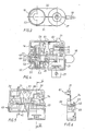
- Fig. 1 eine Frontansicht des Adapters und Frontansichten dreier unterschiedlicher Stromentnahmeschienen,
- Fig. 2 eine Seitenansicht des Adapters nach Fig. 1,
- Fig. 3 eine Ansicht des Adapters nach Fig. 2, von unten,
- Fig. 4 eine Seitenansicht entsprechend Fig. 2, jedoch bei Abnahme einer Halbschale des Gehäuses,
- Fig. 5 eine Ansicht auf die Innenseite einer Halbschale des Gehäuses,
- Fig. 6 eine Ansicht nach der Schnittlinie VI-VI in Fig. 5,
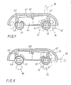
- Fig. 7 und 8 Draufsichten auf die Sperrvorrichtung für die Schaltwellen bei zwei verschiedenen Schaltstellungen.
- 1 is a front view of the adapter and front views of three different current drain rails,
- 2 is a side view of the adapter of FIG. 1,
- 3 is a view of the adapter of FIG. 2, from below,
- 4 shows a side view corresponding to FIG. 2, but with the removal of a half-shell of the housing,
- 5 is a view of the inside of a half-shell of the housing,
- 6 is a view along the section line VI-VI in Fig. 5,
- Fig. 7 and 8 plan views of the locking device for the shift shafts in two different switching positions.
Wie Fig. 1 zeigt, kann der Adapter 3 in drei unterschiedliche Stromentnahmeschienen 1, 1′, 1˝ eingesetzt werden. Jede Stromentnahmeschiene 1, 1′, 1˝ ist mit einem Aufnahmekanal 2 versehen, in den ein Eingreifteil 4 des Adapters 3 eingesetzt werden kann. Zu beiden Seiten des Aufnahmekanals 2 ist ein Isolierstoffprofil 5 eingesetzt, das je zwei Leiter 6, 7′ bzw. 7, 7˝ trägt. Die Leiter 6, 7, 7′, 7˝ sind ein Nulleiter 6 und drei Phasenleiter 7, 7′und 7˝. Am Boden des Aufnahmekanals 2 der Stromentnahmeschiene 1 ist ein Erdschutzleiter 8 angeordnet. Bei der Stromentnahmeschiene 1˝ ist ein Erdschutzleiter 8 an einer Seite der Öffnung des Aufnahmekanals 2 angeordnet.As shown in Fig. 1, the
Zum polgerechten Einsetzen des Adapters 3 in die Stromentnahmeschiene 1˝ dient ein in die Stromentnahmeschiene 1˝ eingeformter Polkanal 30, in den eine Polrippe 23 an einer Schulter 11 eines Außenteils 10 des Adapters 3 einsetzbar ist. Polrippen 60 an den Stromentnahmeschienen 1 und 1′ dienen anderen Adaptern als dem nach dem Ausführungsbeispiel.A
Die Stromentnahmeschienen 1, 1′, 1˝ weisen an jeder Seite eine nach innen, d.h. zum Aufnahmekanal 2 hin, gerichtete Rippe 9 auf. Diese Rippen 9 dienen zur mechanischen Befestigung des Adapters 3. Die Befestigung erfolgt dadurch, daß nach dem Einsetzen des Eingreifteils 4 des Adapters 3 in den Aufnahmekanal 2 einer der Stromentnahmeschienen 1, 1′, 1˝ eine Schaltwelle 12 mit Hilfe eines Schalthebels 16 um 90° geschwenkt wird, wodurch zwei Halteriegel 13, 14 der Schaltwelle 12 über die Rippen 9 geschwenkt werden und so den Adapter 3 an der Stromentnahmeschiene 1, 1′ oder 1˝ festhalten.The
Beim Einsetzen des Adapters 3 in die Stromentnahmeschiene 1 oder 1′ setzt sich die (in Fig. 1 rechte) Schulter 11 des Außenteils 10 auf deren Polrippe 60, die in diesem Fall nur als Abstandhalter genutzt ist, während sich die Polrippe 23 des Adapters 3 auf der Außenseite einer (in Fig. 1 linken) Rippe 9 abstützt. Beim Einsetzen des Adapters 3 in die Stromentnahmeschiene 1˝ greift die Polrippe 23 des Adapters 3 in den Polkanal 30 der Stromentnahmeschiene 1˝ ein.When inserting the
In einem aus zwei Halbschalen 31 und 32 gebildeten Gehäuse des Adapters 3 sind an den Seitenwänden des Eingreifteils 4 Öffnungen vorgesehen, durch welche hindurch die Halteriegel 13 und 14 sowie Kontaktzungen 15 und 18 aus dem Eingreifteil 4 nach außen zu den Leitern 6, 7, 7′, 7˝ schwenkbar sind.In a housing of the
Wie insbesondere Fig. 2 und 4 zeigen, ist der Adapter 3 mit zwei sich zwischen den Seitenwänden des Eingreifteils 4 in Einsteckrichtung erstreckenden Schaltwellen 12 und 17 versehen. Die erste Schaltwelle 12 ist mit den Halteriegeln 13 und 14 versehen, sowie mit einer radial federnden Nullkontaktzunge 15. Die zweite Schaltwelle 17 ist mit einer Phasenkontaktzunge 18 versehen, die in einer unteren Stellung an den Phasenleiter 7 anlegbar ist und in einer oberen axialen Stellung entweder an den Phasenleiter 7′ oder an den Phasenleiter 7˝ anlegbar ist. Die zweite Schaltwelle 17 kann in einer kontaktfreien Zwischenstellung mittels eines Schaltkopfes 19 aus einer unteren axialen Endstellung in eine obere axiale Endstellung um den Abstand zweier Phasenleiter 7, 7˝ axial verschoben werden. Damit die Phasenkontaktzunge 18 in der oberen axialen Endstellung ohne Schwierigkeiten mit den Phasenleitern 7˝ oder 7′ der verschiedenen Stromentnahmeschienen 1, 1′ und 1˝ verbunden wer den kann, aht die zweite Schaltwelle 17 in der oberen axialen Endstellung beim Ausschwenken der Phasenkontaktzunge 18 ein axiales Spiel von bis zu 1 mm. Zur Ermöglichung dieses axialen Spiels und zur präzisen Führung der zweiten Schaltwelle 17 ist diese mit einem Führungsteil 48 versehen, das verschwenkbar und in der Zwischenstellung der zweiten Schaltwelle 17 axial verschiebbar in einer Kulissenführung 49 geführt ist. Diese Kulissenführung 49 ist, wie die Fig. 4 und 5 zeigen, in die Halbschalen 31 und 32 eingeformt.
Leiter eines in einem Zugentlastungsteil 27 mittels einer Klemmschraube 28 gehaltenen Kabels 29 können mit Hilfe einer Erdkontaktklemme 24 an eine einfedernde Erdkontaktzunge 21 und an einfedernde Erdkontaktlappen 22, mit Hilfe einer Nullkontaktklemme 25 an die Nullkontaktzunge 15 und mit Hilfe einer Phasenkontaktklemme 26 an die Phasenkontaktzunge 18 angeschlossen werden. Wie Fig. 4 zeigt, ist lediglich die Halbschale 32 zu entfernen, um sämtliche Kontaktklemmen 24, 25, 26 frei zugänglich zu machen. Alle beweglichen Teile des Adapters 3 sind in die andere Halbschale 31 einsetzbar und mittels einer einklippbaren Halterung 39 festlegbar. Nach dem Anschließen der Leiter an den Klemmen 24, 25, 26 ist lediglich die Halbschale 32 mittels dreier Befestigungsschrauben zu befestigen (vgl. Fig. 2).2 and 4 in particular, the
Conductors of a
Damit ein zuverlässiger Kontakt des Adapters 3 mit dem Erdschutzleiter 8 der Stromentnahmeschiene 1 und der Stromentnahmeschiene 1˝ hergestellt werden kann, ist der Adapter 3 mit den einfedernden Erdkontaktlappen 22 versehen, die durch Öffnungen in einer Seitenwand des Eingreifteils 4 greifen und seitlich vorstehen und überdies an der oberen Seite des Eingreifteils 4 mit der in das Eingreifteil 4 einfedernden Endkontaktzunge 21 versehen.So that a reliable contact of the
Beim Einsetzen des Adapters 3 in die Stromentnahmeschiene 1 legt sich die Erdkontaktzunge 21 an deren Erdschutzleiter 8 an. Dabei werden die Erdkontaktlappen 22 in das Eingreifteil 4 gedrückt.When the
Beim Einsetzen des Adapters 3 in die Stromentnahmeschiene 1˝ legen sich die Erdkontaktlappen 22 an deren Erdschutzleiter 8 an der Seite der Öffnung von dessen Aufnahmekanal 2 an. Dabei wird die Erdkontaktzunge 21 in das Eingreifteil 4 gedrückt.When the
Die seitlich vorstehenden Erdkontaktlappen 22 und die Erdkontaktzunge 21 sind aus einem mehrfach abgewinkelten und mit der Erdkontaktklemme 24 versehen Blechteil gebildet, das von Haltebolzen 61, die an der Halbschale 31 angeformt sind, so gehalten wird, daß sowohl ein Schenkel 62, der die Erdkontaktzunge 21 trägt, als auch eine Schenkel, der die seitlich vorstehenden Erdkontaktlappen 22 trägt, anch innen einfedern können. Neben aus Fig. 5 ersichtlichen Durchlässen 38 für die Erdkontaktlappen 22 befinden sich hinterschnittene Leisten 65, hinter welche federnde Lappen der Halterung 39 einrasten können.The laterally projecting
Die Sperrvorrichtung für die beiden Schaltwellen 12 und 17 besteht aus einer insbesondere aus den Fig. 7 und 8 ersichtlichen Wippe 41, welche um eine zu den Achsen der Schaltwellen 12 und 17 parallele Achse 40 um weniger als 15° schwenkbar in der Halbschale 31 gelagert ist. Die Wippe 41 ist in einer schlitzartigen Tasche 36 gelagert, die in der Halbschale 31 eingeformt ist. Die Wippe 41 hat an ihren ausschwenkbaren Enden gerundete Vorsprünge 42 und 43, die mit Ausnehmungen 44 und 45 in den Schaltwellen 12 und 17 so zusammenwirken, daß in Anschlußposition der ersten Schaltwelle 12 deren Ausnehmung 44 zur Aufnahme des Vorsprunges 42 bereit ist, so daß bei Drehen der zweiten Schaltwelle 17 deren Ausnehmung 45 mit einer ihrer Seitenwände den anderen Vorsprung 43 aus seiner Sperrstellung herausdrückt und die Wippe 41 so verschwenkt, daß der erste Vorsprung 42 in die Ausnehmung 44 der ersten Schaltwelle 12 eingreift und diese sperrt und in der kontaktfreien Zwischenstellung der zweiten Schaltwelle 17 deren Ausnehmung 45 zur Aufnahme des gerundeten Vorsprungs 43 bereitsteht. Die Tasche 36 ist unter der Oberseite einer Schulter 11 des Außenteils 10 angeordnet. Im mittleren Bereich der Tasche 36 ist ein die Achse 40 definierender Vorsprung angeformt, der zur kippbaren Abstützung der Wippe 41 in eine U-förmige Aussparung 47 im Rücken der Wippe 41 ein greift.The locking device for the two
Wie insbesondere die Fig. 4 zeigt, steht die zweite Schaltwelle 17 unter der Wirkung einer Rückstellfeder 52, die bestrebt ist, die Schaltwelle 17 in die dargestellte untere axiale Endstellung zu drücken. Die Rückstellfeder 52 ist in einer Höhlung des Schaltkopfs 19 untergebracht. Der Schaltkopf 19 ist starr mit der zweiten Schaltwelle 17 verbunden. Die Rückstellfeder 52 stützt sich einerseits an einem eingesprengten Schaltkopfdeckel 53 ab und andererseits an einem kolbenartigen Druckteil 50, das sich seinerseits über zwei durch eine obere Wand des Schaltkopfes 19 hindurchgeführte Beine 51 an einer Wand des Gehäuses abstützt. Die Beine 51 ragen um die Länge des Verstellweges des Schaltkopfes 19 über die obere Wand des Schaltkopfes 19 hervor. Beim Hochschieben des Schaltkopfes 19 wird dieser bis zu einem unteren Greifrand in das Außenteil 10 des Gehäuses hineingedrückt, während das kolbenartige Druckteil 50 relativ zum Gehäuse in seiner Stellung verharrt.As shown in FIG. 4 in particular, the
Die zweite Schaltwelle 17 mit der Phasenkontaktzunge 18, der Phasenkontaktklemme 26, dem hohlen Schaltkopf 19, der Rückstellfeder 52 und dem Druckteil 50 bilden eine Montageeinheit, die in die Halbschale 31 eingesetzt und von einer Stegwand der Halterung 39 gehalten wird.The
Claims (10)
a1) ein in den Aufnahmekanal (2) polgerecht einsetzbares oberes Eingreifteil (4), aus dessen Seitenwänden durch Öffnungen hindurch wenigstens ein Halteriegel (13, 14) und Kontaktzungen (15, 18) herausschwenkbar sind und
a2) ein unteres breiteres Außenteil (10)
aufweist.
b1) die erste Schaltwelle (12) mit wenigstens einem radial vorstehenden, über eine Rippe (9) der Stromentnahmeschiene (1; 1′; 1˝) zu schwenkenden Halteriegel (13, 14) und wenigstens einer radial vorstehenden, in Kontakt mit dem Nulleiter (6) zu schwenkenden Null-Kontaktzunge (15) versehen ist und mittels eines ersten Stellglieds (16) in eine Einsetz- und Entnahmeposition und in eine Verriegelungs- und Kontaktposition verstellbar ist und von denen
b2) die zweite Schaltwelle (17) mit einer radial vorstehenden, wahlweise in Kontakt mit einem der Phasenleiter (7, 7′, 7˝) zu schwenkenden Phasenkontaktzunge (18) versehen ist und mittels eines zweiten Stellglieds (19) in eine kontaktfreie Zwischenstellung und in eine der Phasenkontakstellungen verstellbar ist,
wobei in der kontaktfreien Zwischenstellung der zweiten Schaltwelle (17) eine Ausnehmung (45) in der zweiten Schaltwelle (17) zur Aufnahme eines Vorsprungs (43) an einem Sperrglied (41) bereitsteht,
dadurch gekennzeichnet, daß das Sperrglied (41) eine im Gehäuse (4, 10) um eine mittlere, zu den Achsen der Schaltwellen (12, 17) parallele Achse (40) schwenkbar gelagerte Wippe (41) ist, die an ihren Enden mit je einem Vorsprung (42, 43) versehen ist und daß diese Vorsprünge (42, 43) mit je einer Ausnehmung (44, 45) in den Schaltwellen (12, 17) derart zusammenwirken, daß in der Verriegelungs- und Kontaktposition der ersten Schaltwelle (12), deren Ausnehmung (44) zur Aufnahme des ihr zugeordneten ersten Vorsprungs (42) bereit steht und bei Drehen der zweiten Schaltwelle (17) deren Ausnehmung (45) den ihr zugeordneten zweiten Vorsprung (43) aus sich herausdrückt und den ersten Vorsprung (42) in die Ausnehmung (44) der ersten Schaltwelle (12) hineindrückt.
a1) an upper engagement part (4) which can be inserted in the receiving channel (2) with the correct polarity, from the side walls of which at least one retaining bar (13, 14) and contact tongues (15, 18) can be pivoted out and
a2) a lower, wider outer part (10)
having.
b1) the first control shaft (12) with at least one radially projecting, via a rib (9) of the current take-off rail (1; 1 '; 1˝) to be pivoted retaining bar (13, 14) and at least one radially projecting, in contact with the neutral conductor (6) to be pivoted zero contact tongue (15) and by means of a first actuator (16) in an insertion and removal position and in a locking and contact position is adjustable and of which
b2) the second control shaft (17) is provided with a radially projecting, optionally in contact with one of the phase conductors (7, 7 ', 7˝) to be pivoted phase contact tongue (18) and by means of a second actuator (19) in a contact-free intermediate position and is adjustable in one of the phase contact positions,
wherein in the non-contact intermediate position of the second control shaft (17) there is a recess (45) in the second control shaft (17) for receiving a projection (43) on a locking member (41),
characterized in that the locking member (41) is a rocker (41) which is pivotally mounted in the housing (4, 10) about a central axis (40) parallel to the axes of the selector shafts (12, 17) and which has ends at each end is provided with a projection (42, 43) and that these projections (42, 43) each have a recess (44, 45) in the selector shafts (12, 17) in such a way that in the locking and contact position of the first selector shaft (12 ), the recess (44) of which is ready to receive the first projection (42) assigned to it and, when the second selector shaft (17) rotates, the recess (45) pushes the second projection (43) assigned to it out and the first projection (42 ) into the recess (44) of the first control shaft (12).
Applications Claiming Priority (4)
| Application Number | Priority Date | Filing Date | Title |
|---|---|---|---|
| DE8807184U | 1988-06-01 | ||
| DE8807184U DE8807184U1 (en) | 1988-06-01 | 1988-06-01 | |
| DE19893901500 DE3901500C1 (en) | 1988-06-01 | 1989-01-19 | |
| DE3901500 | 1989-01-19 |
Publications (2)
| Publication Number | Publication Date |
|---|---|
| EP0344703A2 true EP0344703A2 (en) | 1989-12-06 |
| EP0344703A3 EP0344703A3 (en) | 1992-01-02 |
Family
ID=25876915
Family Applications (1)
| Application Number | Title | Priority Date | Filing Date |
|---|---|---|---|
| EP19890109710 Ceased EP0344703A3 (en) | 1988-06-01 | 1989-05-30 | Adapter for a three-phase power rail |
Country Status (4)
| Country | Link |
|---|---|
| EP (1) | EP0344703A3 (en) |
| DE (1) | DE3901500C1 (en) |
| DK (1) | DK265889A (en) |
| FI (1) | FI892672A (en) |
Cited By (2)
| Publication number | Priority date | Publication date | Assignee | Title |
|---|---|---|---|---|
| EP0560445A1 (en) * | 1992-03-13 | 1993-09-15 | Lumiance B.V. | An adapter |
| WO2001091249A1 (en) * | 2000-05-24 | 2001-11-29 | Zumtobel Staff Gmbh | Conductor rail system |
Families Citing this family (2)
| Publication number | Priority date | Publication date | Assignee | Title |
|---|---|---|---|---|
| DE9017281U1 (en) * | 1990-12-21 | 1991-04-11 | Semperlux Gmbh Lichttechnisches Werk, 1000 Berlin, De | |
| DE4406687C2 (en) * | 1994-03-01 | 1996-03-14 | Halloform Gmbh & Co Kg | Track adapter with phase selector |
Citations (3)
| Publication number | Priority date | Publication date | Assignee | Title |
|---|---|---|---|---|
| FR2194060A1 (en) * | 1972-07-21 | 1974-02-22 | Rotaflex Ltd | |
| FR2419602A1 (en) * | 1978-03-11 | 1979-10-05 | Erco Leuchten | ADAPTER FOR SINGLE-PHASE OR POLY-PHASE CURRENT SOCKET RAILS |
| DE3214911A1 (en) * | 1982-04-22 | 1983-10-27 | Elektra GmbH & Co KG, 4904 Enger | Adaptor for busbars |
Family Cites Families (1)
| Publication number | Priority date | Publication date | Assignee | Title |
|---|---|---|---|---|
| IT8321669V0 (en) * | 1983-04-28 | 1983-04-28 | Profilux Srl | STRUCTURE OF BIPOLAR ADAPTER FOR MULTIPOLAR ELECTRIC LINES OF THE ARMORED TYPE, PART OF INSTALLATIONS FOR INTERIOR LIGHTING. |
-
1989
- 1989-01-19 DE DE19893901500 patent/DE3901500C1/de not_active Expired
- 1989-05-30 EP EP19890109710 patent/EP0344703A3/en not_active Ceased
- 1989-05-31 DK DK265889A patent/DK265889A/en unknown
- 1989-06-01 FI FI892672A patent/FI892672A/en not_active IP Right Cessation
Patent Citations (3)
| Publication number | Priority date | Publication date | Assignee | Title |
|---|---|---|---|---|
| FR2194060A1 (en) * | 1972-07-21 | 1974-02-22 | Rotaflex Ltd | |
| FR2419602A1 (en) * | 1978-03-11 | 1979-10-05 | Erco Leuchten | ADAPTER FOR SINGLE-PHASE OR POLY-PHASE CURRENT SOCKET RAILS |
| DE3214911A1 (en) * | 1982-04-22 | 1983-10-27 | Elektra GmbH & Co KG, 4904 Enger | Adaptor for busbars |
Cited By (4)
| Publication number | Priority date | Publication date | Assignee | Title |
|---|---|---|---|---|
| EP0560445A1 (en) * | 1992-03-13 | 1993-09-15 | Lumiance B.V. | An adapter |
| WO2001091249A1 (en) * | 2000-05-24 | 2001-11-29 | Zumtobel Staff Gmbh | Conductor rail system |
| EP2026425A2 (en) | 2000-05-24 | 2009-02-18 | Zumtobel Lighting GmbH | Electricity rail system |
| EP2026425A3 (en) * | 2000-05-24 | 2010-01-06 | Zumtobel Lighting GmbH | Electricity rail system |
Also Published As
| Publication number | Publication date |
|---|---|
| EP0344703A3 (en) | 1992-01-02 |
| DK265889A (en) | 1989-12-02 |
| DK265889D0 (en) | 1989-05-31 |
| DE3901500C1 (en) | 1989-12-21 |
| FI892672A (en) | 1989-12-02 |
| FI892672A0 (en) | 1989-06-01 |
Similar Documents
| Publication | Publication Date | Title |
|---|---|---|
| EP0375088B1 (en) | Disconnecting arrangement for the main current path of a power circuit breaker | |
| DE2810681C2 (en) | Adapter for single or multi-phase power take-off rails | |
| DE2627843A1 (en) | DEVICE FOR ESTABLISHING AN ELECTRICAL CONNECTION | |
| DE2501008C2 (en) | Current collector with phase preselection device for contact bars | |
| DE19835459C2 (en) | Terminal for electrical conductors | |
| DE2322798A1 (en) | ELECTRIC SWITCH | |
| DE4433144A1 (en) | Socket with rotatable plug-in section | |
| EP3316414A1 (en) | Travel adapter which can be securely grounded | |
| DE2336216A1 (en) | ELECTRICAL CONNECTOR | |
| DE2411976C2 (en) | Adapter for single or multi-phase power take-off rails | |
| DE3214911C2 (en) | ||
| DE3901500C1 (en) | ||
| EP1523065B1 (en) | Electrical terminal | |
| EP0465883B1 (en) | Electric terminal for clamping onto a conductor rail | |
| DE2741219C3 (en) | Switch device | |
| AT391226B (en) | PLUG-IN CONTACT DEVICE FOR CONNECTING A CABLE TO A POWER RAIL, IN PARTICULAR IN A CABINET OF LOW DEPTH | |
| EP1038109B1 (en) | Electric device with a connection clip and a receiving fixture for a second electric device | |
| DE3310496A1 (en) | Device for operating actuating elements in electrical apparatuses | |
| CH653181A5 (en) | Electrical connecting element | |
| DE2739581C2 (en) | Push button | |
| DE3201169A1 (en) | DEVICE FOR CLAMPING THE ELECTRICAL LADDER, IN PARTICULAR WIRE | |
| DE4437791C1 (en) | Manually-assembled cable termination | |
| DE1665322B1 (en) | ELECTRIC COMBINATION SWITCH | |
| DE10244372C1 (en) | Position switch has sliding contact carrier provided with windows fitted with contact carriers in variable configuration | |
| DE1665322C (en) | Electric combination switch |
Legal Events
| Date | Code | Title | Description |
|---|---|---|---|
| PUAI | Public reference made under article 153(3) epc to a published international application that has entered the european phase |
Free format text: ORIGINAL CODE: 0009012 |
|
| AK | Designated contracting states |
Kind code of ref document: A2 Designated state(s): AT BE CH DE ES FR GB GR IT LI LU NL SE |
|
| PUAL | Search report despatched |
Free format text: ORIGINAL CODE: 0009013 |
|
| AK | Designated contracting states |
Kind code of ref document: A3 Designated state(s): AT BE CH DE ES FR GB GR IT LI LU NL SE |
|
| 17P | Request for examination filed |
Effective date: 19920131 |
|
| 17Q | First examination report despatched |
Effective date: 19940125 |
|
| STAA | Information on the status of an ep patent application or granted ep patent |
Free format text: STATUS: THE APPLICATION HAS BEEN REFUSED |
|
| 18R | Application refused |
Effective date: 19940924 |