EP0344432A1 - Koppeleinrichtung für einen Geschwindigkeitsregler - Google Patents
Koppeleinrichtung für einen Geschwindigkeitsregler Download PDFInfo
- Publication number
- EP0344432A1 EP0344432A1 EP89106248A EP89106248A EP0344432A1 EP 0344432 A1 EP0344432 A1 EP 0344432A1 EP 89106248 A EP89106248 A EP 89106248A EP 89106248 A EP89106248 A EP 89106248A EP 0344432 A1 EP0344432 A1 EP 0344432A1
- Authority
- EP
- European Patent Office
- Prior art keywords
- actuator
- adjusting
- piece
- coupling
- connecting piece
- Prior art date
- Legal status (The legal status is an assumption and is not a legal conclusion. Google has not performed a legal analysis and makes no representation as to the accuracy of the status listed.)
- Granted
Links
Images

Classifications
-
- B—PERFORMING OPERATIONS; TRANSPORTING
- B60—VEHICLES IN GENERAL
- B60K—ARRANGEMENT OR MOUNTING OF PROPULSION UNITS OR OF TRANSMISSIONS IN VEHICLES; ARRANGEMENT OR MOUNTING OF PLURAL DIVERSE PRIME-MOVERS IN VEHICLES; AUXILIARY DRIVES FOR VEHICLES; INSTRUMENTATION OR DASHBOARDS FOR VEHICLES; ARRANGEMENTS IN CONNECTION WITH COOLING, AIR INTAKE, GAS EXHAUST OR FUEL SUPPLY OF PROPULSION UNITS IN VEHICLES
- B60K26/00—Arrangement or mounting of propulsion-unit control devices in vehicles
- B60K26/04—Arrangement or mounting of propulsion-unit control devices in vehicles of means connecting initiating means or elements to propulsion unit
-
- F—MECHANICAL ENGINEERING; LIGHTING; HEATING; WEAPONS; BLASTING
- F02—COMBUSTION ENGINES; HOT-GAS OR COMBUSTION-PRODUCT ENGINE PLANTS
- F02D—CONTROLLING COMBUSTION ENGINES
- F02D11/00—Arrangements for, or adaptations to, non-automatic engine control initiation means, e.g. operator initiated
- F02D11/06—Arrangements for, or adaptations to, non-automatic engine control initiation means, e.g. operator initiated characterised by non-mechanical control linkages, e.g. fluid control linkages or by control linkages with power drive or assistance
Definitions
- the invention relates to a coupling device for a speed controller, in particular in motor vehicles, with components which are movable relative to one another and which can be non-positively coupled to one another and which connect an actuator of the speed controller to an adjusting device which is connected directly or indirectly to a throttle valve.
- a coupling device of this type is known from the German utility model with the number GM 77 35 209.
- a coupling device between an adjusting device for adjusting the operation of an internal combustion engine and an actuator connected to a control circuit has two components which can be displaced relative to one another and a latching device attached to one of the two components.
- the latching device has a latch which can be engaged by means of an electromagnet in a snap-in trough attached to the other of the two components.
- One component is designed as a cylinder that can be attached directly to the accelerator pedal lever.
- the other component is designed as a piston which is displaceable in the cylinder.
- the locking device is on the outer circumferential wall of the cylinder and the locking trough is arranged on the piston.
- the piston is connected to the servomotor via a rack. If the speed controller is out of operation, the adjustment device is decoupled from the actuator. When the speed controller is switched on, the bolt is pressed onto the piston surface by the electromagnet through an opening in the cylinder. The actuator drives the piston from the idle position to the cylinder until the bolt engages in the locking recess, which is determined by a switch. The driving speed can thus be regulated by the speed controller. Will the When the speed controller is switched off, the bar is pulled back out of the latching recess by a return spring after the electromagnet has been switched off, so that the driving speed can be determined again by the driver.
- a disadvantage here proves that the construction is not easy and inexpensive by the use of a bolt which can be engaged by an electromagnet and can be retrieved by a spring and that a switch must also be provided which must indicate the bolt position.
- a further disadvantage is that when the speed controller is switched on, the bolt presses on the piston and the actuator has to track the piston until the bolt engages in the locking recess, which can lead to an undesirable delay in the effect of the speed controller and increases the wear on the components.
- a coupling device is known from German utility model number GM 78 08 547, which has a pneumatic actuating element, the actuating movement of which is transmitted to a coupling rod.
- a connecting device can be connected to the coupling rod via an adjusting device.
- the connecting device is designed here as a ball socket.
- a decoupling between the adjusting element and an adjusting device connected to the connecting device is not provided, so that the adjusting element is acted upon with every movement of the adjusting device, whereby the expenditure of force for actuating the adjusting device increased and the wear of the adjusting element is increased.
- the adjusting device is constructed by a thread and a union nut, as a result of which it is difficult to precisely and quickly adjust the coupling device to a basic position of the adjusting device, since force is generated in the adjusting direction by tightening the nut.
- the invention has for its object to provide a coupling device that is simple and inexpensive to manufacture and assemble, that can be easily and quickly adapted to a given adjusting device and that decouples the actuator from the adjusting device without additional effort when the adjusting device is operated manually.
- a hollow cylindrical connecting piece is firmly connected to the actuator, that the connecting piece on the side facing away from the actuator is connected via an adjusting device with a hollow cylindrical adjusting piece, that the adjusting piece on the side facing away from the actuator has a cover with a Breakthrough, in one section of which a coupling rod is slidably mounted, that the coupling rod on its side facing the actuator has a thickening which is greater than the portion of the opening in which the coupling rod is mounted and that the coupling rod on its side facing away from the actuator Side has a connecting device that connects the coupling rod with the adjusting device.
- a hollow cylindrical connecting piece is firmly connected to the actuator, because the actuating movement of the actuator is thus safely transmitted to a component of the coupling device in which due to a hollow cylindrical design, another component of the coupling device is freely displaceable.
- the connecting piece on the side facing away from the actuator is connected via an adjusting device to a hollow-cylindrical adjusting piece, because the total length of the coupling device can thus be easily, inexpensively and quickly non-positively adapted to the degree that by the adjusting device and the actuator is predetermined and is determined by the tolerances of the adjusting device.
- the dimension is largely determined by the idle position of a throttle valve, which is connected to the adjusting device.
- the adjusting piece on the side facing away from the actuator has a cover with a breakthrough, in one section of which a coupling rod is slidably mounted, there is the advantage that the coupling rod is freely displaceable in the hollow cylindrical interior of the connecting piece and the adjusting piece, so that in a simple and inexpensive manner, decoupling between the actuator and the adjustment device is achieved and space is saved.
- the coupling rod on its side facing the actuator has a thickening that is greater than the section of the opening in which the coupling rod is mounted, because the coupling rod is thus connected to the actuator in a simple and inexpensive manner can be coupled in a force-acting direction when the speed controller is put into operation, since in the idle position of the adjusting device the adjusting device is adjusted in such a way that the thickening of the coupling rod is non-positively connected to the opening of the cover.
- it is possible at any time to manually accelerate the motor vehicle with the speed controller switched on since the Coupling rod in the direction of the actuator can be decoupled without additional effort and remains free to move.
- the coupling rod has on its side facing away from the actuator a connection device which connects the coupling rod to the adjusting device, whereby a simple and inexpensive assembly of the coupling device is achieved.
- the adjusting device is formed by opposing sections on the inside and by sections pointing away from one another on the outside of the connecting piece and the adjusting piece, that the sections have radially running sawtooth-like ribs which are parallel to one another over a predetermined area extend in the axial direction that the sections are arranged such that the adjusting piece to the connecting piece is freely displaceable in the axial direction and that by a radial relative rotation between the adjusting piece and the connecting piece, the ribs of the sections interlock positively because it is thus simple and inexpensive the coupling device can be positively adjusted in the axial direction to the dimension predetermined by the adjusting device in the idle position without additional force.
- the opposing and facing ribs are offset in the axial direction by a predetermined amount, which corresponds in particular to half the rib spacing are, because in this way a finer, more precise adjustment is achieved, which in particular halves the distance which can be set to a minimum, or if the spacing of the ribs is easy to manufacture, which means that the production costs are reduced, a finer or equally accurate adjustment is possible.
- the ribs of the adjusting piece or the connecting piece have at least one groove running through in the axial direction
- that the ribs of the adjusting piece or of the connecting piece have at least one bead extending in the axial direction over some of the first ribs and that the width of the bead corresponds to the width of the Groove essentially corresponds
- a fixation of the adjusting piece to the connecting piece is achieved in a simple and inexpensive manner, which prevents unwanted twisting and decoupling, which increases the safety in the operation of the speed controller.
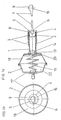
- Figure 1a shows a section of a coupling device according to the invention for a speed controller, which couples an actuator (2) shown here to an adjusting device, not shown, which is connected directly or indirectly to a throttle valve.
- Figure 1b shows a front view of the subject of the invention.
- the actuator (2) is designed here to reduce costs and to make the structure simple as a pneumatically actuated actuating element which is firmly connected to a vehicle body and consists of a base body (17) which is advantageously injection molded from plastic, one with the base body (17 ) firmly connected membrane (18), which on its side facing away from the base body (17) has an opening for receiving a plate-shaped component (20), in particular molded from plastic, which seals and seals the membrane (18).
- a spring (19) is arranged to specify a basic position of the actuator (2), which returns the actuator (2) to the basic position when the speed controller is switched off.
- the base body (17) also has an opening, not shown, via which the pressure chamber (22) of the actuator (2) is connected to a device for generating negative pressure, which is controlled by a control circuit of the speed controller.
- the actuator (2) can also be an electric drive.
- the component (20) On the side facing away from the base body (17), the component (20) has a resiliently designed latching part (14).
- the hollow cylindrical connecting piece (1) has, on its inside facing the actuator, a circumferential cross-sectional constriction (13) which latches with the latching part (14) of the component (20) .
- the dimensions of the locking device formed in this way are designed such that the membrane (18) is simultaneously pressed between the component (20) and the connecting piece (1) and the pressure chamber (22) is sealed from the atmosphere during the locking.
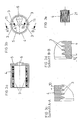
- the connecting piece (1) has, as in Figure 2a and Figure 2b shown, for easy and quick adjustment and quick attachment of a further component on its side facing away from the actuator (2), two sections on its outside facing away from each other, which have a number of radially extending sawtooth-like ribs (3) shown here by way of example, which extend parallel to one another in the axial direction over a predetermined range.
- the component that can be fastened to the connecting piece (1) is the adjusting piece (4), which is shown in FIGS. 3a and 3b and is also of hollow cylindrical design.
- the adjusting piece (4) has two opposing sections arranged on the inside of the adjusting piece (4) which, in order to obtain the largest possible adjustment range, have sawtooth-like ribs (3) arranged over the entire length of the inside, which run in the radial direction and extending in the axial direction are arranged parallel to each other.
- the distance between the ribs (3) of the connecting piece (1) corresponds essentially to the distance between the ribs (3) of the adjusting piece (4).
- the sections which are formed by the ribs (3) are arranged so that in one position of the adjusting piece (4) to the connecting piece (1) the adjusting piece (4) is freely displaceable in the axial direction over the connecting piece (1) , whereby a simple inexpensive and quick length adjustment of the coupling device according to the invention to a predetermined adjusting device is achieved in the idle position of a throttle valve.
- a radial takes place Relative rotation of the adjusting piece (4) to the connecting piece (1), whereby the ribs (3) interlock positively.
- the opposing ribs (3) on the adjusting piece (4) are offset in the axial direction by a predetermined amount (10), which here corresponds to approximately half the rib spacing, as shown in FIGS. 3c and Figure 3d show on an enlarged scale as section AA and BB.
- the ribs (3) of the connecting piece (1) pointing away from one another are also offset from one another in the axial direction by the amount (10), which corresponds to approximately half of the rib spacing, as can be seen from FIG. 4c and FIG. 4d. If such a fine adjustment is not required, the rib spacing can be increased with this arrangement, which simplifies production and reduces costs without the adjustment accuracy becoming too low.
- the ribs (3) of the adjusting piece (4) have an axial direction extending groove (11), which is shown in Figure 3b and the first ribs (3) of the connecting piece (1) have a bead (12) which is lower than the ribs (3) and their width substantially the width corresponds to the groove (11).
- the bead (12) engages in the groove (11) and thus secures the adjusting piece (4) against unwanted twisting.
- Figures 2a and 2b show the formation of the bead (12).
- FIGS. 2c and 2d each show the bead (12) in section on an enlarged scale.
- the bead (12) extends here, for example, over the first three to four ribs (3).
- the latching force can be adjusted by the number of ribs (3) over which the bead (12) extends.
- the cogging force is also due to the height of the Bead (12) can be preset, which can be lower, equal to or greater than the height of the ribs (3).
- the groove (11) can be arranged on the connecting piece (1) and the bead (12) on the adjusting piece (4).
- the ribs can also have several grooves (11) and beads (12).
- Figure 3e shows the adjusting piece (4) according to the invention on a reduced scale.
- the adjusting piece (4) has grooves on the entire circumference of the outer surface which extend in the axial direction and which simplify radial twisting.
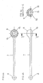
- the adjusting piece (4) has a cover (5) on its side facing away from the actuator (2).
- the cover (5) consists here, in order to enable simple and inexpensive production, together with the adjusting piece (4) in one piece.
- the cover (5) has an opening (6) for receiving the coupling rod (7), in one section of which the coupling rod (7) is slidably mounted.
- Figure 4a and Figure 4b show the coupling rod (7) in two different views.
- the coupling rod (7) has a thickening (8) on its end facing the actuator (2), which is formed in one piece.
- the thickening (8) is formed here, for example, by a ball head.
- the coupling rod (7) has a connection device (9) which can be connected to the adjusting device for simple and inexpensive installation.
- the connection device consists of a ball socket (15) which here has, for example, an elastic locking part (16) for receiving a ball head.
- the ball socket (15) can also have a plurality of locking parts (16).
- Figure 4c shows as section C-C according to Figure 4b, the ball socket (15) and the locking part (16).
- Figure 3b shows the formation of the opening (6) in the cover (5) of the adjusting piece (4) in which the coupling rod (7) is slidably mounted.
- the opening (6) has a first section, the diameter of which is larger than the diameter of the thickening (8) of the coupling rod (7) around the coupling rod (7) through the opening (6) of the cover (5) in the direction of the actuator (2) to be able to put through.
- the opening (6) has a second section, which has a taper that is smaller than the diameter of the coupling rod (7) and is designed as a locking element.
- the third section of the opening (6) is arranged in the center of the cover (5) of the adjusting piece (4) and slidably supports the engaging coupling rod (7).
- the actuator (2) of the speed controller is therefore always coupled to the adjusting device when the thickening (8) of the coupling rod (7) is non-positively connected to the opening (6) in the cover (5) of the adjusting piece (4).
- the preassembled actuator (2) which is firmly connected to the connecting piece (1), is attached to a part of the vehicle body or to the engine block.
- the coupling rod (7) is in the opening (6) of the cover (5) of the adjusting piece (4) snapped into place.
- the adjusting piece (4) is pushed over the connecting piece (1) and the coupling rod (7) is firmly connected to the adjusting device via the connecting device (9).
- the adjustment device is set to the idle position of the throttle valve spring-loaded.
- the adjusting piece is pushed axially over the connecting piece (1) until the thickening (8) of the coupling rod (7) is non-positively connected to the cover (5) of the adjusting piece (4).
- the coupling device can be adapted to the degree that is predetermined by the adjusting device and the tolerances of the adjusting device.
- the coupling rod (7) can be moved freely in the hollow cylindrical interior of the connecting piece (1) and the adjusting piece (4) when the accelerator pedal is actuated, without the actuator being subjected to any force.
- the pressure chamber (22) of the actuator (2) is subjected to negative pressure, which pulls the coupling rod (7) in the direction of the actuator (2).
- the coupling rod (7) is acted upon by the adjusting device with a force in the direction of the idle position of the throttle valve, so that the thickening (8) is non-positively connected to the adjusting piece (4) at all times.
- the actuator (2) returns to its basic position due to the force of the spring (19) and the driving speed can be determined in all areas by the accelerator pedal movement.
- connection device (9) can be articulated directly or indirectly on a throttle valve.
Landscapes
- Engineering & Computer Science (AREA)
- Chemical & Material Sciences (AREA)
- Combustion & Propulsion (AREA)
- Mechanical Engineering (AREA)
- Transportation (AREA)
- General Engineering & Computer Science (AREA)
- Control Of Throttle Valves Provided In The Intake System Or In The Exhaust System (AREA)
- Controls For Constant Speed Travelling (AREA)
Abstract
Description
- Die Erfindung betrifft eine Koppeleinrichtung für einen Geschwindigkeitsregler, insbesondere in Kraftfahrzeugen, mit relativ zueinander beweglichen Bauteilen, die kraftschlüssig miteinander koppelbar sind und die einen Stellantrieb des Geschwindigkeitsreglers mit einer Verstelleinrichtung verbinden, die direkt oder indirekt mit einer Drosselklappe verbunden ist.
- Eine Koppeleinrichtung dieser Art ist aus dem deutschen Gebrauchsmuster mit der Nummer GM 77 35 209 bekannt. Eine Koppeleinrichtung zwischen einer Verstelleinrichtung zum Verstellen des Betriebes einer Brennkraftmaschine und einem an eine Regelschaltung angeschlossenen Stellantrieb weist dabei zwei relativ zueinander verschiebbare Bauteile und eine an einem der beiden Bauteile angebrachte Rastvorrichtung auf. Die Rastvorrichtung verfügt über einen Riegel, der mittels eines Elektromagneten in eine an dem anderen der beiden Bauteile angebrachte Einrastmulde einrückbar ist. Das eine Bauteil ist dabei als ein Zylinder ausgelegt, der direkt an dem Gaspedalhebel angebracht sein kann. Das andere Bauteil ist als Kolben ausgebildet, der in dem Zylinder verschiebbar ist. Die Rastvorrichtung ist an der äußeren Umfangswand des Zylinders und die Einrastmulde ist an dem Kolben angeordnet. Der Kolben ist über eine Zahnstange mit dem Stellmotor verbunden. Ist der Geschwindigkeitsregler außer Betrieb, so ist die Verstelleinrichtung von dem Stellantrieb entkoppelt. Wird der Geschwindigkeitsregler eingeschaltet, wird der Riegel von dem Elektromagneten durch eine Öffnung in dem Zylinder auf die Kolbenfläche gedrückt. Der Stellantrieb fährt den Kolben aus der Leerlaufstellung solange dem Zylinder nach bis der Riegel in die Einrastmulde einrückt, was über einen Schalter ermittelt wird. Die Fahrgeschwindigkeit wird somit durch den Geschwindigkeitsregler regelbar. Wird der Geschwindigkeitsregler abgeschaltet, wird der Riegel durch eine Rückholfeder nach dem Abschalten des Elektromagneten aus der Einrastmulde zurückgezogen, wodurch die Fahrgeschwindigkeit wieder durch den Fahrer bestimmbar ist.
- Nachteilig erweist sich hierbei, daß der Aufbau durch die Verwendung eines Riegels, der durch einen Elektromagneten einrückbar ist und durch eine Feder rückholbar ist, nicht einfach und kostengünstig ist und daß zudem ein Schalter vorzusehen ist, der die Riegelstellung anzeigen muß.
- Weiterhin ist nachteilig, daß bei Einschalten des Geschwindigkeitsreglers der Riegel auf den Kolben drückt und der Stellantrieb den Kolben nachführen muß bis der Riegel in die Einrastmulde einrückt, was zu einer unerwünschten Verzögerung der Wirkung des Geschwindigkeitsreglers führen kann und den Verschleiß der Bauteile erhöht.
- Zudem ist nachteilig, daß der Fahrer bei einem erforderlichen Beschleunigungsvorgang erst den Widerstand des Riegels überwinden muß, damit eine Entkopplung der Bauteile erfolgt.
- Aus dem deutschen Gebrauchsmuster mit der Nummer GM 78 08 547 ist eine Koppeleinrichtung bekannt, die über ein pneumatisches Stellelement verfügt, dessen Stellbewegung auf eine Koppelstange übertragen wird. An der dem Stellelement abgewandten Seite der Koppelstange ist eine Anschlußeinrichtung über eine Justiereinrichtung mit der Koppelstange verbindbar. Die Anschlußvorrichtung ist hier als Kugelpfanne ausgebildet.
- Nachteilig erweist sich hierbei, daß eine Entkopplung zwischen dem Stellelement und einer an die Anschlußeinrichtung angeschlossene Verstelleinrichtung nicht vorgesehen ist, so daß das Stellelement bei jeder Bewegung der Verstelleinrichtung mit Kraft beaufschlagt wird, wodurch der Kraftaufwand zum Betätigen der Verstelleinrichtung erhöht und der Verschleiß des Verstellelements heraufgesetzt wird. Weiterhin erweist sich als nachteilig, daß die Justiereinrichtung durch ein Gewinde und eine Überwurfmutter aufgebaut ist, wodurch eine feinfühlige genaue und schnelle Justage der Koppeleinrichtung an eine Grundstellung der Verstelleinrichtung nur schwer möglich ist, da durch das Anziehen der Mutter Kraft in die Verstellrichtung erzeugt wird.
- Der Erfindung liegt die Aufgabe zugrunde, eine Koppeleinrichtung zu schaffen, die einfach und kostengünstig herstellbar und montierbar ist, die einfach und schnell an eine vorgegebene Verstelleinrichtung anpaßbar ist und die den Stellantrieb ohne zusätzlichen Kraftaufwand von der Verstelleinrichtung entkoppelt, wenn die Verstelleinrichtung manuell betätigt wird.
- Die Aufgabe wird erfindungsgemäß dadurch gelöst, daß ein hohlzylinderförmiger Anschlußstutzen fest mit dem Stellantrieb verbunden ist, daß der Anschlußstutzen auf der dem Stellantrieb abgewandten Seite über eine Justiereinrichtung mit einem hohlzylinderförmigen Justierstück verbunden ist, daß das Justierstück auf der dem Stellantrieb abgewandten Seite einen Deckel mit einem Druchbruch aufweist, in dessen einem Abschnitt eine Koppelstange gleitend gelagert ist, daß die Koppelstange an ihrer dem Stellantrieb zugewandten Seite eine Verdickung aufweist, die größer ist als der Abschnitt des Durchbruchs, in dem die Koppelstange gelagert ist und daß die Koppelstange an ihrer dem Stellantrieb abgewandten Seite eine Anschlußeinrichtung aufweist, die die Koppelstange mit der Verstelleinrichtung verbindet.
- Vorteilhaft ist es, daß ein hohlzylinderförmiger Anschlußstutzen fest mit dem Stellantrieb verbunden ist, weil somit die Stellbewegung des Stellantriebs sicher auf ein Bauteil der Koppeleinrichtung übertragen wird, in dem durch eine hohlzylinderförmige Ausbildung ein weiteres Bauteil der Koppeleinrichtung frei verschieblich ist.
- Weiterhin erweist sich als vorteilhaft, daß der Anschlußstutzen auf der dem Stellantrieb abgewandten Seite über eine Justiereinrichtung mit einem hohlzylinderförmigen Justierstück verbunden ist, weil somit die Gesamtlänge der Koppeleinrichtung einfach, kostengünstig und schnell kraftschlüssig an das Maß anpaßbar ist, daß durch die Verstelleinrichtung und den Stellantrieb vorgegeben ist und durch die Toleranzen der Verstelleinrichtung bestimmt ist. Das Maß ist dabei maßgeblich durch die Leerlaufstellung einer Drosselklappe, die mit der Verstelleinrichtung verbunden ist, vorgegeben.
- Dadurch, daß das Justierstück auf der dem Stellantrieb abgewandten Seite einen Deckel mit einem Druchbruch aufweist, in dessen einem Abschnitt eine Koppelstange gleitend gelagert ist, ergibt sich der Vorteil, daß die Koppelstange frei in dem hohlzylinderförmigen Innenraum des Anschlußstutzens und des Justierstücks verschiebbar ist, wodurch auf einfache und kostengünstige Weise, eine Entkopplung zwischen Stellantrieb und Verstelleinrichtung erreicht wird und Platz eingespart wird.
- In diesem Zusammenhang ist es vorteilhaft, daß die Koppelstange an ihrer dem Stellantrieb zugewandten Seite eine Verdickung aufweist, die größer ist, als der Abschnitt des Durchbruchs, in dem die Koppelstange gelagert ist, weil somit die Koppelstange auf eine einfache und kostengünstige Weise an den Stellantrieb in eine kraftwirkende Richtung angkoppelbar ist, wenn der Geschwindigkeitsregler in Betrieb gesetzt wird, da in der Leerlaufstellung der Verstelleinrichtung die Justiereinrichtung so justiert ist, daß die Verdickung der Koppelstange kraftschlüssig mit dem Durchbruch des Deckels verbunden ist. Gleichzeitig ist es jederzeit möglich, das Kraftfahrzeug bei eingeschaltetem Geschwindigkeitsregler manuell zu beschleunigen, da die Koppelstange in Richtung auf den Stellantrieb ohne zusätzlichen Kraftaufwand entkoppelbar ist und frei beweglich bleibt.
- Vorteilhaft ist es, daß die Koppelstange an ihrer dem Stellantrieb abgewandten Seite eine Anschlußeinrichtung aufweist, die die Koppelstange mit der Verstelleinrichtung verbindet, wodurch eine einfache und kostengünstige Montage der Koppeleinrichtung erreicht wird.
- Weitere vorteilhafte Ausgestaltungen und Weiterbildungen des Erfindungsgegenstands ergeben sich aus den Unteransprüchen.
- Insbesondere ist es vorteilhaft, daß die Justiereinrichtung durch sich gegenüberliegende Abschnitte auf der Innenseite und durch voneinander weg weisende Abschnitte auf der Außenseite des Anschlußstutzens und des Justierstücks gebildet wird, daß die Abschnitte radial verlaufende sägezahnartig ausgebildete Rippen aufweisen, die sich über einen vorgegebenen Bereich parallel zueinander in axialer Richtung erstrecken, daß die Abschnitte derart angeordnet sind, daß das Justierstück zu dem Anschlußstutzen frei in axialer Richtung verschiebbar ist und daß durch eine radiale Relativdrehung zwischen dem Justierstück und dem Anschlußstutzen die Rippen der Abschnitte formschlüssig ineinandergreifen, weil somit auf einfache und kostengünstige Weise die Koppeleinrichtung formschlüssig ohne zusätzlichen Kraftaufwand in axialer Richtung auf das durch die Verstelleinrichtung in Leerlaufstellung vorgegebene Maß einstellbar ist.
- In diesem Zusammenhang ist es weiterhin vorteilhaft, daß die sich jeweils gegenüberliegenden und voneinander weg weisenden Rippen, sowohl bei dem Anschlußstutzen als auch bei dem Justierstück, in axialer Richtung um einen vorgegebenen Betrag der insbesondere dem halben Rippenabstand entspricht, zueinander versetzt angeordnet sind, weil auf diese Weise eine feinere genauere Justage erreicht wird, die insbesondere den kleinsteinstellbaren Abstand halbiert oder aber bei einem leicht fertigbaren größeren Abstand der Rippen, wodurch die Herstellungskosten herabgesetzt werden, eine feinere oder gleichgenaue Justage möglich ist.
- Dadurch, daß die Rippen des Justierstücks oder des Anschlußstutzens mindestens eine in axialer Richtung durchlaufende Nut aufweisen, daß die Rippen des Justierstücks oder des Anschlußstutzens mindestens eine sich über einige der ersten Rippen in axialer Richtung erstreckende Wulst aufweisen und daß die Breite der Wulst der Breite der Nut im wesentlichen entspricht, ergibt sich der Vorteil, daß auf einfache und kostengünstige Weise eine Festsetzung des Justierstücks zu dem Anschlußstutzen erreicht wird, die ein ungewolltes Verdrehen und Entkoppeln verhindert, wodurch die Sicherheit bei dem Betrieb des Geschwindigkeitsreglers erhöht wird.
- Dadurch, daß die Koppelstange das Justierstück und der Anschlußstutzen aus Kunststoff gespritzt sind, ergibt sich der Vorteil, daß die Herstellung dieser Bauteile einfach und kostengünstig ist.
- Ein Ausführungsbeispiel des Erfindungsgegenstands ist in den Zeichnungen in unterschiedlichen Maßstäben dargestellt und wird im folgenden näher beschrieben.
- Gleiche oder gleichwirkende Bauteile werden in den Zeichnungen mit gleichen Bezugszeichen versehen.
- Es zeigen
- Figur 1a eine erfindungsgemäße Koppeleinrichtung mit einem Stellantrieb als Schnitt,
- Figur 1b eine erfindungsgemäße Koppeleinrichtung in einer Vorderansicht,
- Figur 2a einen Anschlußstutzen der erfindungsgemäßen Koppeleinrichtung als Schnitt,
- Figur 2b einen Anschlußstutzen in Vorderansicht,
- Figur 2c eine Einzelheit Y, entsprechend Figur 2a,
- Figur 2d eine Einzelheit Z, entsprechend Figur 2a,
- Figur 2e eine Einzelheit X,entsprechend Figur 2b,
- Figur 3a ein Justierstück der erfindungsgemäßen Koppeleinrichtung als Schnitt,
- Figur 3b ein Justierstück in Vorderansicht,
- Figur 3c einen Schnitt A-A entsprechend Figur 3b,
- Figur 3d einen Schnitt B-B entsprechend Figur 3b,
- Figur 3e eine Seitenansicht des erfindungsgemäßen Justierstücks,
- Figur 4a eine Koppelstange des Erfindungsgegenstands in Unteransicht,
- Figur 4b eine Koppelstange in einer Seitenansicht,
- Figur 4c einen Schnitt C-C entsprechend Figur 4b.
- Figur 1a zeigt als Schnitt eine erfindungsgemäße Koppeleinrichtung für einen Geschwindigkeitsregler, die einen hier mit dargestellten Stellantrieb (2) an eine nicht dargestellte Verstelleinrichtung ankoppelt, die direkt oder indirekt mit einer Drosselklappe verbunden ist. Figur 1b zeigt eine Vorderansicht des Erfindungsgegenstands.
- Der Stellantrieb (2) ist hier um Kosten zu senken und den Aufbau einfach zu gestalten als pneumatisch betätigbares Stellelement ausgebildet, das fest mit einer Fahrzeugkarosserie verbunden ist und aus einem Grundkörper (17) der vorteilhaft aus Kunststoff gespritzt ist, einer mit dem Grundkörper (17) fest verbundenen Membrane (18), die an ihrer dem Grundkörper (17) abgewandten Seite eine öffnung zur Aufnahme eines, insbesondere aus Kunststoff gespritzten, tellerförmigen Bauteils (20) aufweist, das die Membrane (18) abschließt und abdichtet. Zwischen dem Grundkörper (17) und dem Bauteil (20) ist zur Vorgabe einer Grundstellung des Stellantriebs (2) eine Feder (19) angeordnet, die bei Abschalten des Geschwindigkeitsreglers den Stellantrieb (2) in die Grundstellung zurückstellt. Der Grundkörper (17) weist zudem eine nicht dargestellte Öffnung auf, über die die Druckkammer (22) des Stellantriebs (2) mit einer Einrichtung zur Erzeugung von Unterdruck verbunden ist, die von einer Regelschaltung des Geschwindigkeitsreglers angesteuert wird.
- In einem anderen Ausführungsbeispiel kann der Stellantrieb (2) auch ein elektrischer Antrieb sein.
- Auf der dem Grundkörper (17) abgewandten Seite weist das Bauteil (20) ein federnd ausgelegtes Rastteil (14) auf.
- Der hohlzylinderförmige Anschlußstutzen (1) weist, wie in Figur 2a gezeigt, um die Montage zu vereinfachen, an seiner dem Stellantrieb zugewandten Seite an seiner Innenseite eine umlaufende Querschnittsverengung (13) auf, die mit dem Rastteil (14) des Bauteils (20) verrastet. Die Bemaßung der so gebildeten Rasteinrichtung ist derart ausgelegt, daß bei der Verrastung gleichzeitig die Membrane (18) zwischen dem Bauteil (20) und dem Anschlußstutzen (1) festgedrückt und die Druckkammer (22) gegen die Atmosphäre abgedichtet wird. Der Anschlußstutzen (1) weist, wie in Figur 2a und Figur 2b gezeigt, zur einfachen und schnellen Justage und schnellen Befestigung eines weiteren Bauteils auf seiner dem Stellantrieb (2) abgewandten Seite zwei an seiner Außenseite angeordnete voneinander weg weisende Abschnitte auf, die eine hier beispielhaft eingezeichnete Anzahl radial verlaufende sägezahnartig ausgebildetete Rippen (3) aufweisen, die sich über einen vorgegebenen Bereich parallel zueinander angeordnet in axialer Richtung erstrecken. Das an dem Anschlußstutzen (1) befestigbare Bauteil ist das Justierstück (4), welches in den Figuren 3a und 3b dargestellt ist und ebenfalls hohlzylinderförmig ausgebildet ist. Das Justierstück (4) verfügt über zwei sich gegenüberliegende auf der Innenseite des Justierstücks (4) angeordnete Abschnitte, die, um einen möglichst großen Verstellbereich zu erhalten, über die gesamte Länge der Innenseite angeordnete sägezahnartige Rippen (3) aufweisen, die in radialer Richtung verlaufen und sich in axialer Richtung erstreckend parallel zueinander angeordnet sind.
- Der Abstand der Rippen (3) des Anschlußstutzens (1) stimmt im wesentlichen mit dem Abstand der Rippen (3) des Justierstücks (4) überein.
- Die Abschnitte, die durch die Rippen (3) gebildet werden, sind dabei so angeordnet, daß in einer Stellung des Justierstücks (4) zu dem Anschlußstutzen (1) das Justierstück (4) frei in axialer Richtung über den Anschlußstutzen (1) verschiebbar ist, wodurch eine einfache kostengünstige und schnelle Längenanpassung der erfindungsgemäßen Koppeleinrichtung an eine vorgegebene Verstelleinrichtung in der Leerlaufstellung einer Drosselklappe erreicht wird.
- Um eine axiale Festsetzung des Justierstücks (4) zu dem Anschlußstutzen (1) zu erreichen, bei der in der Leerlaufstellung der Drosselklappe die Verstelleinrichtung kraftschlüssig über die Koppeleinrichtung mit dem Stellantrieb (2) verbunden ist, erfolgt eine radiale Relativdrehung des Justierstücks (4) zu dem Anschlußstutzen (1), wodurch die Rippen (3) formschlüssig ineinandergreifen. Um eine engere feinere Justierung zu erreichen, sind die sich gegenüberliegenden Rippen (3) an dem Justierstück (4) in axialer Richtung um einen vorgegebenen Betrag (10), der hier etwa der Hälfte des Rippenabstands entspricht, zueinander versetzt angeordnet, wie Figur 3c und Figur 3d in vergrößertem Maßstab als Schnitt A-A und B-B zeigen. Auch die voneinander weg weisenden Rippen (3) des Anschlußstutzens (1) sind wie aus Figur 4c und Figur 4d zu entnehmen ist, um den Betrag (10), der etwa der Hälfte des Rippenabstands entspricht, zueinander in axialer Richtung versetzt angeordnet. Ist eine derart feine Justierung nicht erforderlich, kann mit dieser Anordnung der Rippenabstand vergrößert werden, was die Fertigung vereinfacht und die Kosten herabsetzt, ohne daß die Justagegenauigkeit zu gering wird.
- Um die Justiereinrichtung festzusetzen, und gegen ein unbeabsichtigtes Verdrehen zu sichern, wodurch die Rippen (3) des Justierstücks (4) und des Anschlußstutzens (1) außer Formschluß geraten können, weisen die Rippen (3) des Justierstücks (4) eine in axialer Richtung verlaufende Nut (11) auf, die in Figur 3b dargestellt ist und weisen die ersten Rippen (3) des Anschlußstutzens (1) eine Wulst (12) auf, die niedriger ist, als die Rippen (3) und deren Breite im wesentlichen der Breite der Nut (11) entspricht. Die Wulst (12) verrastet in der Nut (11) und sichert somit das Justierstück (4) gegen ein ungewolltes Verdrehen. Die Ausbildung der Wulst (12) zeigen die Figuren 2a und 2b. Die Einzelheit X in Figur 2e zeigt die Wulst (12) in einer Vorderansicht in vergrößertem Maßstab. Die Einzelheit Y und die Einzelheit Z in den Figuren 2c und 2d zeigen die Wulst (12) jeweils im Schnitt in vergrößertem Maßstab. Die Wulst (12) erstreckt sich hier beispielhaft über die ersten drei bis vier Rippen (3). Durch die Anzahl der Rippen (3) über die sich die Wulst (12) erstreckt, ist die Rastkraft einstellbar. Die Rastkraft ist zudem durch die Höhe der Wulst (12) voreinstellbar, die niedriger, gleich oder größer als die Höhe der Rippen (3) sein kann.
- In einer anderen Ausführungsform kann die Nut (11) auf dem Anschlußstutzen (1) und die Wulst (12) auf dem Justierstück (4) angeordnet sein. Die Rippen können auch über mehrere Nuten (11) und Wülste (12) verfügen.
- Figur 3e zeigt das erfindungsgemäße Justierstück (4) in verkleinertem Maßstab. Das Justierstück (4) weist hier um das Justieren zu vereinfachen, auf dem gesamten Umfang der Außenfläche sich in axialer Richtung erstreckende Rillen auf, die ein radiales Verdrehen vereinfachen.
- Wie aus Figur 1a und Figur 3a erkennbar ist, weist das Justierstück (4) an seiner dem Stellantrieb (2) abgewandten Seite einen Deckel (5) auf. Der Deckel (5) besteht hier, um eine einfache und kostengünstige Herstellung zu ermöglichen, zusammen mit dem Justierstück (4) aus einem Stück.
- Der Deckel (5) weist zur Aufnahme der Koppelstange (7) einen Durchbruch (6) auf, in dessen einem Abschnitt die Koppelstange (7) gleitend gelagert ist.
- Figur 4a und Figur 4b zeigen die Koppelstange (7) in zwei unterschiedlichen Ansichten.
- Die Koppelstange (7) weist an ihrem dem Stellantrieb (2) zugewandtem Ende eine Verdickung (8) auf, die einstückig angeformt ist. Die Verdickung (8) wird hier beispielhaft durch einen Kugelkopf gebildet. An der dem Stellantrieb (2) abgewandten Seite weist die Koppelstange (7) eine Anschlußeinrichtung (9) auf, die für eine einfache und kostengünstige Montage mit der Verstelleinrichtung verbindbar ist. Die Anschlußeinrichtung besteht für eine einfache Montage aus einer Kugelpfanne (15), die hier beispielhaft ein elastisches Rastteil (16) zur Aufnahme eines Kugelkopfes aufweist. In einem anderen Ausführungsbeispiel kann die Kugelpfanne (15) auch mehrere Rastteile (16) aufweisen.
- Figur 4c zeigt als Schnitt C-C entsprechend Figur 4b die Kugelpfanne (15) und das Rastteil (16).
- Figur 3b zeigt die Ausbildung des Durchbruchs (6) in dem Deckel (5) des Justierstücks (4), in dem die Koppelstange (7) gleitend gelagert ist.
- Der Durchbruch (6) verfügt über einen ersten Abschnitt, dessen Durchmesser größer ist, als der Durchmesser der Verdickung (8) der Koppelstange (7) um die Koppelstange (7) durch den Durchbruch (6) des Deckels (5) in Richtung des Stellantriebs (2) hindurchstecken zu können.
- Der Durchbruch (6) weist einen zweiten Abschnitt auf, der eine Verjüngung aufweist, die kleiner ist, als der Durchmesser der Koppelstange (7) und als Rastelement ausgebildet ist. Der dritte Abschnitt des Durchbruchs (6) ist in dem Deckel (5) des Justierstücks (4) mittig angeordnet und nimmt die eingerastete Koppelstange (7) gleitend lagernd auf.
- Der Stellantrieb (2) des Geschwindigkeitsreglers ist somit immer dann an die Verstelleinrichtung angekoppelt, wenn die Verdickung (8) der Koppelstange (7) kraftschlüssig mit dem Durchbruch (6) in dem Deckel (5) des Justierstücks (4) verbunden ist.
- Im folgendem wird die Funktion der erfindungsgemäßen Koppeleinrichtung kurz beschrieben.
- Bei der Montage der Koppeleinrichtung wird der vormontierte Stellantrieb (2), der fest mit dem Anschlußstutzen (1) verbunden ist, an einem Teil der Fahrzeugkarosserie oder an dem Motorblock angebracht. Die Koppelstange (7) wird in dem Durchbruch (6) des Deckels (5) des Justierstücks (4) eingerastet. Dann wird das Justierstück (4) über den Anschlußstutzen (1) geschoben und die Koppelstange (7) über die Anschlußeinrichtung (9) mit der Verstelleinrichtung fest verbunden. Die Verstelleinrichtung ist auf die Leerlaufstellung der Drosselklappe federbelastet eingestellt. Zur Justierung der erfindungsgemäßen Koppeleinrichtung an die Verstelleinrichtung wird das Justierstück soweit axial über den Anschlußstutzen (1) geschoben bis die Verdickung (8) der Koppelstange (7) kraftschlüssig mit dem Deckel (5) des Justierstücks (4) verbunden ist. Dann wird das Justierstück (4) radial zu dem Anschlußstutzen (1) verdreht, so daß die Rippen (3) formschlüssig ineinandergreifen und die Wulst (12) in die Nut (11) einrastet. Auf diese einfache Weise ist die Koppeleinrichtung an das Maß anpaßbar, das durch die Verstelleinrichtung und die Toleranzen der Verstelleinrichtung vorgegeben ist.
- Ist der Geschwindigkeitsregler außer Betrieb, so ist bei einer Betätigung des Gaspedalhebels die Koppelstange (7) frei in dem hohlzylinderförmigen Innenraum des Anschlußstutzens (1) und des Justierstücks (4) verschiebbar, ohne daß der Stellantrieb mit Kraft beaufschlagt wird.
- Wird der Geschwindigkeitsregler eingeschaltet, wird je nach zu regelnder Fahrgeschwindigkeit die Druckkammer (22) des Stellantriebs (2) mit Unterdruck beaufschlagt, der die Koppelstange (7) in Richtung Stellantrieb (2) zieht. Die Koppelstange (7) wird dabei von der Verstelleinrichtung durch eine Feder mit Kraft in Richtung Leerlaufstellung der Drosselklappe beaufschlagt, so daß die Verdickung (8) jederzeit mit dem Justierstück (4) kraftschlüssig in Verbindung steht.
- Erfordert z. B. eine Notsituation, daß das Fahrzeug beschleunigt werden muß, so ist die Koppelstange (7) frei in dem Durchbruch (6) verschiebbar, ohne daß der Stellantrieb (2) mit Kraft beaufschlagt wird.
- Wird der Geschwindigkeitsregler abgeschaltet, so nimmt der Stellantrieb (2) bedingt durch die wirkende Kraft der Feder (19) wieder seine Grundstellung ein und die Fahrgeschwindigkeit kann in allen Bereichen durch die Gaspedalbewegung bestimmt werden.
- Um eine einfache und kostengünstige Herstellung der Koppelstange (7), des Justierstücks (4) und des Anschlußstutzens (1) zu erreichen, werden diese Bauteile aus Kunststoff gespritzt. Diese Bauteile können aber auch aus anderen Materialien bestehen, wie z. B. Metall. Die Anschlußeinrichtung (9) kann in einem anderen Ausführungsbeispiel direkt oder indirekt an einer Drosselklappe angelenkt sein.
Claims (15)
Applications Claiming Priority (2)
| Application Number | Priority Date | Filing Date | Title |
|---|---|---|---|
| DE3818310 | 1988-05-30 | ||
| DE3818310A DE3818310C1 (de) | 1988-05-30 | 1988-05-30 |
Publications (2)
| Publication Number | Publication Date |
|---|---|
| EP0344432A1 true EP0344432A1 (de) | 1989-12-06 |
| EP0344432B1 EP0344432B1 (de) | 1991-12-27 |
Family
ID=6355416
Family Applications (1)
| Application Number | Title | Priority Date | Filing Date |
|---|---|---|---|
| EP89106248A Expired - Lifetime EP0344432B1 (de) | 1988-05-30 | 1989-04-08 | Koppeleinrichtung für einen Geschwindigkeitsregler |
Country Status (5)
| Country | Link |
|---|---|
| US (1) | US4928646A (de) |
| EP (1) | EP0344432B1 (de) |
| AU (1) | AU617472B2 (de) |
| DE (1) | DE3818310C1 (de) |
| ES (1) | ES2029091T3 (de) |
Citations (4)
| Publication number | Priority date | Publication date | Assignee | Title |
|---|---|---|---|---|
| US3556245A (en) * | 1968-12-04 | 1971-01-19 | Ford Motor Co | Position to voltage transducer and speed control system utilizing same |
| DE2512138A1 (de) * | 1975-03-20 | 1976-10-07 | Teves Gmbh Alfred | Vorrichtung zur geschwindigkeitsregelung |
| DE7735209U1 (de) * | 1977-11-17 | 1978-05-03 | Audi Nsu Auto Union Ag, 7107 Neckarsulm | Fahrgeschwindigkeitsregelvorrichtung fuer kraftfahrzeuge |
| US4715738A (en) * | 1986-12-22 | 1987-12-29 | Ford Motor Company | Carburetor throttle lever/speed control connector |
Family Cites Families (11)
| Publication number | Priority date | Publication date | Assignee | Title |
|---|---|---|---|---|
| US3077239A (en) * | 1960-05-27 | 1963-02-12 | Edward F Simas | Automobile speed control device |
| US3157244A (en) * | 1962-07-23 | 1964-11-17 | Gen Motors Corp | Vehicle speed warning and cruise control system with preengagement inhibiting means |
| DE7808547U1 (de) * | 1978-03-21 | 1979-08-30 | Robert Bosch Gmbh, 7000 Stuttgart | Pneumatisches Stellorgan |
| US4220218A (en) * | 1979-02-09 | 1980-09-02 | General Motors Corporation | Vehicle road speed control system with flow amplifier |
| CA1081561A (en) * | 1979-03-05 | 1980-07-15 | Paul H. Boche | Cruise control device for vehicles |
| JPS6039859B2 (ja) * | 1979-07-19 | 1985-09-07 | トヨタ自動車株式会社 | アクセルペダル制御装置 |
| US4407385A (en) * | 1980-11-04 | 1983-10-04 | Return On Investment Corporation | Cruise control modulator |
| DE3201071C2 (de) * | 1982-01-13 | 1984-11-08 | Deutsche Vergaser Gesellschaft GmbH & Co KG, 1000 Berlin | Steuergerät für die Drosselklappe eines Klappenstutzens oder Vergasers |
| DE3326460A1 (de) * | 1983-07-22 | 1985-02-07 | Westfälische Metall Industrie KG Hueck & Co, 4780 Lippstadt | Vorrichtung zum einstellen der fahrgeschwindigkeit eines kraftfahrzeugs |
| US4798258A (en) * | 1984-04-24 | 1989-01-17 | Dana Corporation | Throttle control assembly for a vehicle speed control unit |
| DE3608791A1 (de) * | 1986-03-15 | 1987-09-17 | Teves Gmbh Alfred | Vorrichtung zur steuerung der antriebsleistung eines fahrzeugmotors fuer kraftfahrzeuge mit vortriebsregelung |
-
1988
- 1988-05-30 DE DE3818310A patent/DE3818310C1/de not_active Expired
-
1989
- 1989-04-08 ES ES198989106248T patent/ES2029091T3/es not_active Expired - Lifetime
- 1989-04-08 EP EP89106248A patent/EP0344432B1/de not_active Expired - Lifetime
- 1989-05-17 AU AU34883/89A patent/AU617472B2/en not_active Ceased
- 1989-05-30 US US07/358,264 patent/US4928646A/en not_active Expired - Fee Related
Patent Citations (4)
| Publication number | Priority date | Publication date | Assignee | Title |
|---|---|---|---|---|
| US3556245A (en) * | 1968-12-04 | 1971-01-19 | Ford Motor Co | Position to voltage transducer and speed control system utilizing same |
| DE2512138A1 (de) * | 1975-03-20 | 1976-10-07 | Teves Gmbh Alfred | Vorrichtung zur geschwindigkeitsregelung |
| DE7735209U1 (de) * | 1977-11-17 | 1978-05-03 | Audi Nsu Auto Union Ag, 7107 Neckarsulm | Fahrgeschwindigkeitsregelvorrichtung fuer kraftfahrzeuge |
| US4715738A (en) * | 1986-12-22 | 1987-12-29 | Ford Motor Company | Carburetor throttle lever/speed control connector |
Also Published As
| Publication number | Publication date |
|---|---|
| AU3488389A (en) | 1989-11-30 |
| US4928646A (en) | 1990-05-29 |
| AU617472B2 (en) | 1991-11-28 |
| EP0344432B1 (de) | 1991-12-27 |
| DE3818310C1 (de) | 1989-11-30 |
| ES2029091T3 (es) | 1992-07-16 |
Similar Documents
| Publication | Publication Date | Title |
|---|---|---|
| DE69014645T2 (de) | Gaspedal für ein elektronisches drosselbetätigungssystem. | |
| DE69103336T2 (de) | Steuereinrichtung der Lichtstrahlrichtung eines Fahrzeugscheinwerfers. | |
| EP0659606A1 (de) | Gaspedaleinrichtung für ein Kraftfahrzeug | |
| DE102005012380B4 (de) | Nicht abgedichtete Parkstellgliedführung für Hybridgetriebe | |
| EP0787617A2 (de) | Fahrpedaleinheit für Fahrzeuge | |
| DE3307887C2 (de) | Anordnung zur Befestigung eines Bremskraftverstärkers | |
| DE10213249B4 (de) | Betätigungsmechanismus für Feststellbremsen | |
| EP0402521A1 (de) | Lastverstelleinrichtung | |
| EP1101021B1 (de) | Kanalsystem, insbesondere saugrohr für eine brennkraftmaschine | |
| DE68903236T2 (de) | Verbindungselement zwischen einem bedienungspedal und einen translatorisch bewegten steuerglied. | |
| EP0344432B1 (de) | Koppeleinrichtung für einen Geschwindigkeitsregler | |
| DE102006041562B4 (de) | Stellvorrichtung für eine Verbrennungskraftmaschine | |
| DE19505374C2 (de) | Vorrichtung für die Einstellung des Verstellweges eines Gaspedales | |
| DE102010062785A1 (de) | Elektromechanischer Bremskraftverstärker mit einstellbarer nicht-linearer Unterstützungskraft | |
| DE19510528A1 (de) | Verstelleinrichtung | |
| EP1233321A2 (de) | Pedal | |
| DE19702251C2 (de) | Zentralverriegelungsstellelement für Türen oder Klappen von Kraftfahrzeugen | |
| DE10062988A1 (de) | Hydraulische Betätigungseinrichtung an Kraftfahrzeugen | |
| DE3726548C2 (de) | ||
| WO2005051721A1 (de) | Befestigungs-system zur befestigung eines bauteils an einem träger-element | |
| DE69503740T2 (de) | Vorrichtung zum erkennen der überbeschleunigung in kraftfahrzeugmotoren | |
| EP0795185B1 (de) | Drehschalter, insbesondere getriebeschalter für kraftfahrzeuge | |
| DE3136020A1 (de) | Abdeckkappe fuer durch druckknopfbetaetigung ein- und ausschaltbare steuer- oder schaltvorrichtungen | |
| EP0648626B1 (de) | Kopplungseinrichtung für eine Klappenanordnung | |
| DE9206249U1 (de) | Betätigungszug |
Legal Events
| Date | Code | Title | Description |
|---|---|---|---|
| PUAI | Public reference made under article 153(3) epc to a published international application that has entered the european phase |
Free format text: ORIGINAL CODE: 0009012 |
|
| AK | Designated contracting states |
Kind code of ref document: A1 Designated state(s): ES FR GB IT SE |
|
| 17P | Request for examination filed |
Effective date: 19900417 |
|
| 17Q | First examination report despatched |
Effective date: 19910319 |
|
| ITF | It: translation for a ep patent filed | ||
| GRAA | (expected) grant |
Free format text: ORIGINAL CODE: 0009210 |
|
| AK | Designated contracting states |
Kind code of ref document: B1 Designated state(s): ES FR GB IT SE |
|
| ET | Fr: translation filed | ||
| GBT | Gb: translation of ep patent filed (gb section 77(6)(a)/1977) | ||
| REG | Reference to a national code |
Ref country code: ES Ref legal event code: FG2A Ref document number: 2029091 Country of ref document: ES Kind code of ref document: T3 |
|
| PLBE | No opposition filed within time limit |
Free format text: ORIGINAL CODE: 0009261 |
|
| STAA | Information on the status of an ep patent application or granted ep patent |
Free format text: STATUS: NO OPPOSITION FILED WITHIN TIME LIMIT |
|
| 26N | No opposition filed | ||
| PGFP | Annual fee paid to national office [announced via postgrant information from national office to epo] |
Ref country code: SE Payment date: 19930415 Year of fee payment: 5 |
|
| PG25 | Lapsed in a contracting state [announced via postgrant information from national office to epo] |
Ref country code: SE Effective date: 19940409 |
|
| EUG | Se: european patent has lapsed |
Ref document number: 89106248.1 Effective date: 19941110 |
|
| PGFP | Annual fee paid to national office [announced via postgrant information from national office to epo] |
Ref country code: GB Payment date: 20000323 Year of fee payment: 12 |
|
| PGFP | Annual fee paid to national office [announced via postgrant information from national office to epo] |
Ref country code: ES Payment date: 20000405 Year of fee payment: 12 |
|
| PGFP | Annual fee paid to national office [announced via postgrant information from national office to epo] |
Ref country code: FR Payment date: 20000417 Year of fee payment: 12 |
|
| PG25 | Lapsed in a contracting state [announced via postgrant information from national office to epo] |
Ref country code: GB Free format text: LAPSE BECAUSE OF NON-PAYMENT OF DUE FEES Effective date: 20010408 |
|
| PG25 | Lapsed in a contracting state [announced via postgrant information from national office to epo] |
Ref country code: ES Free format text: LAPSE BECAUSE OF NON-PAYMENT OF DUE FEES Effective date: 20010409 |
|
| PG25 | Lapsed in a contracting state [announced via postgrant information from national office to epo] |
Ref country code: FR Free format text: THE PATENT HAS BEEN ANNULLED BY A DECISION OF A NATIONAL AUTHORITY Effective date: 20010430 |
|
| GBPC | Gb: european patent ceased through non-payment of renewal fee |
Effective date: 20010408 |
|
| REG | Reference to a national code |
Ref country code: FR Ref legal event code: ST |
|
| REG | Reference to a national code |
Ref country code: ES Ref legal event code: FD2A Effective date: 20030203 |
|
| PG25 | Lapsed in a contracting state [announced via postgrant information from national office to epo] |
Ref country code: IT Free format text: LAPSE BECAUSE OF NON-PAYMENT OF DUE FEES;WARNING: LAPSES OF ITALIAN PATENTS WITH EFFECTIVE DATE BEFORE 2007 MAY HAVE OCCURRED AT ANY TIME BEFORE 2007. THE CORRECT EFFECTIVE DATE MAY BE DIFFERENT FROM THE ONE RECORDED. Effective date: 20050408 |