EP0344142B1 - Verfahren zum kombinierten Schneiden und Nachbearbeiten von Glaswaren oder Kristallwaren mittels abrasiver Werkzeuge und Vorrichtung zur Durchführung des Verfahrens - Google Patents
Verfahren zum kombinierten Schneiden und Nachbearbeiten von Glaswaren oder Kristallwaren mittels abrasiver Werkzeuge und Vorrichtung zur Durchführung des Verfahrens Download PDFInfo
- Publication number
- EP0344142B1 EP0344142B1 EP89870069A EP89870069A EP0344142B1 EP 0344142 B1 EP0344142 B1 EP 0344142B1 EP 89870069 A EP89870069 A EP 89870069A EP 89870069 A EP89870069 A EP 89870069A EP 0344142 B1 EP0344142 B1 EP 0344142B1
- Authority
- EP
- European Patent Office
- Prior art keywords
- article
- cutting
- abrasive
- dressing
- tool
- Prior art date
- Legal status (The legal status is an assumption and is not a legal conclusion. Google has not performed a legal analysis and makes no representation as to the accuracy of the status listed.)
- Expired - Lifetime
Links
- 238000005520 cutting process Methods 0.000 title claims abstract description 71
- 238000000034 method Methods 0.000 title abstract description 8
- 239000011521 glass Substances 0.000 claims abstract description 26
- 239000013078 crystal Substances 0.000 claims abstract description 22
- 230000007246 mechanism Effects 0.000 claims abstract description 7
- 230000005540 biological transmission Effects 0.000 claims description 8
- 230000000149 penetrating effect Effects 0.000 claims description 6
- 238000006073 displacement reaction Methods 0.000 abstract description 17
- 238000009966 trimming Methods 0.000 abstract 4
- 230000006978 adaptation Effects 0.000 abstract 1
- 230000035515 penetration Effects 0.000 description 11
- 239000012530 fluid Substances 0.000 description 5
- 230000006866 deterioration Effects 0.000 description 4
- 239000000428 dust Substances 0.000 description 3
- 239000000463 material Substances 0.000 description 3
- 238000005452 bending Methods 0.000 description 2
- 230000002349 favourable effect Effects 0.000 description 2
- 230000005484 gravity Effects 0.000 description 2
- 239000007788 liquid Substances 0.000 description 2
- 230000002028 premature Effects 0.000 description 2
- 241000269908 Platichthys flesus Species 0.000 description 1
- 230000001133 acceleration Effects 0.000 description 1
- 238000004140 cleaning Methods 0.000 description 1
- 230000000295 complement effect Effects 0.000 description 1
- 239000002173 cutting fluid Substances 0.000 description 1
- 229910003460 diamond Inorganic materials 0.000 description 1
- 239000010432 diamond Substances 0.000 description 1
- 238000003780 insertion Methods 0.000 description 1
- 230000037431 insertion Effects 0.000 description 1
- 230000001788 irregular Effects 0.000 description 1
- 238000003754 machining Methods 0.000 description 1
- 238000012423 maintenance Methods 0.000 description 1
- 239000000203 mixture Substances 0.000 description 1
- 230000000750 progressive effect Effects 0.000 description 1
- OANVFVBYPNXRLD-UHFFFAOYSA-M propyromazine bromide Chemical compound [Br-].C12=CC=CC=C2SC2=CC=CC=C2N1C(=O)C(C)[N+]1(C)CCCC1 OANVFVBYPNXRLD-UHFFFAOYSA-M 0.000 description 1
- 238000007493 shaping process Methods 0.000 description 1
- 238000010008 shearing Methods 0.000 description 1
- 230000001360 synchronised effect Effects 0.000 description 1
Images


Classifications
-
- B—PERFORMING OPERATIONS; TRANSPORTING
- B24—GRINDING; POLISHING
- B24B—MACHINES, DEVICES, OR PROCESSES FOR GRINDING OR POLISHING; DRESSING OR CONDITIONING OF ABRADING SURFACES; FEEDING OF GRINDING, POLISHING, OR LAPPING AGENTS
- B24B9/00—Machines or devices designed for grinding edges or bevels on work or for removing burrs; Accessories therefor
- B24B9/02—Machines or devices designed for grinding edges or bevels on work or for removing burrs; Accessories therefor characterised by a special design with respect to properties of materials specific to articles to be ground
- B24B9/06—Machines or devices designed for grinding edges or bevels on work or for removing burrs; Accessories therefor characterised by a special design with respect to properties of materials specific to articles to be ground of non-metallic inorganic material, e.g. stone, ceramics, porcelain
- B24B9/08—Machines or devices designed for grinding edges or bevels on work or for removing burrs; Accessories therefor characterised by a special design with respect to properties of materials specific to articles to be ground of non-metallic inorganic material, e.g. stone, ceramics, porcelain of glass
- B24B9/12—Machines or devices designed for grinding edges or bevels on work or for removing burrs; Accessories therefor characterised by a special design with respect to properties of materials specific to articles to be ground of non-metallic inorganic material, e.g. stone, ceramics, porcelain of glass of hollow glassware, e.g. drinking glasses, preserve jars, television picture tube viewing panels
-
- B—PERFORMING OPERATIONS; TRANSPORTING
- B24—GRINDING; POLISHING
- B24B—MACHINES, DEVICES, OR PROCESSES FOR GRINDING OR POLISHING; DRESSING OR CONDITIONING OF ABRADING SURFACES; FEEDING OF GRINDING, POLISHING, OR LAPPING AGENTS
- B24B27/00—Other grinding machines or devices
- B24B27/06—Grinders for cutting-off
- B24B27/0658—Grinders for cutting-off for cutting workpieces while they are turning about their longitudinal axis
-
- B—PERFORMING OPERATIONS; TRANSPORTING
- B28—WORKING CEMENT, CLAY, OR STONE
- B28D—WORKING STONE OR STONE-LIKE MATERIALS
- B28D1/00—Working stone or stone-like materials, e.g. brick, concrete or glass, not provided for elsewhere; Machines, devices, tools therefor
- B28D1/003—Multipurpose machines; Equipment therefor
-
- B—PERFORMING OPERATIONS; TRANSPORTING
- B28—WORKING CEMENT, CLAY, OR STONE
- B28D—WORKING STONE OR STONE-LIKE MATERIALS
- B28D1/00—Working stone or stone-like materials, e.g. brick, concrete or glass, not provided for elsewhere; Machines, devices, tools therefor
- B28D1/02—Working stone or stone-like materials, e.g. brick, concrete or glass, not provided for elsewhere; Machines, devices, tools therefor by sawing
- B28D1/04—Working stone or stone-like materials, e.g. brick, concrete or glass, not provided for elsewhere; Machines, devices, tools therefor by sawing with circular or cylindrical saw-blades or saw-discs
- B28D1/046—Sawing in a plane parallel to the work table
-
- B—PERFORMING OPERATIONS; TRANSPORTING
- B28—WORKING CEMENT, CLAY, OR STONE
- B28D—WORKING STONE OR STONE-LIKE MATERIALS
- B28D1/00—Working stone or stone-like materials, e.g. brick, concrete or glass, not provided for elsewhere; Machines, devices, tools therefor
- B28D1/02—Working stone or stone-like materials, e.g. brick, concrete or glass, not provided for elsewhere; Machines, devices, tools therefor by sawing
- B28D1/04—Working stone or stone-like materials, e.g. brick, concrete or glass, not provided for elsewhere; Machines, devices, tools therefor by sawing with circular or cylindrical saw-blades or saw-discs
- B28D1/048—Working stone or stone-like materials, e.g. brick, concrete or glass, not provided for elsewhere; Machines, devices, tools therefor by sawing with circular or cylindrical saw-blades or saw-discs with a plurality of saw blades
Definitions
- the invention relates to a combined cutting-fletting process using abrasive tools for glassware or crystalware and a device implementing the process.
- Cutting with the aid of abrasive tools of glassware or crystalware generally aims to detach from the article itself the mass of glass or crystal, hereinafter called cap, which served to hold the article during its shaping phase by hot plastic deformation.
- Flattering with glass tools or glassware using abrasive tools is the operation which follows that of cutting. It generally aims to complete the article edge generated by the cutting operation.
- Cutting using glassware or crystalware articles using abrasive tools is conventionally carried out using an abrasive disc whose axis of rotation is situated in a substantially vertical plane.
- the article being positioned so that the expected cutting plane merges with the plane of symmetry of the abrasive disc, the article is generally placed on its base on a substantially horizontal plane, the upper part of the mass of glass or crystal constituting the article to be cut constituting the part defined above as being the cap, the lower part of the mass of glass or crystal constituting the article to be cut constituting the article proper.
- Cutting using glassware or crystalware articles using abrasive tools is also conventionally carried out using an abrasive disc whose axis of rotation is situated in a substantially horizontal plane.
- the article being positioned so that the expected cutting plane merges with the plane of symmetry of the abrasive disc, the article is generally held by a device so that its base is located in a substantially vertical plane.
- Cutting with the aid of abrasive tools of glassware or crystalware is also conventionally carried out using two abrasive discs working substantially at the same time and penetrating into the article to be cut following identical displacements.
- the axis of rotation of the abrasive discs is generally located in a substantially vertical plane; the article is generally placed on its base on a plane substantially horizontal, the upper part of the mass of glass or crystal constituting the section to be cut constituting the part defined above as being the cap, the lower part of the mass of glass or crystal constituting the article to be cut constituting the article itself.
- the sequence of operations is identical.
- the disc (s) rotating at high speed slowly approach the stationary article and penetrate into this article of an adequate depth, i.e. if the article is full sufficiently close to the center or if the article is hollow enough for the rim of the abrasive disc to open into the central hollow; penetration is then considered complete.
- the article is slowly rotated so that as this rotation occurs, the abrasive disc cuts a groove in the mass of glass or crystal which ultimately results in the detachment of the cap from the useful part of the article. Slow rotation of the article may already have started while the abrasive disc is still penetrating the article.
- the trajectory of the disc during penetration into the article can be substantially radial, which corresponds for a given article to the most displacement weak abrasive disc; on the other hand, a single disc performing the cutting, the article will have to rotate about 360 ° to be completely cut.
- the cap being cut is located above the cutting disc, which requires to be maintained manually or by a any device this cap in place during and especially towards the end of cutting.
- the weight of the cap is applied to the section of glass or crystal still connecting the cap to the useful part of the article being cut, requesting this section following a bending force. This stress can cause the abrupt and premature detachment of the cap by fragile rupture of the glass or crystal section still connecting it to the useful part of the article.
- This rupture can induce a significant chipping or more generally a mechanical deterioration of the edge or the bottom of the article generated by the cutting disc; the cap which has just detached from the useful part of the article may cause deterioration of the cutting discs and / or be thrown by them in an uncontrolled manner and dangerous for the operator.
- the mixture constituted by the cutting liquid charged with glass or crystal dust trickles onto the useful part of the article.
- the loaded cutting liquid accumulates in the hollow until possibly filling it completely and the article must either be emptied before 'remove from the machine, i.e. remove it from the machine filled with cutting fluid.
- the shape of the article its surface must be thoroughly cleaned of glass dust which remains attached to it. This cleaning operation generally takes a long time; it is tedious to carry out manually; its automation is not simple considering the various forms of the articles.
- the weight of the cap which is not maintained or inadequately maintained is applied during cutting on the glass section or crystal still connecting the cap to the useful part of the article, urging it according to a force composed of bending and shearing.
- This stress can cause, as in the previous case, the brutal and premature detachment of the cap by fragile rupture of the section of glass or crystal still connecting it to the useful part of the article.
- This rupture can induce, as in the previous case, a chipping significant or more generally mechanical deterioration of the edge or bottom of the article generated by the cutting disc; the cap which has just detached from the useful part of the article can also cause deterioration of the cutting discs.
- the actual cutting can be carried out fairly quickly due to the presence of two discs working simultaneously.
- the cap which has just detached from the useful part of the article rests on the two cutting discs; it can cause damage to the cutting discs and / or be thrown by them in an uncontrolled and dangerous way for the operator.
- Edge or bottom flattering of glassware or crystalware items is conventionally carried out using an abrasive cup wheel whose axis of rotation is perpendicular or substantially perpendicular to the plane of the edge or bottom of the item generated by cutting.
- the article being in slow rotation, the grinding wheel is applied on the bottom or on the edge of the article with a controlled effort; in the case where the grinding wheel has to machine a complete base, its abrasive rim will necessarily pass through the center of rotation of the article; in the case where a more or less thick wall of a hollow article is to be machined, the grinding wheel will be positioned so that its rim is sequent to this wall in two very distinct locations and if possible in two substantially opposite locations.
- the machining of glass or crystal by the cup wheel continues at constant effort until the wheel sinking into the material, it comes to rest on a set mechanical stop to remove an optimal thickness of material.
- the cutting and flailing operations are carried out on workstations or on different machines.
- the article, loaded on its base, is substantially vertical, the part referred to above as the cap constituting the upper part of the mass of glass or crystal constituting the article to be cut; the axes of the cutting disc and of the grinding wheels are also substantially vertical.
- the various operations taking place on successive stations, only the station on which the operation requiring the most time takes place is used permanently.
- Document CH-A-446098 also discloses a machine for grinding glass edges, which comprises grinding discs, the only movement of which is rotary. These discs are flexible and slightly bent when they come into contact with the edge of the glass, when the latter is moved downwards.
- the invention relates to a cutting-fletting device combined with the aid of abrasive tools for glassware or crystalware
- a cutting-fletting device combined with the aid of abrasive tools for glassware or crystalware
- a frame consisting of a base and two columns connected by an upper crossmember which can move along the columns and carrying the article-carrying head provided with a gripping device, the two columns also being connected by a generally fixed lower crossmember equipped with a support and positioning device for the mobile tool-holder units, in which the article to be cut and fluted is held by a clamping vice constituting the device gripping, so that the axis of the article is substantially vertical, the cap constituting the lower part of the mass of glass or crystal constituting the article.
- This device is characterized in that two abrasive discs, mounted on the tool-holding units and whose axes are substantially vertical, carry out cutting by penetrating substantially simultaneously into the article in places and in substantially opposite directions of approach, in that cutting-off and flattering are carried out on the same work station by tools, cutting-off disc and flounder wheel, mounted on the same spindle, in that a mechanism mounted on the lower cross member on an axis parallel to the spindle and comprising the main motor and transmission elements allows the tool spindle to be placed in the high position or in the low position relative to the article, in that the adjustment of the position of the tool spindle in the position low, is achieved by a mechanism comprising first drive and transmission elements acting on the upper part of the drive and transmission elements main axis along the axis, and in that the adjustment of the distance traveled by the tool spindle passing from the low position to the high position is achieved by a mechanism comprising second motor and transmission elements acting along the axis by leaning on the lower crossbar.
- the cap is located below the cutting disc and that its weight urges the two equivalent sections of glass or crystal still connecting during cutting the cap to the useful part of the article only in traction; it follows that this cap detaches in a balanced manner from the useful part of the article and falls by gravity without risk of damaging either the edge of the article generated by cutting or the abrasive disc. glass or crystal dust does not drip onto the article itself.
- the figures show a device carrying out the combined cutting-planking operation according to the present invention, essentially comprising a frame consisting of a base 1 and two columns 2; columns 2 are connected at their upper part by a cross member 3; on the crosspiece 3 is fixed the article holder head 4 provided with a gripping device 5 holding the article to be machined 47 so that the cap 48 constitutes the lower part of the article to be machined; the cross member 3 can move along the columns 2; the position of the cross member 3 relative to the columns 2 is fixed by a positioning device 6.
- the two columns 2 are also connected to their lower part by a cross member 7 in general fixed; the cross-member 7 is equipped with a support and positioning device 8 for the tool-holder units 9.
- Each tool-holder unit 9 is equipped with a cutting disc 10 and a flattering wheel 11.
- the base 1 carries a device for collecting and removing the caps 12.
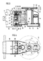
- a tool holder unit 9 essentially comprises a tool holder spindle 13 whose rotation is ensured by a motor 14 by means of pulleys 15 and 16 and a belt 17; the spindle 13 and the motor 14 are fixed to a structural part 18; the structural part 18 is connected to another structural part 19 by means of columns 20 and has, with respect to this structural part 19, a degree of freedom of movement along these columns 20. the structural part 19 is fixed to the support and positioning device 8.
- a part 21 comprising a bearing surface 22 is connected to the structural part 18 by through a net 23; the rotation of this part 21 relative to the structural part 18 generates a displacement of the part 21 relative to the structural part 18 along the axis 24; this rotation is printed and controlled by a micromotor 25 via pulleys 26 and 27 and a belt 28; similarly, a part 29 comprising a bearing surface 30 is connected to the structural part 18 by means of a thread 31; the rotation of this part 29 relative to the structural part 18 generates a displacement of the part 29 relative to the structural part 18 along the axis 32; this rotation is printed and controlled by a micromotor 33 via pulleys 34 and 35 and a belt 36.
- the micromotors 25 and 33 are controlled by a logic or computer unit.
- a piston 37 slides in a housing 38 arranged in the structural part 19; its maximum stroke is determined by the position of the underside of the stop piece 39. Left to itself, the piston 37 is in the low position; it is pushed into the high position by a pressurized fluid supplied via the pipe 40 at the level of the underside of the piston 37.
- the surface 22 of the part 21 is always in contact with the upper face 41 of the piston 37; the piston 37 being in the low position if the line 40 is not supplied by the pressurized fluid or in the high position if the line 40 is supplied by the fluid under pressure.
- the functional stroke of the piston the maximum stroke of which is determined by the height of the cylindrical chamber which remains free in the housing 38, is determined by the existing distance, the piston being in the low position, between the bearing surface 30 of the part 29 and the underside 42 of the structural part 19. This distance can vary by the displacement along the axis 32 of the part 29 generated and controlled by the rotation of the micromotor 33, the functional stroke of the piston 37 is therefore adjustable.
- the movement of the part 21 relative to the structural part 18 being generated and controlled by the rotation of the micromotor 25, the position, the piston 37 being in the low position, of the structural part 18 relative to the part structure 19, that is to say in fact the position of the plane of symmetry of the cutting disc 10 relative to the support and positioning device 8, is also adjustable.
- the article carrying head 4 is designed in such a way that the clamping vice 5 carrying the article 47 can be rotated controlled in terms of angular position, rotational speed and angular acceleration by the through a logical or computer unit.
- the positioning device 6 controlling the movement of the upper cross member 3 along the columns 2 is generally controlled by a logic or computer unit.
- the movements of the two tool-holding units 9 along the support and positioning device 8 are generally independent of one another and controlled by a logic or computer unit so that these movements can be synchronized with the rotation of the clamping vice 5 carrying the article 47 and the displacement of the cross-member 3 so as to machine in the best conditions articles of complex or irregular shapes.
- the speed of rotation of tools 10 and 11 is also adjustable.
- the article 47 is loaded manually or by an automated device on the article holder head 4, the cap 48 constituting the lower part of the mass of glass or crystal constituting the article to be machined.
- the tools 10 and 11 are rotated.
- the cutting operation is carried out firstly by the two abrasive discs 10 working substantially simultaneously; at this time, the piston 37 is held in the high position by the pressurized fluid supplied via the pipe 40; beforehand, the two cutting discs 10 were brought into the same substantially horizontal plane by the adjustment of the bearing surfaces 30.
- the two cutting discs 10 penetrate into the article to be cut in places and in directions of substantially opposite approach substantially simultaneously by displacements, parallel to themselves, in their substantially horizontal common plane and perpendicular to the axis 24, materialized by the displacements of the tool holders 9 along the support and positioning device 8.
- article 47 is slowly rotated.
- the grooves produced by the discs 10 during the rotation of the article 47 lead to the detachment of the cap 48 after a rotation less than or equal to 180 °.
- a first flattering operation can optionally be carried out with the upper face 44 of the part as the flattering tool. diamond 43 of the cutting disc 10.
- the cutting discs 10 are brought into a favorable position for this flattering operation by a displacement, parallel to themselves, in their common plane substantially horizontal and perpendicular to the axis 24, materialized by the displacements of the tool holders 9 along the support and positioning device 8.
- the relative positions of the two cutting discs 10 relative to the article 47 along the axis 24 being substantially identical, an identical depression of the lateral face upper 44 of these two discs 10 is determined by an equivalent displacement of the cross-member 3 along the columns 2, this displacement being precisely controlled by the positioning device 6.
- This distance has been adjusted beforehand and for each tool holder unit by the position of the bearing surface 22, given the position of the bearing surface 30, at a value slightly greater than the distance, projected on the axis 24, between the upper face 44 of the abrasive part 43 of the cutting disc 10 and the upper face 46 of the abrasive part 45 of the flatter wheel 11 so as to be able to bring without risk of interference with article 47 which has just been cut off the flatter wheel 11 under this article, in a position favorable for the flattering operation .
- the values of this distance will generally not be exactly the same for the two tool-holding units; they can be significantly different if the abrasive tools, and in particular the flattering wheels 11 are of different types or at different stages of wear.
- the flattering operation can begin; it can be carried out by only one of the two grinding wheels 11; in this case, the two grinding wheels 11 can be of equal quality and be used alternately; the two grinding wheels 11 can also be different and used successively on the same article.
- the flattering operation can also be carried out by the two grinding wheels 11 working substantially simultaneously; in this case, the two grinding wheels 11 are generally of equal quality.
- the progressive sinking of the grinding wheels 11 can be precisely controlled by the displacement of the cross-member 3 along the columns 2. It is also possible to allow the sinking to occur freely as the removal of the material constituting the article by the abrasive wheel; in this case, it is the force of application of the grinding wheel on the article which is controlled by means of the fluid pressure applied to the underside of the piston 37, the stop 30 coming into contact with the underside 42 of the structural part 19 to limit the insertion of the grinding wheel into the article.
- the driving-in distance of the abrasive wheel 11 during flattering being generally different from the distance between the upper face 44 of the abrasive part 43 of the cutting disc 10 and the upper face 46 of the abrasive part 45 of the flattering wheel 11, the setting of the stop 30 must, according to this way of working, be modified twice during each cycle of cutting-fletting combined.
- the distance between the bearing surface 30 and the underside 42 of the workpiece structure 19, the piston 37 being in the low position can be kept equal to the driving-in distance of the grinding wheel 11 in the article 47 during the flattering operation, a complementary and sufficient movement of the cross-member 3 along the columns 2 between the cutting and flattering operations allowing the grinding wheel 11 under the article 47 to be brought into the flattering position without risk of interference.
- a machine carrying out the combined cutting-planking operation as well as an additional finishing operation is advantageously made up of the combination of two combined cutting-planking devices represented in FIG. 5 by the references 1,2,3,4,6 , 7,8 and 9 placed face to face and each constituting a main work station operating simultaneously in cycles offset in time and whose loading is carried out alternately and automatically by two arms 49 themselves supplied manually or automatically from 'same loading station 50.
- the loading arms include a telescopic extension device so that the article 47 which has just been unloaded from one of the cutting-fletting devices can be presented at a work station 51 where an auxiliary finishing operation is carried out.
Landscapes
- Engineering & Computer Science (AREA)
- Mechanical Engineering (AREA)
- Mining & Mineral Resources (AREA)
- Chemical & Material Sciences (AREA)
- Ceramic Engineering (AREA)
- Inorganic Chemistry (AREA)
- Re-Forming, After-Treatment, Cutting And Transporting Of Glass Products (AREA)
- Grinding And Polishing Of Tertiary Curved Surfaces And Surfaces With Complex Shapes (AREA)
- Finish Polishing, Edge Sharpening, And Grinding By Specific Grinding Devices (AREA)
- Crystals, And After-Treatments Of Crystals (AREA)
Claims (4)
Priority Applications (1)
| Application Number | Priority Date | Filing Date | Title |
|---|---|---|---|
| AT89870069T ATE77985T1 (de) | 1988-05-26 | 1989-05-23 | Verfahren zum kombinierten schneiden und nachbearbeiten von glaswaren oder kristallwaren mittels abrasiver werkzeuge und vorrichtung zur durchfuehrung des verfahrens. |
Applications Claiming Priority (2)
| Application Number | Priority Date | Filing Date | Title |
|---|---|---|---|
| BE8800583 | 1988-05-26 | ||
| BE8800583A BE1002045A4 (fr) | 1988-05-26 | 1988-05-26 | Procede de tronconnage-flettage combines a l'aide d'outils abrasifs d'articles de verrerie ou de cristallerie et dispositif mettant en oeuvre le procede. |
Publications (2)
| Publication Number | Publication Date |
|---|---|
| EP0344142A1 EP0344142A1 (de) | 1989-11-29 |
| EP0344142B1 true EP0344142B1 (de) | 1992-07-08 |
Family
ID=3883424
Family Applications (1)
| Application Number | Title | Priority Date | Filing Date |
|---|---|---|---|
| EP89870069A Expired - Lifetime EP0344142B1 (de) | 1988-05-26 | 1989-05-23 | Verfahren zum kombinierten Schneiden und Nachbearbeiten von Glaswaren oder Kristallwaren mittels abrasiver Werkzeuge und Vorrichtung zur Durchführung des Verfahrens |
Country Status (6)
| Country | Link |
|---|---|
| US (1) | US4982531A (de) |
| EP (1) | EP0344142B1 (de) |
| JP (1) | JP2819150B2 (de) |
| AT (1) | ATE77985T1 (de) |
| BE (1) | BE1002045A4 (de) |
| DE (1) | DE68902012T2 (de) |
Families Citing this family (8)
| Publication number | Priority date | Publication date | Assignee | Title |
|---|---|---|---|---|
| KR20000047941A (ko) * | 1998-12-07 | 2000-07-25 | 세야 히로미치 | 유리 퍼널 시일 엣지를 연마하기 위한 방법 및 그 연마 장비 |
| US6712061B1 (en) | 2001-02-20 | 2004-03-30 | Robert M. Kalb | Portable apparatus for working, shaping and polishing stone and other hard materials |
| US9533430B1 (en) | 2011-10-18 | 2017-01-03 | Robert M. Kalb | Portable adjustable cutting apparatus for cutting and shaping sink holes in stone countertops |
| JPWO2014050376A1 (ja) * | 2012-09-25 | 2016-08-22 | コニカミノルタ株式会社 | ガラス部品の製造方法 |
| CN105082377B (zh) * | 2014-05-07 | 2017-05-10 | 洛阳金诺机械工程有限公司 | 一种板状晶体的切割装置 |
| CN106363782A (zh) * | 2016-08-31 | 2017-02-01 | 宁波诺亚智能设备有限公司 | 一种陶粒砖块切割流水线中的平切机 |
| CN108638341B (zh) * | 2018-07-26 | 2019-08-16 | 佛山市顺德区优畅玻璃有限公司 | 一种玻璃边框切割装置 |
| CN113896411B (zh) * | 2021-11-03 | 2022-06-07 | 连云港福东正佑照明电器有限公司 | 一种高精度的石英玻璃加工用切割设备及加工方法 |
Family Cites Families (11)
| Publication number | Priority date | Publication date | Assignee | Title |
|---|---|---|---|---|
| US117208A (en) * | 1871-07-18 | Improvement in apparatus for cutting glass globes | ||
| US2524323A (en) * | 1947-02-21 | 1950-10-03 | Carysfort F Lloyd-Young | Cutting and sanding device |
| DE1477659A1 (de) * | 1965-01-07 | 1969-06-04 | Pittler Ag Maschf | Saegemaschine zum Zerschneiden von Stangenmaterial zu laengsdurchbrochenen Werkstueckrohlingen |
| CH446098A (fr) * | 1965-10-04 | 1967-10-31 | Biebuyck Sa Ets | Machine à rectifier des bords de verre |
| US3753430A (en) * | 1972-06-14 | 1973-08-21 | E Oas | Saw-grinder combination for thin rock section machines |
| SU592576A1 (ru) * | 1975-09-09 | 1978-02-15 | Предприятие П/Я Х-5382 | Устройство дл шлифовани изделий |
| DE2700487B2 (de) * | 1977-01-07 | 1980-07-31 | Emil 8372 Zwiesel Ilk | Abspreng- und Schleifautomat für Gläser |
| US4475527A (en) * | 1982-06-11 | 1984-10-09 | The United States Of America As Represented By The Administrator Of The National Aeronautics And Space Administration | Ingot slicing machine and method |
| US4633621A (en) * | 1985-11-07 | 1987-01-06 | Weber Raymond R | Portable cutoff and end-beveling device |
| GB8531727D0 (en) * | 1985-12-24 | 1986-02-05 | Abbeybench Ltd | Glassware grinding/polishing apparatus |
| DE3884903T2 (de) * | 1987-10-29 | 1994-02-10 | Tokyo Seimitsu Co Ltd | Vorrichtung und Verfahren zum Abschneiden einer Halbleiterscheibe. |
-
1988
- 1988-05-26 BE BE8800583A patent/BE1002045A4/fr not_active IP Right Cessation
-
1989
- 1989-05-23 AT AT89870069T patent/ATE77985T1/de not_active IP Right Cessation
- 1989-05-23 DE DE8989870069T patent/DE68902012T2/de not_active Expired - Fee Related
- 1989-05-23 EP EP89870069A patent/EP0344142B1/de not_active Expired - Lifetime
- 1989-05-24 US US07/356,744 patent/US4982531A/en not_active Expired - Lifetime
- 1989-05-25 JP JP1130297A patent/JP2819150B2/ja not_active Expired - Fee Related
Also Published As
| Publication number | Publication date |
|---|---|
| DE68902012D1 (de) | 1992-08-13 |
| DE68902012T2 (de) | 1993-02-11 |
| US4982531A (en) | 1991-01-08 |
| JP2819150B2 (ja) | 1998-10-30 |
| JPH0215967A (ja) | 1990-01-19 |
| EP0344142A1 (de) | 1989-11-29 |
| BE1002045A4 (fr) | 1990-06-05 |
| ATE77985T1 (de) | 1992-07-15 |
Similar Documents
| Publication | Publication Date | Title |
|---|---|---|
| EP1606079B1 (de) | Maschine zum schleifen von optischen linsen | |
| FR2808464A1 (fr) | Machine a meuler et procede pour affuter des lames | |
| EP2366497B1 (de) | Grob- und Feinbearbeitungsmaschine | |
| EP0344142B1 (de) | Verfahren zum kombinierten Schneiden und Nachbearbeiten von Glaswaren oder Kristallwaren mittels abrasiver Werkzeuge und Vorrichtung zur Durchführung des Verfahrens | |
| EP1935564B1 (de) | Endbearbeitungsmaschine | |
| FR2465577A1 (fr) | Machine pour le travail du bois a tourelles portant plusieurs outils amenes selectivement en position de travail | |
| KR101868107B1 (ko) | 디버링 장치 | |
| GB2342060A (en) | Wafer edge polishing | |
| FR2778357A1 (fr) | Procede et appareil d'execution d'operations d'usinage sur une surface d'une ou plusieurs lentilles | |
| CH658216A5 (fr) | Procede de finissage de pieces moulees ou usinees et centre de finissage pour la mise en oeuvre de ce procede. | |
| EP0257013B1 (de) | Verfahren und Vorrichtung zum mechanischen Schleifen und Polieren der Fläche eines mineralischen Materials, insbesondere aus Glas | |
| EP0588713B1 (de) | Fräs-, Planfräs- und Polier-Maschine für automatischen Werkzeugwechsel und entsprechende Vorrichtung | |
| FR2515692A1 (fr) | Dispositif de nettoyage de barres porte-anode pour bains de fusion electrolytiques d'aluminium | |
| FR2527971A1 (fr) | Procede et appareil pour ebarber un objet plat en ceramique | |
| EP0345239A1 (de) | Topfschleifscheibe und Verwendung derselben zum Schleifen und mechanischen Polieren von Glas | |
| FR2658111A1 (fr) | Machine a decouper les tissus ou d'autres materiaux en feuilles pourvue d'une butee de fin de course reglable pour un couteau de decoupage. | |
| EP0477070B1 (de) | Herstellung von verarbeitetem Glasscheiben mit numerischer Steuerung | |
| US4209005A (en) | Apparatus for cutting silicon having a pivoted work carriage utilizing an air bearing | |
| CN210756772U (zh) | 基于高精度多工位加工工艺的手工刀具开刃打磨设备 | |
| US943191A (en) | Gem-cutting machine. | |
| CN218556457U (zh) | 一种精密刀具磨床用刀具装夹装置 | |
| JPH05318226A (ja) | 鋸刃形成ユニット | |
| FR2821779A1 (fr) | Machine a rectifier cylindrique, notamment du type a grande vitesse | |
| JP2014030875A (ja) | 歯車加工装置 | |
| FR2537044A1 (fr) | Machine pour tailler une surface plane dans des blocs de pierre |
Legal Events
| Date | Code | Title | Description |
|---|---|---|---|
| PUAI | Public reference made under article 153(3) epc to a published international application that has entered the european phase |
Free format text: ORIGINAL CODE: 0009012 |
|
| AK | Designated contracting states |
Kind code of ref document: A1 Designated state(s): AT CH DE ES FR GB GR IT LI LU NL SE |
|
| 17P | Request for examination filed |
Effective date: 19891227 |
|
| 17Q | First examination report despatched |
Effective date: 19901022 |
|
| GRAA | (expected) grant |
Free format text: ORIGINAL CODE: 0009210 |
|
| AK | Designated contracting states |
Kind code of ref document: B1 Designated state(s): AT CH DE ES FR GB GR IT LI LU NL SE |
|
| PG25 | Lapsed in a contracting state [announced via postgrant information from national office to epo] |
Ref country code: NL Effective date: 19920708 Ref country code: GR Free format text: LAPSE BECAUSE OF FAILURE TO SUBMIT A TRANSLATION OF THE DESCRIPTION OR TO PAY THE FEE WITHIN THE PRESCRIBED TIME-LIMIT Effective date: 19920708 Ref country code: ES Free format text: THE PATENT HAS BEEN ANNULLED BY A DECISION OF A NATIONAL AUTHORITY Effective date: 19920708 |
|
| REF | Corresponds to: |
Ref document number: 77985 Country of ref document: AT Date of ref document: 19920715 Kind code of ref document: T |
|
| REF | Corresponds to: |
Ref document number: 68902012 Country of ref document: DE Date of ref document: 19920813 |
|
| GBT | Gb: translation of ep patent filed (gb section 77(6)(a)/1977) | ||
| ITF | It: translation for a ep patent filed | ||
| NLV1 | Nl: lapsed or annulled due to failure to fulfill the requirements of art. 29p and 29m of the patents act | ||
| PLBE | No opposition filed within time limit |
Free format text: ORIGINAL CODE: 0009261 |
|
| STAA | Information on the status of an ep patent application or granted ep patent |
Free format text: STATUS: NO OPPOSITION FILED WITHIN TIME LIMIT |
|
| PG25 | Lapsed in a contracting state [announced via postgrant information from national office to epo] |
Ref country code: LU Free format text: LAPSE BECAUSE OF NON-PAYMENT OF DUE FEES Effective date: 19930531 Ref country code: LI Effective date: 19930531 Ref country code: CH Effective date: 19930531 |
|
| 26N | No opposition filed | ||
| REG | Reference to a national code |
Ref country code: CH Ref legal event code: PL |
|
| EAL | Se: european patent in force in sweden |
Ref document number: 89870069.5 |
|
| REG | Reference to a national code |
Ref country code: GB Ref legal event code: IF02 |
|
| PGFP | Annual fee paid to national office [announced via postgrant information from national office to epo] |
Ref country code: GB Payment date: 20030328 Year of fee payment: 15 |
|
| PGFP | Annual fee paid to national office [announced via postgrant information from national office to epo] |
Ref country code: AT Payment date: 20030424 Year of fee payment: 15 |
|
| PGFP | Annual fee paid to national office [announced via postgrant information from national office to epo] |
Ref country code: SE Payment date: 20030519 Year of fee payment: 15 |
|
| PGFP | Annual fee paid to national office [announced via postgrant information from national office to epo] |
Ref country code: FR Payment date: 20030526 Year of fee payment: 15 |
|
| PGFP | Annual fee paid to national office [announced via postgrant information from national office to epo] |
Ref country code: DE Payment date: 20030530 Year of fee payment: 15 |
|
| PG25 | Lapsed in a contracting state [announced via postgrant information from national office to epo] |
Ref country code: GB Free format text: LAPSE BECAUSE OF NON-PAYMENT OF DUE FEES Effective date: 20040523 Ref country code: AT Free format text: LAPSE BECAUSE OF NON-PAYMENT OF DUE FEES Effective date: 20040523 |
|
| PG25 | Lapsed in a contracting state [announced via postgrant information from national office to epo] |
Ref country code: SE Free format text: LAPSE BECAUSE OF NON-PAYMENT OF DUE FEES Effective date: 20040524 |
|
| PG25 | Lapsed in a contracting state [announced via postgrant information from national office to epo] |
Ref country code: DE Free format text: LAPSE BECAUSE OF NON-PAYMENT OF DUE FEES Effective date: 20041201 |
|
| EUG | Se: european patent has lapsed | ||
| GBPC | Gb: european patent ceased through non-payment of renewal fee |
Effective date: 20040523 |
|
| PG25 | Lapsed in a contracting state [announced via postgrant information from national office to epo] |
Ref country code: FR Free format text: LAPSE BECAUSE OF NON-PAYMENT OF DUE FEES Effective date: 20050131 |
|
| REG | Reference to a national code |
Ref country code: FR Ref legal event code: ST |
|
| PGFP | Annual fee paid to national office [announced via postgrant information from national office to epo] |
Ref country code: IT Payment date: 20060531 Year of fee payment: 18 |
|
| PG25 | Lapsed in a contracting state [announced via postgrant information from national office to epo] |
Ref country code: IT Free format text: LAPSE BECAUSE OF NON-PAYMENT OF DUE FEES Effective date: 20070523 |