EP0344074A2 - Abnehmbare Ionisationskammer für Abgasreiniger, insbesondere für Luft - Google Patents
Abnehmbare Ionisationskammer für Abgasreiniger, insbesondere für Luft Download PDFInfo
- Publication number
- EP0344074A2 EP0344074A2 EP89402071A EP89402071A EP0344074A2 EP 0344074 A2 EP0344074 A2 EP 0344074A2 EP 89402071 A EP89402071 A EP 89402071A EP 89402071 A EP89402071 A EP 89402071A EP 0344074 A2 EP0344074 A2 EP 0344074A2
- Authority
- EP
- European Patent Office
- Prior art keywords
- sheet
- coated
- purifier according
- ionization chamber
- face
- Prior art date
- Legal status (The legal status is an assumption and is not a legal conclusion. Google has not performed a legal analysis and makes no representation as to the accuracy of the status listed.)
- Withdrawn
Links
Images
Classifications
-
- B—PERFORMING OPERATIONS; TRANSPORTING
- B03—SEPARATION OF SOLID MATERIALS USING LIQUIDS OR USING PNEUMATIC TABLES OR JIGS; MAGNETIC OR ELECTROSTATIC SEPARATION OF SOLID MATERIALS FROM SOLID MATERIALS OR FLUIDS; SEPARATION BY HIGH-VOLTAGE ELECTRIC FIELDS
- B03C—MAGNETIC OR ELECTROSTATIC SEPARATION OF SOLID MATERIALS FROM SOLID MATERIALS OR FLUIDS; SEPARATION BY HIGH-VOLTAGE ELECTRIC FIELDS
- B03C3/00—Separating dispersed particles from gases or vapour, e.g. air, by electrostatic effect
- B03C3/34—Constructional details or accessories or operation thereof
- B03C3/38—Particle charging or ionising stations, e.g. using electric discharge, radioactive radiation or flames
-
- B—PERFORMING OPERATIONS; TRANSPORTING
- B03—SEPARATION OF SOLID MATERIALS USING LIQUIDS OR USING PNEUMATIC TABLES OR JIGS; MAGNETIC OR ELECTROSTATIC SEPARATION OF SOLID MATERIALS FROM SOLID MATERIALS OR FLUIDS; SEPARATION BY HIGH-VOLTAGE ELECTRIC FIELDS
- B03C—MAGNETIC OR ELECTROSTATIC SEPARATION OF SOLID MATERIALS FROM SOLID MATERIALS OR FLUIDS; SEPARATION BY HIGH-VOLTAGE ELECTRIC FIELDS
- B03C3/00—Separating dispersed particles from gases or vapour, e.g. air, by electrostatic effect
- B03C3/32—Transportable units, e.g. for cleaning room air
-
- B—PERFORMING OPERATIONS; TRANSPORTING
- B03—SEPARATION OF SOLID MATERIALS USING LIQUIDS OR USING PNEUMATIC TABLES OR JIGS; MAGNETIC OR ELECTROSTATIC SEPARATION OF SOLID MATERIALS FROM SOLID MATERIALS OR FLUIDS; SEPARATION BY HIGH-VOLTAGE ELECTRIC FIELDS
- B03C—MAGNETIC OR ELECTROSTATIC SEPARATION OF SOLID MATERIALS FROM SOLID MATERIALS OR FLUIDS; SEPARATION BY HIGH-VOLTAGE ELECTRIC FIELDS
- B03C3/00—Separating dispersed particles from gases or vapour, e.g. air, by electrostatic effect
- B03C3/34—Constructional details or accessories or operation thereof
- B03C3/36—Controlling flow of gases or vapour
-
- B—PERFORMING OPERATIONS; TRANSPORTING
- B03—SEPARATION OF SOLID MATERIALS USING LIQUIDS OR USING PNEUMATIC TABLES OR JIGS; MAGNETIC OR ELECTROSTATIC SEPARATION OF SOLID MATERIALS FROM SOLID MATERIALS OR FLUIDS; SEPARATION BY HIGH-VOLTAGE ELECTRIC FIELDS
- B03C—MAGNETIC OR ELECTROSTATIC SEPARATION OF SOLID MATERIALS FROM SOLID MATERIALS OR FLUIDS; SEPARATION BY HIGH-VOLTAGE ELECTRIC FIELDS
- B03C3/00—Separating dispersed particles from gases or vapour, e.g. air, by electrostatic effect
- B03C3/34—Constructional details or accessories or operation thereof
- B03C3/40—Electrode constructions
- B03C3/60—Use of special materials other than liquids
Definitions
- the present invention relates to air purifiers that are installed in premises in order to purify the atmosphere.
- the known purifiers are of different types but all have a fairly poor performance due in particular to a poor design of the structure which provides for an air path which is poorly coordinated with the requirements of the electric field to be created in an ionization chamber.
- the invention provides a new solution to the problem of air purification in rooms by proposing a rational structure which greatly improves the flow of air in the room and inside the purifier itself.
- the invention relates to gas purifiers which contain an ionization chamber traversed by a taut conductive wire through which must pass a high voltage electric current (of the order of 10,000 volts) to create an electric field through which particles in suspension in the gas are ionized and are, therefore, biased towards the internal metal walls of the chamber on which they are deposited for their collection.
- a high voltage electric current of the order of 10,000 volts
- the need for the walls of the chamber to be conductive leads the manufacturers to produce the metal chamber. They are essentially smooth sheets, relatively thick and heavy to be robust, which requires the presence of holding and fixing members to avoid, in particular, the displacements, beats and vibrations due to the displacement of the pulsed gas by a wind tunnel.
- the chambers are therefore very removable, in the strict sense of the word, but on condition of carrying out a real disassembly followed by a reassembly, and this requires the use of tools. Their price is such that they must be cleaned and not replaced.
- the internal walls of the chamber should be rough during operation in order to effectively retain the deposited and smooth particles at the time of cleaning so that it is easy and complete.
- the invention relates to a gas purifier, in particular air, of the type comprising a box provided with at least one inlet and at least one outlet and containing a profiled ionization chamber for guiding aerodynamics of the gas flow from the inlet to the outlet, characterized in that the ionization chamber is formed at least partially by a sheet of cardboard or similar material stored flat and which must be removably placed in the box after folding and / or bending, the face of this sheet which must be on the internal side of the ionization chamber being coated with a bare conductive material, such as aluminum not coated with an insulating product.
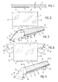
- Figure 1 is a schematic sectional view of a sheet according to the invention.
- Figure 2 is a plan view of a sheet according to the invention, seen from its smoother side.
- Figure 3 is a schematic perspective view showing the sheet of Figure 1 bent and folded as it is when held in its place of function.
- FIG. 4 is a plan view of a sheet in accordance with the invention, seen from its smoothest side and produced according to a variant different from that of FIG. 5.
- Figure 5 is a schematic perspective view showing the sheet of Figure 8 bent and folded as it is when held in its place of function.
- a sheet according to the invention is made of cardboard and has a very smooth face 1 and a less smooth face 2.
- This difference may arise from the manufacturing method which provides that in during development, the fibers which are still wet constitute a very fragile and cohesive sheet which is supported by being placed on a carpet or other non-smooth support which communicates its surface irregularities to it, or which provides for the calendering of the sheet for the compress, one of the cylinders of the calender being polished so that the corresponding face 1 is smooth while the opposite cylinder has a rough surface, more or less regular, which provides a complementary surface on face 2.
- This can also come from a coating of face 1.
- the face 1 being more noble is chosen to receive a coating, in particular a thin aluminum sheet, because we are looking for the regularity and softness of the worked face.
- the rough and more or less voluntarily marked face 2 is disposed on the hidden side and is particularly suitable for coating adhesives.
- the coating 3 can be constituted by an aluminum sheet which will not have the glossy appearance which it has when it is well stretched or which it would have if it had been applied against the face 1. It therefore acquires, by using it thus, a new particular quality with regard to the retention of ionized particles, without losing at all its qualities of electrical conductivity.
- FIG. 2 we see an example of a sheet constituted as said above with reference to FIG. 1 and having two transverse rectilinear creasing lines 4 and 5 which determine two margins 6 and 7.
- the new sheets are stored at flat and thus occupy little volume. They can be assembled in groups and possibly packed in boxes, with separators to protect the covering 3 against knocks and tears.
- the sheet has free edges 8 and 9 which do not create sides to the ionization chamber.
- the sheet can be maintained by any means, in particular by a stirrup which is immobilized using the blocking resulting from the closure of the box by a cover or the like.
- the sheet is advantageously made of cardboard, due to the excellent behavior of this material and its acoustic qualities which give the assurance that the operation of the device will be very silent.
- the cardboard also has the advantage of having a substantial thickness E and of being flexible. We can then use these mechanical characteristics to immobilize the sheet by a simple wedging or pinching of the margins 6 and 7. This is obviously not the case with the metal which is rigid, thin, slippery and noisy when it vibrates or when it taps another metal piece.
- the ionization chamber is formed by the sheet in the position of FIG. 3.
- the gas which can be the air of premises for example, is sucked by the entry by means turbines and it is guided by deflectors at the entrance of the chamber, that is to say under the edge formed by the creasing line 5. It is thus pulsed in the electric field generated between the wire A and the conductive face of the sheet, namely the coating 3.
- the particles and dust are ionized and are plated on the coating 3 which retains them all the better as its surface is not very smooth.
- the purified air leaves the ionization chamber in the vicinity of the edge of the sheet formed by the creasing line 4 and leaves the device.
- the sheet is continuously charged with dust when the device is operating and, after a certain period of time which can be a few days or a few weeks, the sheet is as "saturated", that is to say that the electric field becomes less intense because the conductivity of the coating 3 attenuates as and when the dust accumulates and the roughness offered to these dusts so that they cling to it dulls by filling the hollows.
- the box of the apparatus is opened, the sheet is removed, it is replaced by another new taken from the stock and shaped as in FIG. 3.
- the worn leaf is discarded.
- the price of the new sheet is low enough and the intervention time is short enough that the repair operation is significantly less expensive than the cleaning that is currently required.
- the replacement of one sheet by another can be so simple that one can consider entrusting it to the user himself, thus avoiding the displacement of qualified personnel.
- FIG. 4 a variant is shown according to which the new sheet presented flat is integral with two lateral cheeks 10 and 11 determined by rectilinear creasing lines 12 and 13 substantially aligned with the free edges 14 and 15 of the sheet.
- the shaping of this sheet is done by first folding the cheeks 10 and 11 along the creasing lines 12 and 13 inward, namely towards the face 2 carrying the coating 3, and then bending the whole sheet as shown in FIG. 5.
- the margins 6 and 7 are also provided here, but by providing for the presence of cheeks, these can be combined with holding means which would make the creasing lines 4 and 5 and the margins 6 and 7 unnecessary.
- cheeks 10 and 11 each have a notch respectively 18 and 19 which allows them to best adapt to the shape of the interior of the box and to the presence of elements such as deflector, turbines etc. in order to avoid leaks and pressure losses as much as possible.
Landscapes
- Electrostatic Separation (AREA)
Applications Claiming Priority (2)
| Application Number | Priority Date | Filing Date | Title |
|---|---|---|---|
| FR8704312 | 1987-03-27 | ||
| FR8704312 | 1987-03-27 |
Related Parent Applications (2)
| Application Number | Title | Priority Date | Filing Date |
|---|---|---|---|
| EP88400750A Division EP0288351A3 (de) | 1987-03-27 | 1988-03-28 | Abgasreiniger, insbesondere für Luft, mit einer Ionisationskammer |
| EP88400750.1 Division | 1988-03-28 |
Publications (2)
| Publication Number | Publication Date |
|---|---|
| EP0344074A2 true EP0344074A2 (de) | 1989-11-29 |
| EP0344074A3 EP0344074A3 (de) | 1990-03-07 |
Family
ID=9349509
Family Applications (1)
| Application Number | Title | Priority Date | Filing Date |
|---|---|---|---|
| EP89402071A Withdrawn EP0344074A3 (de) | 1987-03-27 | 1988-03-28 | Abnehmbare Ionisationskammer für Abgasreiniger, insbesondere für Luft |
Country Status (1)
| Country | Link |
|---|---|
| EP (1) | EP0344074A3 (de) |
Family Cites Families (3)
| Publication number | Priority date | Publication date | Assignee | Title |
|---|---|---|---|---|
| GB646577A (en) * | 1946-08-27 | 1950-11-22 | Westinghouse Electric Int Co | Improvements in or relating to electrostatic precipitators |
| DE2427759A1 (de) * | 1974-06-08 | 1976-01-02 | Miele & Cie | Elektrostatischer luftfilter |
| FR2583657A1 (fr) * | 1985-06-20 | 1986-12-26 | Mingret Sa Ateliers R | Dispositif de nettoyage de l'air |
-
1988
- 1988-03-28 EP EP89402071A patent/EP0344074A3/de not_active Withdrawn
Also Published As
| Publication number | Publication date |
|---|---|
| EP0344074A3 (de) | 1990-03-07 |
Similar Documents
| Publication | Publication Date | Title |
|---|---|---|
| EP3479730B1 (de) | Vorrichtung zur ausgabe künstlicher wimpern | |
| FR2560423A1 (fr) | Procede et dispositif de protection d'assemblages combustibles nucleaires | |
| WO2017005939A1 (fr) | Dispositif de distribution de cils artificiels comprenant un element de maintien des cils | |
| EP0255425B1 (de) | Gerät zum automatischen Auflegen einer Fasermatte auf eine Form, sowie Vorrichtungen mit einem derartigen Gerät | |
| FR2640948A1 (de) | ||
| EP0191786A1 (de) | Filterkerze mit einer hohen aussenoberfläche und verfahren zur herstellung. | |
| FR2842443A1 (fr) | Plaque metallique, son procede de fabrication et son procede de pliage | |
| EP0344074A2 (de) | Abnehmbare Ionisationskammer für Abgasreiniger, insbesondere für Luft | |
| EP0470240B1 (de) | Staubsauger | |
| WO1998004791A1 (fr) | Dalle de paroi a toile tendue | |
| FR2612805A1 (fr) | Epurateur de gaz, notamment d'air, comprenant une chambre d'ionisation jetable | |
| EP0288351A2 (de) | Abgasreiniger, insbesondere für Luft, mit einer Ionisationskammer | |
| FR2530837A1 (fr) | Dispositif pour retirer les particules de revelateur en exces sur la surface d'un element d'enregistrement | |
| FR2881147A1 (fr) | Carde comportant des moyens de recouvrement mobiles en translation | |
| EP0818602B1 (de) | Auf- und Abrollvorrichtung für ein Gewebe | |
| FR3059655B1 (fr) | Distributeur d'adhesif et dispositif de raccordement de gaines comportant un tel distributeur | |
| FR2690635A1 (fr) | Dispositif de protection pour un appareillage optique, et système optique comprenant un tel dispositif. | |
| FR2472927A1 (fr) | Dispositif de nettoyage a main | |
| FR2510153A1 (fr) | Machine a papier a guidage de toiles arque dans sa zone humide | |
| EP0352188A1 (de) | Stützrahmen für Filterelemente | |
| FR3109058A1 (fr) | Procédé de fabrication d’un masque de protection et masque ainsi obtenu | |
| CH621531A5 (en) | Device for continuously and automatically opening signatures intended to be assembled in order to form a book | |
| BE476111A (de) | ||
| CH626459A5 (en) | Machine for counting banknotes | |
| EP1590817B1 (de) | Dynamischer ofen für eine filmwickelmaschine |
Legal Events
| Date | Code | Title | Description |
|---|---|---|---|
| PUAI | Public reference made under article 153(3) epc to a published international application that has entered the european phase |
Free format text: ORIGINAL CODE: 0009012 |
|
| AC | Divisional application: reference to earlier application |
Ref document number: 288351 Country of ref document: EP |
|
| AK | Designated contracting states |
Kind code of ref document: A2 Designated state(s): AT BE CH DE ES FR GB GR IT LI LU NL SE |
|
| PUAL | Search report despatched |
Free format text: ORIGINAL CODE: 0009013 |
|
| RHK1 | Main classification (correction) |
Ipc: B03C 3/60 |
|
| AK | Designated contracting states |
Kind code of ref document: A3 Designated state(s): AT BE CH DE ES FR GB GR IT LI LU NL SE |
|
| 17P | Request for examination filed |
Effective date: 19900720 |
|
| 17Q | First examination report despatched |
Effective date: 19920129 |
|
| STAA | Information on the status of an ep patent application or granted ep patent |
Free format text: STATUS: THE APPLICATION IS DEEMED TO BE WITHDRAWN |
|
| 18D | Application deemed to be withdrawn |
Effective date: 19921001 |