EP0344074A2 - Removable ionisation chamber for a gas cleaner, especially of air - Google Patents
Removable ionisation chamber for a gas cleaner, especially of air Download PDFInfo
- Publication number
- EP0344074A2 EP0344074A2 EP89402071A EP89402071A EP0344074A2 EP 0344074 A2 EP0344074 A2 EP 0344074A2 EP 89402071 A EP89402071 A EP 89402071A EP 89402071 A EP89402071 A EP 89402071A EP 0344074 A2 EP0344074 A2 EP 0344074A2
- Authority
- EP
- European Patent Office
- Prior art keywords
- sheet
- coated
- purifier according
- ionization chamber
- face
- Prior art date
- Legal status (The legal status is an assumption and is not a legal conclusion. Google has not performed a legal analysis and makes no representation as to the accuracy of the status listed.)
- Withdrawn
Links
Images
Classifications
-
- B—PERFORMING OPERATIONS; TRANSPORTING
- B03—SEPARATION OF SOLID MATERIALS USING LIQUIDS OR USING PNEUMATIC TABLES OR JIGS; MAGNETIC OR ELECTROSTATIC SEPARATION OF SOLID MATERIALS FROM SOLID MATERIALS OR FLUIDS; SEPARATION BY HIGH-VOLTAGE ELECTRIC FIELDS
- B03C—MAGNETIC OR ELECTROSTATIC SEPARATION OF SOLID MATERIALS FROM SOLID MATERIALS OR FLUIDS; SEPARATION BY HIGH-VOLTAGE ELECTRIC FIELDS
- B03C3/00—Separating dispersed particles from gases or vapour, e.g. air, by electrostatic effect
- B03C3/34—Constructional details or accessories or operation thereof
- B03C3/38—Particle charging or ionising stations, e.g. using electric discharge, radioactive radiation or flames
-
- B—PERFORMING OPERATIONS; TRANSPORTING
- B03—SEPARATION OF SOLID MATERIALS USING LIQUIDS OR USING PNEUMATIC TABLES OR JIGS; MAGNETIC OR ELECTROSTATIC SEPARATION OF SOLID MATERIALS FROM SOLID MATERIALS OR FLUIDS; SEPARATION BY HIGH-VOLTAGE ELECTRIC FIELDS
- B03C—MAGNETIC OR ELECTROSTATIC SEPARATION OF SOLID MATERIALS FROM SOLID MATERIALS OR FLUIDS; SEPARATION BY HIGH-VOLTAGE ELECTRIC FIELDS
- B03C3/00—Separating dispersed particles from gases or vapour, e.g. air, by electrostatic effect
- B03C3/32—Transportable units, e.g. for cleaning room air
-
- B—PERFORMING OPERATIONS; TRANSPORTING
- B03—SEPARATION OF SOLID MATERIALS USING LIQUIDS OR USING PNEUMATIC TABLES OR JIGS; MAGNETIC OR ELECTROSTATIC SEPARATION OF SOLID MATERIALS FROM SOLID MATERIALS OR FLUIDS; SEPARATION BY HIGH-VOLTAGE ELECTRIC FIELDS
- B03C—MAGNETIC OR ELECTROSTATIC SEPARATION OF SOLID MATERIALS FROM SOLID MATERIALS OR FLUIDS; SEPARATION BY HIGH-VOLTAGE ELECTRIC FIELDS
- B03C3/00—Separating dispersed particles from gases or vapour, e.g. air, by electrostatic effect
- B03C3/34—Constructional details or accessories or operation thereof
- B03C3/36—Controlling flow of gases or vapour
-
- B—PERFORMING OPERATIONS; TRANSPORTING
- B03—SEPARATION OF SOLID MATERIALS USING LIQUIDS OR USING PNEUMATIC TABLES OR JIGS; MAGNETIC OR ELECTROSTATIC SEPARATION OF SOLID MATERIALS FROM SOLID MATERIALS OR FLUIDS; SEPARATION BY HIGH-VOLTAGE ELECTRIC FIELDS
- B03C—MAGNETIC OR ELECTROSTATIC SEPARATION OF SOLID MATERIALS FROM SOLID MATERIALS OR FLUIDS; SEPARATION BY HIGH-VOLTAGE ELECTRIC FIELDS
- B03C3/00—Separating dispersed particles from gases or vapour, e.g. air, by electrostatic effect
- B03C3/34—Constructional details or accessories or operation thereof
- B03C3/40—Electrode constructions
- B03C3/60—Use of special materials other than liquids
Definitions
- the present invention relates to air purifiers that are installed in premises in order to purify the atmosphere.
- the known purifiers are of different types but all have a fairly poor performance due in particular to a poor design of the structure which provides for an air path which is poorly coordinated with the requirements of the electric field to be created in an ionization chamber.
- the invention provides a new solution to the problem of air purification in rooms by proposing a rational structure which greatly improves the flow of air in the room and inside the purifier itself.
- the invention relates to gas purifiers which contain an ionization chamber traversed by a taut conductive wire through which must pass a high voltage electric current (of the order of 10,000 volts) to create an electric field through which particles in suspension in the gas are ionized and are, therefore, biased towards the internal metal walls of the chamber on which they are deposited for their collection.
- a high voltage electric current of the order of 10,000 volts
- the need for the walls of the chamber to be conductive leads the manufacturers to produce the metal chamber. They are essentially smooth sheets, relatively thick and heavy to be robust, which requires the presence of holding and fixing members to avoid, in particular, the displacements, beats and vibrations due to the displacement of the pulsed gas by a wind tunnel.
- the chambers are therefore very removable, in the strict sense of the word, but on condition of carrying out a real disassembly followed by a reassembly, and this requires the use of tools. Their price is such that they must be cleaned and not replaced.
- the internal walls of the chamber should be rough during operation in order to effectively retain the deposited and smooth particles at the time of cleaning so that it is easy and complete.
- the invention relates to a gas purifier, in particular air, of the type comprising a box provided with at least one inlet and at least one outlet and containing a profiled ionization chamber for guiding aerodynamics of the gas flow from the inlet to the outlet, characterized in that the ionization chamber is formed at least partially by a sheet of cardboard or similar material stored flat and which must be removably placed in the box after folding and / or bending, the face of this sheet which must be on the internal side of the ionization chamber being coated with a bare conductive material, such as aluminum not coated with an insulating product.
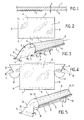
- Figure 1 is a schematic sectional view of a sheet according to the invention.
- Figure 2 is a plan view of a sheet according to the invention, seen from its smoother side.
- Figure 3 is a schematic perspective view showing the sheet of Figure 1 bent and folded as it is when held in its place of function.
- FIG. 4 is a plan view of a sheet in accordance with the invention, seen from its smoothest side and produced according to a variant different from that of FIG. 5.
- Figure 5 is a schematic perspective view showing the sheet of Figure 8 bent and folded as it is when held in its place of function.
- a sheet according to the invention is made of cardboard and has a very smooth face 1 and a less smooth face 2.
- This difference may arise from the manufacturing method which provides that in during development, the fibers which are still wet constitute a very fragile and cohesive sheet which is supported by being placed on a carpet or other non-smooth support which communicates its surface irregularities to it, or which provides for the calendering of the sheet for the compress, one of the cylinders of the calender being polished so that the corresponding face 1 is smooth while the opposite cylinder has a rough surface, more or less regular, which provides a complementary surface on face 2.
- This can also come from a coating of face 1.
- the face 1 being more noble is chosen to receive a coating, in particular a thin aluminum sheet, because we are looking for the regularity and softness of the worked face.
- the rough and more or less voluntarily marked face 2 is disposed on the hidden side and is particularly suitable for coating adhesives.
- the coating 3 can be constituted by an aluminum sheet which will not have the glossy appearance which it has when it is well stretched or which it would have if it had been applied against the face 1. It therefore acquires, by using it thus, a new particular quality with regard to the retention of ionized particles, without losing at all its qualities of electrical conductivity.
- FIG. 2 we see an example of a sheet constituted as said above with reference to FIG. 1 and having two transverse rectilinear creasing lines 4 and 5 which determine two margins 6 and 7.
- the new sheets are stored at flat and thus occupy little volume. They can be assembled in groups and possibly packed in boxes, with separators to protect the covering 3 against knocks and tears.
- the sheet has free edges 8 and 9 which do not create sides to the ionization chamber.
- the sheet can be maintained by any means, in particular by a stirrup which is immobilized using the blocking resulting from the closure of the box by a cover or the like.
- the sheet is advantageously made of cardboard, due to the excellent behavior of this material and its acoustic qualities which give the assurance that the operation of the device will be very silent.
- the cardboard also has the advantage of having a substantial thickness E and of being flexible. We can then use these mechanical characteristics to immobilize the sheet by a simple wedging or pinching of the margins 6 and 7. This is obviously not the case with the metal which is rigid, thin, slippery and noisy when it vibrates or when it taps another metal piece.
- the ionization chamber is formed by the sheet in the position of FIG. 3.
- the gas which can be the air of premises for example, is sucked by the entry by means turbines and it is guided by deflectors at the entrance of the chamber, that is to say under the edge formed by the creasing line 5. It is thus pulsed in the electric field generated between the wire A and the conductive face of the sheet, namely the coating 3.
- the particles and dust are ionized and are plated on the coating 3 which retains them all the better as its surface is not very smooth.
- the purified air leaves the ionization chamber in the vicinity of the edge of the sheet formed by the creasing line 4 and leaves the device.
- the sheet is continuously charged with dust when the device is operating and, after a certain period of time which can be a few days or a few weeks, the sheet is as "saturated", that is to say that the electric field becomes less intense because the conductivity of the coating 3 attenuates as and when the dust accumulates and the roughness offered to these dusts so that they cling to it dulls by filling the hollows.
- the box of the apparatus is opened, the sheet is removed, it is replaced by another new taken from the stock and shaped as in FIG. 3.
- the worn leaf is discarded.
- the price of the new sheet is low enough and the intervention time is short enough that the repair operation is significantly less expensive than the cleaning that is currently required.
- the replacement of one sheet by another can be so simple that one can consider entrusting it to the user himself, thus avoiding the displacement of qualified personnel.
- FIG. 4 a variant is shown according to which the new sheet presented flat is integral with two lateral cheeks 10 and 11 determined by rectilinear creasing lines 12 and 13 substantially aligned with the free edges 14 and 15 of the sheet.
- the shaping of this sheet is done by first folding the cheeks 10 and 11 along the creasing lines 12 and 13 inward, namely towards the face 2 carrying the coating 3, and then bending the whole sheet as shown in FIG. 5.
- the margins 6 and 7 are also provided here, but by providing for the presence of cheeks, these can be combined with holding means which would make the creasing lines 4 and 5 and the margins 6 and 7 unnecessary.
- cheeks 10 and 11 each have a notch respectively 18 and 19 which allows them to best adapt to the shape of the interior of the box and to the presence of elements such as deflector, turbines etc. in order to avoid leaks and pressure losses as much as possible.
Landscapes
- Electrostatic Separation (AREA)
Abstract
Description
La présente invention concerne les épurateurs d'air que l'on installe dans des locaux afin d'en purifier l'atmosphère.The present invention relates to air purifiers that are installed in premises in order to purify the atmosphere.
Les épurateurs connus sont de différents types mais ont tous un assez mauvais rendement dû en particulier à une mauvaise conception de la structure qui prévoit un cheminement d'air mal coordonné avec les impératifs du champ électrique à créer dans une chambre d'ionisation.The known purifiers are of different types but all have a fairly poor performance due in particular to a poor design of the structure which provides for an air path which is poorly coordinated with the requirements of the electric field to be created in an ionization chamber.
L'invention apporte une solution nouvelle au problème de l'épuration d'air des locaux en proposant une structure rationnelle qui améliore grandement le cheminement de l'air dans le local et à l'intérieur de l'épurateur lui-même.The invention provides a new solution to the problem of air purification in rooms by proposing a rational structure which greatly improves the flow of air in the room and inside the purifier itself.
En outre, l'invention concerne les épurateurs de gaz qui contiennent une chambre d' ionisation traversée par un fil conducteur tendu dans lequel doit passer un courant électrique à haute tension (de l'ordre de 10.000 Volts) pour créer un champ électrique par lequel des particules en suspension dans le gaz sont ionisées et sont, de ce fait, sollicitées vers les parois internes métalliques de la chambre sur lesquelles elles se déposent en vue de leur recueil.In addition, the invention relates to gas purifiers which contain an ionization chamber traversed by a taut conductive wire through which must pass a high voltage electric current (of the order of 10,000 volts) to create an electric field through which particles in suspension in the gas are ionized and are, therefore, biased towards the internal metal walls of the chamber on which they are deposited for their collection.
Les appareils existants sont peu pratiques car le recueil des poussières exige soit le démontage de la chambre d'ionisation et son nettoyage hors de l'appareil, soit une intervention sans démontage, auquel cas le risque est grand d'endommager le fil tendu qui est assez fragile. La personne qui agit doit alors prendre de grandes précautions et parvient rarement à un nettoyage complet. Les opérations de nettoyage sont indispensables à intervalles réguliers car l'efficacité de l'épuration dépend directement de la conductivité des parois de la chambre et leur rendement baisse au fur et à mesure que ces parois s'encrassent. Les difficultés du nettoyage rendent ces opérations coûteuses pour les utilisateurs qui ont tendance à les espacer pour des raisons d'économie, ce qui a évidemment pour conséquence une mauvaise épuration.Existing devices are impractical because collecting dust requires either disassembly of the ionization chamber and cleaning out of the device, or intervention without disassembly, in which case there is a great risk of damaging the taut wire which is quite fragile. The person who acts must therefore take great precautions and rarely achieve complete cleaning. The cleaning operations are essential at regular intervals because the efficiency of the purification depends directly on the conductivity of the walls of the chamber and their yield. decreases as these walls become dirty. The difficulties of cleaning make these operations expensive for users who tend to space them out for reasons of economy, which obviously results in poor cleaning.
Par ailleurs, la nécessité pour les parois de la chambre d'être conductrices amène les fabricants à réaliser la chambre en métal. Il s'agit essentiellement de tôles lisses, relativement épaisses et lourdes pour être robustes, ce qui impose la présence d'organes de maintien et de fixation pour éviter, en particulier, les déplacements, battements et vibrations dues au déplacement du gaz pulsé par une soufflerie.Furthermore, the need for the walls of the chamber to be conductive leads the manufacturers to produce the metal chamber. They are essentially smooth sheets, relatively thick and heavy to be robust, which requires the presence of holding and fixing members to avoid, in particular, the displacements, beats and vibrations due to the displacement of the pulsed gas by a wind tunnel.
Les chambres sont donc bien amovibles, au sens strict du mot, mais à condition d'effectuer un véritable démontage suivi d'un remontage, et cela impose l'utilisation d'outils. Leur prix est tel qu'il faut les nettoyer et non pas les remplacer.The chambers are therefore very removable, in the strict sense of the word, but on condition of carrying out a real disassembly followed by a reassembly, and this requires the use of tools. Their price is such that they must be cleaned and not replaced.
Un autre inconvénient des chambres d'ionisation en métal provient de leur origine elle-même : les tôles proviennent d'un laminage entre des cylindres d'acier lisse et la surface de leurs deux faces est absolument lisse. Il en résulte que les poussières qui sont attirées par les parois de la chambre ne sont pas bien retenues et ont au contraire tendance à glisser. Certaines tombent dans le fond de la chambre et y restent jusqu' au prochain nettoyage mais d'autres sont emportées par le courant gazeux sortant, de sorte qu'une épuration correcte à l'origine devient finalement inefficace par repolution du gaz.Another disadvantage of metal ionization chambers comes from their origin itself: the sheets come from a rolling between smooth steel cylinders and the surface of their two faces is absolutely smooth. As a result, the dust which is attracted to the walls of the chamber is not well retained and on the contrary has a tendency to slip. Some fall into the bottom of the chamber and remain there until the next cleaning, but others are carried away by the outgoing gas stream, so that a correct purification at the origin becomes ultimately ineffective by repolution of the gas.
Pour être vraiment efficace, il faudrait que les parois internes de la chambre soient rugueuses pendant le fonctionnement pour retenir efficacement les particules déposées et lisses au moment du nettoyage pour que celui-ci soit facile et complet.To be truly effective, the internal walls of the chamber should be rough during operation in order to effectively retain the deposited and smooth particles at the time of cleaning so that it is easy and complete.
Il s'agit là de deux nécessités contradictoires et l'invention procure précisément une solution nouvelle à ce problème en permettant d'améliorer à la fois le fonctionnement des appareils, leur entretien et le coût de maintenance.These are two contradictory necessities and the invention provides precisely a new solution to this problem by making it possible to improve both the operation of the devices, their maintenance and the maintenance cost.
A cette fin l'invention a pour objet un épurateur de gaz, notamment d'air, du type comportant un caîsson muni d'au moins une entrée et d'au moins une sortie et contenant une chambre d'ionisation profilée pour assurer le guidage aérodynamique du flux de gaz de l'entrée vers la sortie, caractérisé en ce que la chambre d'ionisation est constituée au moins partiellement par une feuille de carton ou matière analogue stockée à plat et devant être mise en place dans le caisson de manière amovible après pliage et/ou cintrage, la face de cette feuille qui doit se trouver du côté interne de la chambre d'ionisation étant revêtue d'un matériau conducteur nu, tel que de l'aluminium non enduit d'un produit isolant.To this end the invention relates to a gas purifier, in particular air, of the type comprising a box provided with at least one inlet and at least one outlet and containing a profiled ionization chamber for guiding aerodynamics of the gas flow from the inlet to the outlet, characterized in that the ionization chamber is formed at least partially by a sheet of cardboard or similar material stored flat and which must be removably placed in the box after folding and / or bending, the face of this sheet which must be on the internal side of the ionization chamber being coated with a bare conductive material, such as aluminum not coated with an insulating product.
Selon d'autres caractéristiques de l'invention :
- - la feuille de carton ayant une face plus lisse que l'autre, le matériau conducteur est placé sur la face la moins lisse;
- - la feuille revêtue est marquée de lignes de rainage selon lesquelles elle doit être pliée et qui déterminent des parties spécifiques devant coopérer avec des éléments du caisson pour être maintenue en forme à sa place de fonction tout en étant interchangeable;
- - la feuille revêtue est marquée de deux lignes de rainage rectilignes transversales devant favoriser le pliage de la feuille vers l'extérieur selon deux marges, la feuille devant être cintrée vers l'intérieur pour que le revêtement conducteur soit situé sur la face concave de la feuille quand celle-ci est mise en forme;
- - la feuille revêtue comprend une partie centrale devant être cintrée et solidaire de deux joues latérales délimi tées par deux lignes de rainage sensiblement alignées avec deux bords de la feuille, les joues éventuellement échancrées devant être rabattues dans des plans perpendiculaires à celui de la feuille avant cintrage;
- - chaque joue présente un bord libre courbe dont la forme correspond à la section que la feuille doit avoir à cet endroit après cintrage.
- - the cardboard sheet having one side smoother than the other, the conductive material is placed on the less smooth side;
- - The coated sheet is marked with crease lines according to which it must be folded and which determine specific parts which must cooperate with elements of the box in order to be kept in shape in its place of function while being interchangeable;
- the coated sheet is marked with two transverse rectilinear creasing lines which have to favor the folding of the sheet towards the outside according to two margins, the sheet having to be bent inwards so that the conductive coating is located on the concave face of the sheet when it is shaped;
- - the coated sheet comprises a central part to be bent and secured to two delimited lateral cheeks ted by two crease lines substantially aligned with two edges of the sheet, the cheeks possibly indented having to be folded down in planes perpendicular to that of the sheet before bending;
- - each cheek has a curved free edge whose shape corresponds to the section that the sheet must have at this point after bending.
L'invention sera mieux comprise par la description détaillée ci-après faite en référence au dessin annexé. Bien entendu, la description et le dessin ne sont donnés qu'à titre d'exemple indicatif et non limitatif.The invention will be better understood from the detailed description below made with reference to the accompanying drawing. Of course, the description and the drawing are given only by way of an indicative and nonlimiting example.
La figure 1 est une vue schématique en coupe d'une feuille conforme à l'invention.Figure 1 is a schematic sectional view of a sheet according to the invention.
La figure 2 est une vue en plan d'une feuille conforme à l'invention, vue de son côté le plus lisse.Figure 2 is a plan view of a sheet according to the invention, seen from its smoother side.
La figure 3 est une vue schématique en perspective montrant la feuille de la figure 1 cintrée et pliée comme elle l'est quand elle est maintenue à sa place de fonction.Figure 3 is a schematic perspective view showing the sheet of Figure 1 bent and folded as it is when held in its place of function.
La figure 4 est une vue en plan d'une feuille conforme à l'invention, vue de son côté le plus lisse et réalisée selon une variante différente de celle de la figure 5.FIG. 4 is a plan view of a sheet in accordance with the invention, seen from its smoothest side and produced according to a variant different from that of FIG. 5.
La figure 5 est une vue schématique en perspective montrant la feuille de la figure 8 cintrée et pliée comme elle l'est quand elle est maintenue à sa place de fonction.Figure 5 is a schematic perspective view showing the sheet of Figure 8 bent and folded as it is when held in its place of function.
En se reportant à la figure 1, on voit qu'une feuille conforme à l'invention est en carton et présente une face très lisse 1 et une face moins lisse 2. Cette différence peut provenir de la méthode de fabrication qui prévoit qu'en cours d'élaboration, les fibres encore humides constituent une nappe très fragile et sans cohésion qui est soutenue en étant disposée sur un tapis ou autre support non lisse qui lui communique ses irrégularités de surface, ou bien qui prévoit le calandrage de la nappe pour la comprimer, l'un des cylindres de la calandre étant poli pour que la face correspondante 1 soit lisse tandis que le cylindre opposé a une surface rugueuse, plus ou moins régulière, qui procure une surface complémentaire sur la face 2. Cela peut provenir aussi d'un couchage de la face 1.Referring to FIG. 1, it can be seen that a sheet according to the invention is made of cardboard and has a very
Généralement, la face 1 étant plus noble, est choisie pour recevoir un revêtement, notamment une fine feuille d'aluminium, car on recherche la régularité et la douceur de la face travaillée. La face 2 rugueuse et plus ou moins volontairement marquée, est disposée du côté caché et se prête particulièrement bien à l'enduction d'adhésifs.Generally, the
Ici, contrairement à toute pratique, on dispose un revêtement conducteur 3 sur la face rugueuse 2 afin d'obtenir une plus grande surface spécifique et un meilleur effet d'accrochage des particules que l'on veut éliminer du courant gazeux.Here, contrary to all practice, there is a conductive coating 3 on the rough face 2 in order to obtain a larger specific surface and a better attachment effect of the particles which it is desired to eliminate from the gas stream.
Le revêtement 3 peut être constitué par une feuille d'aluminium qui n'aura pas l'aspect glacé qu'elle a quand elle est bien tendue ou qu'elle aurait si elle avait été appliquée contre la face 1. Elle acquiert donc, en l'utilisant ainsi, une qualité nouvelle particulière à l'égard de la retenue des particules ionisées, sans perdre du tout ses qualités de conductibilité électrique.The coating 3 can be constituted by an aluminum sheet which will not have the glossy appearance which it has when it is well stretched or which it would have if it had been applied against the
Il en résulte un meilleur rendement global et une plus grande durée d'efficacité.This results in a better overall yield and a longer duration of effectiveness.
Sur la figure 2, on voit un exemple d'une feuille constituée comme dit ci-dessus en regard de la figure 1 et présentant deux lignes de rainage rectilignes transversales 4 et 5 qui déterminent deux marges 6 et 7. Les feuilles neuves sont stockées à plat et occupent ainsi peu de volume. Elles peuvent être réunies en groupes et éventuellement emballées dans des boîtes, avec des séparateurs pour protéger le revêtement 3 contre les coups et les déchirures. Au moment de la mise en place d'une feuille neuve, on plie les marges 6 et 7 selon les lignes de rainage 4 et 5 et on cintre ensemble de la feuille comme représenté sur la figure 3, puis on la met en position dans le caisson habituel de l'épurateur, qui contient des organes de maintien tel que nervures, supports, guides et autres appuis qui s'opposent au retour élastique de la feuille dans sa position primitive et qui assurent la continuité du guidage de flux gazeux depuis l'entrée jusqu'à la sortie de l'épurateur, en évitant les fuites et pertes de charges nuisibles.In FIG. 2, we see an example of a sheet constituted as said above with reference to FIG. 1 and having two transverse
Avec ce mode de réalisation, on constitue l'essentiel d'une chambre d'ionisation dans laquelle le gaz à épurer arrive selon les flêches 1 , sous le bord portant la marge 7 et en sort selon les flêches 2, près du bord portant la marge 6. C'est en raison du sens de déplacement du flux gazeux que l'on qualifie de "transversal" le fil électrique à haute tension A dont on a indiqué schématiquement la situation et comme les lignes de rainage 4 et 5 sont parallèles à ce fil A, on les considère aussi comme "transversales".With this embodiment, most of an ionization chamber is formed in which the gas to be purified arrives according to the
On remarque que la feuille a des bords libres 8 et 9 qui ne créent pas de côtés à la chambre d'ionisation. Dans ce cas, il faut prévoir des flasques indépendants, par exemple des cloisons fixes ou amovibles dans le caisson et on peut donner à ces flasques un profil supérieur correspondant au galbe que l'on veut donner à la feuille afin qu'en posant celle-ci sur eux et en l'y maintenant, on soit assuré du profil précis souhaité. Le maintien de la feuille peut se faire par tout moyen, notamment par un étrier qu'on immobilise en utilisant le blocage résultant de la fermeture du caisson par un couvercle ou équivalent.Note that the sheet has
La feuille est avantageusement réalisée en carton, en raison de l'excellente tenue de ce matériau et de ses qualités acoustiques qui donnent l'assurance que le fonctionnement de l'appareil sera très silencieux. Le carton a en outre pour avantage de se présenter sous une épaisseur E substantielle et d'être souple. On peut alors utiliser ces caractéristiques mécaniques pour immobiliser la feuille par un simple coincement ou pincement des marges 6 et 7. Ce n'est évidemment pas le cas avec le métal qui est rigide, mince, glissant et bruyant quand il vibre ou quand il tape une autre pièce métallique.The sheet is advantageously made of cardboard, due to the excellent behavior of this material and its acoustic qualities which give the assurance that the operation of the device will be very silent. The cardboard also has the advantage of having a substantial thickness E and of being flexible. We can then use these mechanical characteristics to immobilize the sheet by a simple wedging or pinching of the
Etant donné le faible poids et la souplesse de la feuille, il n'est plus nécessaire de prévoir des organes de fixation. car on comprend qu'un simple calage est suffisant pour éviter les vibrations, chocs et autres petits déplacements et qu'il n'y a pratiquement plus à redouter de bruits lors du fonctionnement de l'appareil.Given the low weight and flexibility of the sheet, it is no longer necessary to provide fixing members. because we understand that a simple setting is sufficient to avoid vibrations, shocks and other small displacements and that there is practically no fear of noise during the operation of the device.
Lorsque l'appareil est en état de marche, la chambre d'ionisation est formée par la feuille dans la position de la figure 3. Le gaz, qui peut être l'air de locaux par exemple, est aspiré par l'entrée au moyen de turbines et il est guidé par des déflecteurs à l'entrée de la chambre, c'est-à-dire sous le bord formé par la ligne de rainage 5. Il est ainsi pulsé dans le champ électrique généré entre le fil A et la face conductrice de la feuille, à savoir le revêtement 3. Les particules et poussières sont ionisées et sont plaquées sur le revêtement 3 qui les retient d'autant mieux que sa surface est peu lisse. L'air épuré quitte la chambre d'ionisation au voisinage du bord de la feuille formé par la ligne de rainage 4 et sort de l'appareil.When the apparatus is in working order, the ionization chamber is formed by the sheet in the position of FIG. 3. The gas, which can be the air of premises for example, is sucked by the entry by means turbines and it is guided by deflectors at the entrance of the chamber, that is to say under the edge formed by the
La feuille se charge continuellement de poussières quand l'appareil fonctionne et, après un certain laps de temps qui peut être de quelques jours ou de quelques semaines, la feuille est comme "saturée", c'est-à-dire que le champ électrique devient moins intense car la conductibilité du revêtement 3 s'atténue au fur et à mesure que les poussières s'accumulent et que la rugosité offerte à ces poussières pour qu'elles s'y accrochent s'émousse par remplissage des creux.The sheet is continuously charged with dust when the device is operating and, after a certain period of time which can be a few days or a few weeks, the sheet is as "saturated", that is to say that the electric field becomes less intense because the conductivity of the coating 3 attenuates as and when the dust accumulates and the roughness offered to these dusts so that they cling to it dulls by filling the hollows.
Selon l'invention, on ouvre le caisson de l'appareil, on retire la feuille, on la remplace par une autre neuve prélevée du stock et conformée comme sur la figure 3.According to the invention, the box of the apparatus is opened, the sheet is removed, it is replaced by another new taken from the stock and shaped as in FIG. 3.
La feuille usée est éliminée.The worn leaf is discarded.
Le prix de la feuille neuve est assez bas et le temps d'intervention est assez court pour que l'opération de remise en état soit nettement moins coûteuse que le nettoyage qui est actuellement nécessaire. En outre, le remplacement d'une feuille par une autre peut être si simple que l'on peut envisager de le confier à l'utilisateur lui-même, en évitant ainsi le déplacement d'un personnel qualifié.The price of the new sheet is low enough and the intervention time is short enough that the repair operation is significantly less expensive than the cleaning that is currently required. In addition, the replacement of one sheet by another can be so simple that one can consider entrusting it to the user himself, thus avoiding the displacement of qualified personnel.
Sur la figure 4, on a représenté une variante selon laquelle la feuille neuve présentée à plat est solidaire de deux joues latérales 10 et 11 déterminées par des lignes de rainage rectilignes 12 et 13 sensiblement alignées avec les bords libres 14 et 15 de la feuille.In FIG. 4, a variant is shown according to which the new sheet presented flat is integral with two
La mise en forme de cette feuille se fait en pliant d'abord les joues 10 et 11 le long des lignes de rainage 12 et 13 vers l'intérieur, à savoir vers la face 2 portant le revêtement 3, et ensuite en cintrant l'ensemble de la feuille comme représenté sur la figure 5. Pour obtenir avec simplicité le galbe voulu, on peut donner aux joues 10 et 11 des bords 16 et 17 courbes afin qu'après rabattement des joues 10 et 11, les bords de la feuille s'appliquent sur l'arête courbe. Il est facile de prévoir l'intérieur du caîsson de telle sorte que la feuille mise en forme puisse y être placée et maintenue, y compris les joues 10 et 11, sans faire appel à des moyens de fixation. Néanmoins, on peut par précaution maintenir les joues 10 et 11 en position de rabattement par exemple au moyen de ruban adhésif.The shaping of this sheet is done by first folding the
On a prévu ici aussi les marges 6 et 7 mais en prévoyant la présence de joues, on peut combiner celles-ci avec des moyens de maintien qui rendraient inutiles les lignes de rainage 4 et 5 ainsi que les marges 6 et 7.The
On remarque que les joues 10 et 11 présentent chacune une échancrure respectivement 18 et 19 qui leur permet de s'adapter au mieux à la forme de l'intérieur du caisson et à la présence d'éléments tels que déflecteur, turbines etc. afin d'éviter au maximum les fuites et pertes de charges.It is noted that the
Claims (6)
Applications Claiming Priority (2)
| Application Number | Priority Date | Filing Date | Title |
|---|---|---|---|
| FR8704312 | 1987-03-27 | ||
| FR8704312 | 1987-03-27 |
Related Parent Applications (2)
| Application Number | Title | Priority Date | Filing Date |
|---|---|---|---|
| EP88400750A Division EP0288351A3 (en) | 1987-03-27 | 1988-03-28 | Gas cleaner, especially air, with an ionisation chamber |
| EP88400750.1 Division | 1988-03-28 |
Publications (2)
| Publication Number | Publication Date |
|---|---|
| EP0344074A2 true EP0344074A2 (en) | 1989-11-29 |
| EP0344074A3 EP0344074A3 (en) | 1990-03-07 |
Family
ID=9349509
Family Applications (1)
| Application Number | Title | Priority Date | Filing Date |
|---|---|---|---|
| EP89402071A Withdrawn EP0344074A3 (en) | 1987-03-27 | 1988-03-28 | Removable ionisation chamber for a gas cleaner, especially of air |
Country Status (1)
| Country | Link |
|---|---|
| EP (1) | EP0344074A3 (en) |
Family Cites Families (3)
| Publication number | Priority date | Publication date | Assignee | Title |
|---|---|---|---|---|
| GB646577A (en) * | 1946-08-27 | 1950-11-22 | Westinghouse Electric Int Co | Improvements in or relating to electrostatic precipitators |
| DE2427759A1 (en) * | 1974-06-08 | 1976-01-02 | Miele & Cie | Electrostatic air filter with charged dirt-collecting plates - uses disposable plates or whole filter unit is disposable |
| FR2583657A1 (en) * | 1985-06-20 | 1986-12-26 | Mingret Sa Ateliers R | Air-cleaning device |
-
1988
- 1988-03-28 EP EP89402071A patent/EP0344074A3/en not_active Withdrawn
Also Published As
| Publication number | Publication date |
|---|---|
| EP0344074A3 (en) | 1990-03-07 |
Similar Documents
| Publication | Publication Date | Title |
|---|---|---|
| EP3479730B1 (en) | Device for dispensing artificial eyelashes | |
| FR2960760A1 (en) | DISTRIBUTOR APPARATUS FOR PREDECUTED WIPING MATERIALS | |
| WO2017005939A1 (en) | Device for dispensing artificial eyelashes comprising an element for holding the eyelashes | |
| EP0191786A1 (en) | Filter cartridge with outer honeycomb surface and method for making the same. | |
| FR2842443A1 (en) | METAL PLATE, MANUFACTURING METHOD THEREOF, AND FOLDING METHOD | |
| EP0344074A2 (en) | Removable ionisation chamber for a gas cleaner, especially of air | |
| EP0470240B1 (en) | Vacuum cleaning device | |
| EP0622168B1 (en) | Method and device for glueing an adhesive protection strip on the edge of a multilayered panel, such as a thermic protection panel of a spacecraft | |
| FR2612805A1 (en) | Gas scrubber (purifier), especially for air, comprising a disposible ionisation chamber | |
| EP0288351A2 (en) | Gas cleaner, especially air, with an ionisation chamber | |
| FR2530837A1 (en) | DEVICE FOR REMOVING THE DEVELOPER PARTICLES IN EXCESS ON THE SURFACE OF A RECORDING ELEMENT | |
| FR2881147A1 (en) | Textile carding machine has at least one cover section that can be moved horizontally perpendicular to carding cylinder axes to improve access | |
| FR3059655B1 (en) | ADHESIVE DISPENSER AND SHEET CONNECTING DEVICE HAVING SUCH A DISPENSER | |
| EP0352188B1 (en) | Support frame for filter elements | |
| FR3091156A1 (en) | Hair removal head for hair removal device with a single row of tweezers | |
| BE476111A (en) | ||
| CH626459A5 (en) | Machine for counting banknotes | |
| EP1590817B1 (en) | Dynamic oven for a machine for spooling films | |
| FR2649086A1 (en) | Distributor of flexible supports | |
| FR2638986A1 (en) | FOLDING DEVICE | |
| FR2621903A1 (en) | Dispenser for paper, particularly drawing paper | |
| FR2655591A1 (en) | DEVICE FOR PRESERVING THE FLAT OF A CARDBOARD BELT BETWEEN TWO CONSECUTIVE ELEMENTS OF A SPIRAL MACHINE. | |
| EP1945548A1 (en) | Device for applying a wide flexible strip | |
| FR2594104A1 (en) | METHOD AND DEVICE FOR GRIPPING A FLEXIBLE PART ON A STACK | |
| CH244832A (en) | Filter for gas purifiers. |
Legal Events
| Date | Code | Title | Description |
|---|---|---|---|
| PUAI | Public reference made under article 153(3) epc to a published international application that has entered the european phase |
Free format text: ORIGINAL CODE: 0009012 |
|
| AC | Divisional application: reference to earlier application |
Ref document number: 288351 Country of ref document: EP |
|
| AK | Designated contracting states |
Kind code of ref document: A2 Designated state(s): AT BE CH DE ES FR GB GR IT LI LU NL SE |
|
| PUAL | Search report despatched |
Free format text: ORIGINAL CODE: 0009013 |
|
| RHK1 | Main classification (correction) |
Ipc: B03C 3/60 |
|
| AK | Designated contracting states |
Kind code of ref document: A3 Designated state(s): AT BE CH DE ES FR GB GR IT LI LU NL SE |
|
| 17P | Request for examination filed |
Effective date: 19900720 |
|
| 17Q | First examination report despatched |
Effective date: 19920129 |
|
| STAA | Information on the status of an ep patent application or granted ep patent |
Free format text: STATUS: THE APPLICATION IS DEEMED TO BE WITHDRAWN |
|
| 18D | Application deemed to be withdrawn |
Effective date: 19921001 |