EP0343974B1 - Kraftfahrzeug mit veränderlich positionierbarer Lagerung der Antriebswelle - Google Patents
Kraftfahrzeug mit veränderlich positionierbarer Lagerung der Antriebswelle Download PDFInfo
- Publication number
- EP0343974B1 EP0343974B1 EP89305280A EP89305280A EP0343974B1 EP 0343974 B1 EP0343974 B1 EP 0343974B1 EP 89305280 A EP89305280 A EP 89305280A EP 89305280 A EP89305280 A EP 89305280A EP 0343974 B1 EP0343974 B1 EP 0343974B1
- Authority
- EP
- European Patent Office
- Prior art keywords
- propeller shaft
- bearing
- automotive vehicle
- indicative signal
- vehicle body
- Prior art date
- Legal status (The legal status is an assumption and is not a legal conclusion. Google has not performed a legal analysis and makes no representation as to the accuracy of the status listed.)
- Expired
Links
Images



Classifications
-
- B—PERFORMING OPERATIONS; TRANSPORTING
- B60—VEHICLES IN GENERAL
- B60K—ARRANGEMENT OR MOUNTING OF PROPULSION UNITS OR OF TRANSMISSIONS IN VEHICLES; ARRANGEMENT OR MOUNTING OF PLURAL DIVERSE PRIME-MOVERS IN VEHICLES; AUXILIARY DRIVES FOR VEHICLES; INSTRUMENTATION OR DASHBOARDS FOR VEHICLES; ARRANGEMENTS IN CONNECTION WITH COOLING, AIR INTAKE, GAS EXHAUST OR FUEL SUPPLY OF PROPULSION UNITS IN VEHICLES
- B60K17/00—Arrangement or mounting of transmissions in vehicles
- B60K17/22—Arrangement or mounting of transmissions in vehicles characterised by arrangement, location, or type of main drive shafting, e.g. cardan shaft
- B60K17/24—Arrangement of mountings for shafting
Definitions
- the present invention relates to an automotive vehicle with a bearing of a propeller shaft assembly variable in position relative to the vehicle body, and more particularly to a system for reducing vibration and noise due to secondary couple generated with angles of cardan joints upon vehicle starting.
- a propeller shaft of the prior art in which reference numerals 1 and 2 denote a first propeller shaft and a second propeller shaft of a propeller shaft assembly, respectively, and 3, 4,and 5 cardan joints (referred hereinafter to as first, second,and third cardan joints) which swingably connect a main shaft or a transmission output shaft 6 with the first propeller shaft 1, the propeller shaft 1 with the propeller shaft 2,and the propeller shaft 2 with a drive pinion of a differential 7.
- a center bearing 8 is fixed near the middle position of the shaft total length obtained by adding the length of the first propeller shaft 1 to that of the second propeller shaft 2.
- the center bearing 8 is supported by an upper bracket 11 connected to a vehicle body through a cushion rubber layer 10.
- a lower bracket 12 is connected to the upper bracket 11 by means of a bolt.
- a vehicle having this 3-joint type propeller shaft is pretty excellent in occurrence of noise at a high speed and critical engine speed performance as compared with a vehicle having a 2-joint type propeller shaft, so that the 3-joint type propeller shaft is frequently used on a small vehicle in recent years.
- the 3-joint type propeller shaft offers the above-mentioned advantages, but this propeller shaft is worse than the 2-joint type propeller shaft in respect to vibration and noise due to secondary couple generated with angles of cardan joints during vehicle starting when there occurs wind-up of the differential. That is, with the 2-joint type, the above-mentioned vibration and noise can be reduced by arranging the main shaft and the differential on the same straight line to provide a drive system in which variations in exciting force become small when there occurs wind-up of the differential.
- the propeller shaft is fixed to the vehicle body by the center bearing so that a certain angle is inevitably formed between the main shaft and the differential. Specifically, during vehicle starting where there are great variations in torque of the propeller shaft, which are proportional to input torque, the insulator and the cushion rubber are not sufficient for preventing the above-mentioned vibration and resultant noise.
- US-A-2 939 540 discloses an automotive vehicle as set forth in the pre-characterising part of claim 1.
- the automotive vehicle is characterised by: sensor means for sensing operating conditions which the automotive vehicle is subject to and generating sensor output signals; and means for generating a control signal in response to the sensor output signals; the bracket structure including means responsive to the control signal for varying the position of the bearing relative to the vehicle body.
- a method of suppressing noise characterised by: sensing operating conditions which the automotive vehicle is subject to and generating corresponding output signals; generating a control signal in response to the output signals; and varying the position of the bearing relative to the vehicle body in response to the control signal.
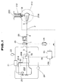
- a drive system of an automotive vehicle with a vehicle body 200 The drive system includes an engine 202 with a throttle 204 which opens by degrees, a transmission 206 operatively coupled with the engine 202, a propeller shaft assembly including a first and a second propeller shafts 1 and 2, a differential 208, and a pair of driving wheels, only one being shown in phantom and designated by 210.
- a rear suspension system 212 is operatively connected between the driving wheels 210 and the vehicle body 200 to support the weight of the vehicle body 200.
- a hydraulic pump 20 provides a hydraulic pressure to a servo valve 23 through an unloading pressure control valve 21 and an accumulator 22.
- a reservoir 24 is interposed between the unloading pressure control valve 21 and the servo valve 23, and an actuator 25 is used for controlling a center bearing supporting position, which is connected to the unloading pressure control valve 21.
- a controller 30 is connected to a position sensor 31 for sensing an amount of compression of a rear suspension, which is a potentiometer in this embodiment, a gear position sensor 32 for sensing a gear position,and a throttle opening sensor 33 for sensing a throttle opening degree of an engine throttle valve, to which controller a position signal P, a gear position signal G, and a throttle opening signal TH are provided respectively.
- the controller 30 is also connected to a servo amplifier 34 which provides a control signal to the servo valve 23 in response to a control signal provided from the controller 30.
- the servo valve 23 hydraulically actuates a movable rod 25a of the actuator 25 in response to the control signal.
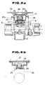
- a propeller shaft portion is described.
- a spring 25b for returning the movable rod 25a is mounted on the actuator 25.
- An upper end portion of the movable rod 25a is associated with a lifting bracket 27 connected to an upper bracket 26 supporting a center bearing 8.
- a mounting flange of a bracket 28 connected to the side of the actuator 25 is fixed on a vehicle body 29.
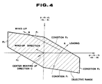
- an admissible angular range for the exciting forces F1, F2,and F3 is set, as shown in Fig. 4, to limit the exciting forces F1, F2,and F3 to predetermined values.
- an objective angular range is set on the exciting forces F1 F2,and F3, so that, when the exciting force F1 acts in a manner to exceed the objective angular range by wind-up during vehicle starting, the exciting force F1 can be kept within the objective angular range by raising the supporting position of the center bearing.
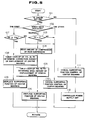
- step 101 it is judged whether an engine key is ON or not. If the engine key is ON, control proceeds to step 102 at which a gear position is checked. If the gear position falls in the neutral, control proceeds step 103. At step 103, it is judged whether the throttle opening degree TH is zero or not. When the throttle opening degree is 0, it is judged that a vehicle is at a standstill. Then, control of steps 104 to 106 is performed (control up to step 106 is achieved from turning-on of the engine key to idling). That is, at step 104, an amount of compression of the rear suspension is read by the position sensor 31 (potentiometer) and, at step 105, a table look-up of a table as shown in Fig.
- a control signal is provided from the controller 30 to the servo valve 23 through the servo amplifier 34 to lift or raise the supporting position of the center bearing by the displacement determined at the step 105.
- the servo valve 23 is ON and the movable rod 25a of the actuator 25 is hydraulically actuated to lift or raise the supporting position of the center bearing.
- Supporting position control of the center bearing of the above steps 101 to 106 is particularly effective when a 3-joint type propeller shaft is mounted on a rigid axle type rear suspension vehicle.
- a 3-joint type propeller shaft is mounted on a rigid axle type rear suspension vehicle.
- an angle of the joint of the propeller shaft is also changed thereby to induce a secondary couple, causing vibration and noise during vehicle starting.
- Such vibration and noise can be reduced by the supporting position control: A positional margin is made in the direction of the wind-up (arrow B) by raising the supporting position of the center bearing (arrow C) as shown in Fig. 4, even if there is increase in loadage (arrow A).
- step 107 at which the throttle opening degree TH is compared with a predetermined value TH0.
- the throttle opening degree TH is equal to or greater than the predetermined value TH0.
- correction during vehicle starting of the supporting position of the center bearing is carried out at steps 108 and 109.
- step 108 in order to determine a correction amount of displacement of a supporting position of the center bearing corresponding to the throttle opening degree TH, a table look-up of a table as shown in Fig. 6b is performed. As shown in the table of Fig. 6b, the greater is the throttle opening degree TH, the greater will be correction amount of displacement of the supporting position.
- step 109 the supporting position of the center bearing is lifted or raised in a similar manner to the above step 106.
- the gear position is other than the neutral or the first gear position at step 102 or if the throttle opening degree TH is not zero at step 103 or if the throttle opening degree TH is less than the predetermined value TH0, the supporting position control of the center bearing is cancelled at step 110, since such control is not necessary when the vehicle is running after the starting operation or when the vehicle is at a standstill with the accelerator depressed.
- the servo valve 23 is OFF and the movable rod 25a of the actuator 25 returns to its initial position due to force of the spring 25b.
- step 101 if it is judged that the engine key is OFF, the supporting position control of the center bearing is cancelled at step 111 and a power supply of the controller 30 is OFF at step 112.
- a propeller shaft assembly is not subject to effect of increase in loadage, so that the position sensor 31 (potentiometer) and supporting position control of steps 103 to 106 may be omitted.
- the throttle opening degree TH used for judgement of step 103 may be replaced by a throttle operating speed V TH .
- a vehicle speed V provided from a vehicle speed sensor or an engine rotation signal N E provided from an engine rotation sensor may be used for judgement whether the vehicle is at a standstill or not.
Landscapes
- Engineering & Computer Science (AREA)
- Chemical & Material Sciences (AREA)
- Combustion & Propulsion (AREA)
- Transportation (AREA)
- Mechanical Engineering (AREA)
- Motor Power Transmission Devices (AREA)
- Vehicle Body Suspensions (AREA)
Claims (10)
einer Antriebswellen-Baugruppe (1, 2), die eine erste Antriebswelle (1) mit einem Ende umfaßt, das mit Antriebsleistungserzeugenden Einrichtungen (206) über ein Gelenk (3) gekoppelt ist, eine zweite Antriebswelle (2) ein Ende aufweist, das mit dem entgegengesetzten Ende der ersten Antriebswelle (1) über ein Gelenk (4) verbunden ist, wobei das entgegengesetzte Ende der zweiten Antriebswelle (2) über ein Gelenk (5) mit einem Differential (208) gekoppelt ist;
Antriebsrädern (210), die funktionsmäßig mit dem Differential (208) gekoppelt sind;
einem Lager (8), das drehbar den Mittelteil der Antriebswellen-Baugruppe (1, 2) trägt; und
einer Trägerstruktur (26-28); die fest mit der Fahrzeugkarosserie verbunden ist und das Lager (8) derart trägt, daß seine Position relativ zur Fahrzeugkarosserie veränderbar ist;
gekennzeichnet durch
Sensoreinrichtungen (31-33), um Betriebsbedingungen abzu- fühlen, denen das Kraftfahrzeug ausgesetzt ist, und um Sensorausgabesignale (P, G, TH) zu erzeugen; und
Einrichtungen (30, 34), um ein Regelsignal als Antwort auf die Sensorausgabesignale zu erzeugen;
die Trägerstruktur (26, 28), einschließlich Einrichtungen (23, 25), die auf das Regelsignal ansprechen um die Position des Lagers (8) relativ zu der Fahrzeugkarosserie zu verändern.
eine Antriebswellen-Baugruppe (1, 2), die eine erste Antriebswelle (1) mit einem Ende, welches über ein Gelenk (3) mit Antriebsleistungserzeugenden-Einrichtungen (206) gekoppelt ist, umfaßt, eine zweite Antriebswelle (2) mit einem Ende, welches mit dem entgegengesetzten Ende der ersten Antriebswelle (1) über eine Gelenk (4) gekoppelt ist, wobei das entgegengesetzte Ende der zweiten Antriebswelle (2) über ein Gelenk (5) mit einem Differential (206) gekoppelt ist;
Antriebsräder (210), die funktionsmäßig mit dem Differential (2-08) gekoppelt sind;
ein Lager (8), das drehbar den Mittelteil der Antriebswellen-Baugruppe trägt; und
eine Trägerstruktur (26-28), die fest mit der Fahrzeugkarosserie verbunden ist und das Lager (8) derart trägt, daß seine Position relativ zu der Fahrzeugkarosserie veränderbar ist, wobei das Verfahren gekennzeichnet ist durch die Schritte:
Abfühlen von Betriebsbedingungen, denen das Kraftfahrzeug ausgesetzt ist, und Erzeugen von entsprechenden Ausgabesignalen;
Erzeugen eines Regelsignals als Antwort auf die Ausgabesignale; und
Verändern der Position des Lagers (8) relativ zu der Fahrzeugkarosserie als Antwort auf das Regelsignal.
Applications Claiming Priority (2)
| Application Number | Priority Date | Filing Date | Title |
|---|---|---|---|
| JP125044/88 | 1988-05-24 | ||
| JP63125044A JPH01297324A (ja) | 1988-05-24 | 1988-05-24 | センタベアリングの支持位置制御装置 |
Publications (2)
| Publication Number | Publication Date |
|---|---|
| EP0343974A1 EP0343974A1 (de) | 1989-11-29 |
| EP0343974B1 true EP0343974B1 (de) | 1992-07-22 |
Family
ID=14900446
Family Applications (1)
| Application Number | Title | Priority Date | Filing Date |
|---|---|---|---|
| EP89305280A Expired EP0343974B1 (de) | 1988-05-24 | 1989-05-24 | Kraftfahrzeug mit veränderlich positionierbarer Lagerung der Antriebswelle |
Country Status (4)
| Country | Link |
|---|---|
| US (1) | US4966251A (de) |
| EP (1) | EP0343974B1 (de) |
| JP (1) | JPH01297324A (de) |
| DE (1) | DE68902182T2 (de) |
Families Citing this family (8)
| Publication number | Priority date | Publication date | Assignee | Title |
|---|---|---|---|---|
| US5703796A (en) * | 1996-07-11 | 1997-12-30 | Ford Global Technologies, Inc. | Driveline alignment apparatus and method |
| US6520678B2 (en) | 2001-03-27 | 2003-02-18 | Spicer Driveshaft, Inc. | Vehicle center bearing assembly including piezo-based device for vibration damping |
| SE0403156L (sv) * | 2004-12-20 | 2006-05-02 | Volvo Lastvagnar Ab | Reglering av drivlinegeometri |
| KR100877780B1 (ko) * | 2007-07-16 | 2009-01-08 | 현대자동차주식회사 | 프로펠러 샤프트 센터베어링 장치 |
| US8851491B2 (en) | 2012-11-30 | 2014-10-07 | Ford Global Technologies, Llc | Mechanically self-powered driveshaft center bearing height adjustment |
| US8646566B1 (en) | 2012-12-14 | 2014-02-11 | Ford Global Technologies, Llc | Remote manual driveshaft center bearing height adjustment mechanisms |
| US9776495B2 (en) * | 2015-12-29 | 2017-10-03 | GM Global Technology Operations LLC | Active mounting system for vehicle transfer case |
| JP2017199401A (ja) * | 2017-06-16 | 2017-11-02 | 日立建機株式会社 | 鉱山用運搬車両 |
Family Cites Families (5)
| Publication number | Priority date | Publication date | Assignee | Title |
|---|---|---|---|---|
| US2776174A (en) * | 1955-02-24 | 1957-01-01 | Ford Motor Co | Motor vehicle driveline mounting |
| US2857974A (en) * | 1956-02-16 | 1958-10-28 | Chrysler Corp | Propeller shaft vibration absorber |
| US2939540A (en) * | 1956-12-10 | 1960-06-07 | Borg Warner | Bearing positioning mechanism for propeller shaft |
| US3175636A (en) * | 1959-10-26 | 1965-03-30 | Chrysler Corp | Curved propeller shaft rotatably supported in a plastic sheath |
| JPS497656B1 (de) * | 1967-06-28 | 1974-02-21 |
-
1988
- 1988-05-24 JP JP63125044A patent/JPH01297324A/ja active Pending
-
1989
- 1989-05-23 US US07/355,658 patent/US4966251A/en not_active Expired - Fee Related
- 1989-05-24 DE DE8989305280T patent/DE68902182T2/de not_active Expired - Fee Related
- 1989-05-24 EP EP89305280A patent/EP0343974B1/de not_active Expired
Also Published As
| Publication number | Publication date |
|---|---|
| US4966251A (en) | 1990-10-30 |
| DE68902182T2 (de) | 1993-01-21 |
| DE68902182D1 (de) | 1992-08-27 |
| JPH01297324A (ja) | 1989-11-30 |
| EP0343974A1 (de) | 1989-11-29 |
Similar Documents
| Publication | Publication Date | Title |
|---|---|---|
| CA1285005C (en) | Control system for motor vehicle suspension unit | |
| CA1222297A (en) | Electronic treadle | |
| US7270335B2 (en) | Electromagnetic suspension apparatus for automotive vehicles and method for controlling electric motor of the same | |
| US7712561B2 (en) | Driving wheel structure for motor vehicle | |
| US5072804A (en) | Power-assisted steering system | |
| US6345680B1 (en) | Electronically-controlled adjustable height bearing support bracket | |
| EP0343974A1 (de) | Kraftfahrzeug mit veränderlich positionierbarer Lagerung der Antriebswelle | |
| EP0253383B1 (de) | Aufhängungssystem vom Typ mit zwei Aufhängungsarmen | |
| JPH0217734B2 (de) | ||
| US12179548B2 (en) | Four bar linkage and air spring suspension system | |
| KR19990037475A (ko) | 산업용 차량의 차축 틸트 제어 방법 및 장치 | |
| CN115519955A (zh) | 悬架系统及其控制方法、车辆 | |
| US11945272B1 (en) | Natural active vehicle suspension assembly | |
| JP2553861B2 (ja) | スタビライザ制御装置 | |
| JPS6082417A (ja) | ハイドロニユ−マチツク懸架装置 | |
| US5180185A (en) | Device for obtaining an axle-load signal of a mechanically spring-supported drive axle of a lifting axle structure | |
| JPH0526525U (ja) | 車両の姿勢制御装置 | |
| JPH0639223B2 (ja) | 自動車用電子制御変速機 | |
| JP2797290B2 (ja) | フロントサスペンション装置のジオメトリー制御装置 | |
| GB2314400A (en) | Engine mounting | |
| JP2020185957A (ja) | 弾性体ブッシュ、サスペンション装置、及び、動力伝達機構の支持構造 | |
| JP3415175B2 (ja) | フォークリフトの制御装置 | |
| JPH06115894A (ja) | 可変容量ポンプ/モータを備えた産業車両の荷役走行制御装置 | |
| KR20030046679A (ko) | 자동차 추진축의 굴절각 조절장치 | |
| JPS63279916A (ja) | スタビライザ制御装置 |
Legal Events
| Date | Code | Title | Description |
|---|---|---|---|
| PUAI | Public reference made under article 153(3) epc to a published international application that has entered the european phase |
Free format text: ORIGINAL CODE: 0009012 |
|
| 17P | Request for examination filed |
Effective date: 19890608 |
|
| AK | Designated contracting states |
Kind code of ref document: A1 Designated state(s): DE GB |
|
| 17Q | First examination report despatched |
Effective date: 19910404 |
|
| GRAA | (expected) grant |
Free format text: ORIGINAL CODE: 0009210 |
|
| AK | Designated contracting states |
Kind code of ref document: B1 Designated state(s): DE GB |
|
| REF | Corresponds to: |
Ref document number: 68902182 Country of ref document: DE Date of ref document: 19920827 |
|
| PG25 | Lapsed in a contracting state [announced via postgrant information from national office to epo] |
Ref country code: GB Effective date: 19930524 |
|
| PLBE | No opposition filed within time limit |
Free format text: ORIGINAL CODE: 0009261 |
|
| STAA | Information on the status of an ep patent application or granted ep patent |
Free format text: STATUS: NO OPPOSITION FILED WITHIN TIME LIMIT |
|
| 26N | No opposition filed | ||
| GBPC | Gb: european patent ceased through non-payment of renewal fee |
Effective date: 19930524 |
|
| PGFP | Annual fee paid to national office [announced via postgrant information from national office to epo] |
Ref country code: DE Payment date: 19940524 Year of fee payment: 6 |
|
| PG25 | Lapsed in a contracting state [announced via postgrant information from national office to epo] |
Ref country code: DE Effective date: 19960201 |