EP0343609A2 - Verfahren zur Herstellung von Druckplatten - Google Patents
Verfahren zur Herstellung von Druckplatten Download PDFInfo
- Publication number
- EP0343609A2 EP0343609A2 EP89109291A EP89109291A EP0343609A2 EP 0343609 A2 EP0343609 A2 EP 0343609A2 EP 89109291 A EP89109291 A EP 89109291A EP 89109291 A EP89109291 A EP 89109291A EP 0343609 A2 EP0343609 A2 EP 0343609A2
- Authority
- EP
- European Patent Office
- Prior art keywords
- pair
- plates
- plate
- pattern
- dry
- Prior art date
- Legal status (The legal status is an assumption and is not a legal conclusion. Google has not performed a legal analysis and makes no representation as to the accuracy of the status listed.)
- Granted
Links
Images


Classifications
-
- G—PHYSICS
- G03—PHOTOGRAPHY; CINEMATOGRAPHY; ANALOGOUS TECHNIQUES USING WAVES OTHER THAN OPTICAL WAVES; ELECTROGRAPHY; HOLOGRAPHY
- G03B—APPARATUS OR ARRANGEMENTS FOR TAKING PHOTOGRAPHS OR FOR PROJECTING OR VIEWING THEM; APPARATUS OR ARRANGEMENTS EMPLOYING ANALOGOUS TECHNIQUES USING WAVES OTHER THAN OPTICAL WAVES; ACCESSORIES THEREFOR
- G03B27/00—Photographic printing apparatus
-
- G—PHYSICS
- G03—PHOTOGRAPHY; CINEMATOGRAPHY; ANALOGOUS TECHNIQUES USING WAVES OTHER THAN OPTICAL WAVES; ELECTROGRAPHY; HOLOGRAPHY
- G03F—PHOTOMECHANICAL PRODUCTION OF TEXTURED OR PATTERNED SURFACES, e.g. FOR PRINTING, FOR PROCESSING OF SEMICONDUCTOR DEVICES; MATERIALS THEREFOR; ORIGINALS THEREFOR; APPARATUS SPECIALLY ADAPTED THEREFOR
- G03F7/00—Photomechanical, e.g. photolithographic, production of textured or patterned surfaces, e.g. printing surfaces; Materials therefor, e.g. comprising photoresists; Apparatus specially adapted therefor
- G03F7/20—Exposure; Apparatus therefor
- G03F7/2022—Multi-step exposure, e.g. hybrid; backside exposure; blanket exposure, e.g. for image reversal; edge exposure, e.g. for edge bead removal; corrective exposure
- G03F7/2032—Simultaneous exposure of the front side and the backside
-
- G—PHYSICS
- G03—PHOTOGRAPHY; CINEMATOGRAPHY; ANALOGOUS TECHNIQUES USING WAVES OTHER THAN OPTICAL WAVES; ELECTROGRAPHY; HOLOGRAPHY
- G03F—PHOTOMECHANICAL PRODUCTION OF TEXTURED OR PATTERNED SURFACES, e.g. FOR PRINTING, FOR PROCESSING OF SEMICONDUCTOR DEVICES; MATERIALS THEREFOR; ORIGINALS THEREFOR; APPARATUS SPECIALLY ADAPTED THEREFOR
- G03F7/00—Photomechanical, e.g. photolithographic, production of textured or patterned surfaces, e.g. printing surfaces; Materials therefor, e.g. comprising photoresists; Apparatus specially adapted therefor
-
- G—PHYSICS
- G03—PHOTOGRAPHY; CINEMATOGRAPHY; ANALOGOUS TECHNIQUES USING WAVES OTHER THAN OPTICAL WAVES; ELECTROGRAPHY; HOLOGRAPHY
- G03F—PHOTOMECHANICAL PRODUCTION OF TEXTURED OR PATTERNED SURFACES, e.g. FOR PRINTING, FOR PROCESSING OF SEMICONDUCTOR DEVICES; MATERIALS THEREFOR; ORIGINALS THEREFOR; APPARATUS SPECIALLY ADAPTED THEREFOR
- G03F9/00—Registration or positioning of originals, masks, frames, photographic sheets or textured or patterned surfaces, e.g. automatically
-
- H—ELECTRICITY
- H01—ELECTRIC ELEMENTS
- H01J—ELECTRIC DISCHARGE TUBES OR DISCHARGE LAMPS
- H01J9/00—Apparatus or processes specially adapted for the manufacture, installation, removal, maintenance of electric discharge tubes, discharge lamps, or parts thereof; Recovery of material from discharge tubes or lamps
- H01J9/02—Manufacture of electrodes or electrode systems
- H01J9/14—Manufacture of electrodes or electrode systems of non-emitting electrodes
- H01J9/142—Manufacture of electrodes or electrode systems of non-emitting electrodes of shadow-masks for colour television tubes
Definitions
- This invention relates to a method of manufacturing main plates for exposure printing, and particularly to a method of manufacturing a pair of main plates for printing a predetermined pattern on photo-sensitive layers respectively formed on both faces of a shadow mask of a color cathode ray tube when the shadow mask is manufactured by a photo-etching method.
- a color cathode ray tube of shadow mask type is provided with a panel having a substantially rectangular face plate and a skirt extending from a peripheral edge of the face plate, a funnel connected to the panel, and a neck continuous to the funnel.
- the panel, funnel and neck holds the interior of the color cathode ray tube in vacuum.
- an electric gun assembly which generates electron beams.
- a deflection yoke which generates magnetic fields is mounted on the outer lateral surfaces of the funnel and the neck.
- a phosphor screen is formed on the inner face of the face plate of the panel.
- a substantially rectangular shadow mask is disposed to be separated from the face plate at a predetermined distance so as to face the phosphor plate.
- the shadow mask is made of a thin metal plate and is formed with a great number of apertures.
- a mask frame surrounds the shadow mask.
- a plurality of elastically deformable mask supports are welded to the frame. Stud pins engaged with the supports are provided on the inner face of the panel.
- the three electron beams emitted from the electron gun assembly are deflected horizontally and vertically by the magnetic field generated by the deflection yoke, and thereafter are converged into apertures of the shadow mask.
- the electron beams converged at the apertures of the shadow mask are landed on the phosphor screen formed on the face plate of the panel.
- the phosphor screen has three kinds of phosphor stripes which are alternately arranged. When these phosphor stripes are shot by the three electron beams passing through the apertures of the shadow mask, these phosphor stripes emit three color lights of red, green and blue.
- the apertures of the shadow mask serve to direct the three beams to the predetermined phosphor stripes which respectively emit red, green and blue lights.
- the shadow mask has a great number of apertures which open at the side of the phosphor screen and at the side of the electron gun.
- the openings of the apertures at the side of the phosphor screen are larger than the openings of the apertures at the side of the electron gun, and the approximately middle portion of the holes has the minimum diameter, such that each aperture has a so-called drum shape.
- the apertures of the shadow mask are formed by the photo-etching method.
- the shadow mask is made of a plate-like shadow mask material of low carbon steel or the like.
- Photo-sensitive layers are formed on both the faces of the shadow mask material.
- a pair of main plates each formed with a pattern corresponding to the apertures of the shadow mask are closely contacted with the respective photo-sensitive layers, and thereafter these layers are exposed to light, whereby the patterns of the main plates are printed on the photo-sensitive layers on both the faces of the shadow mask.
- the unexposed portions are removed from the photo-sensitive layers. Accordingly, resist layers which have patterns corresponding to the patterns of the main plates are formed on the shadow mask material.
- the shadow mask material is etched at its both faces to form apertures which penetrate the shadow mask material.
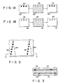
- a pair of main plates will be manufactured as follows:
- Fig. 1A shows a method of manufacturing a main plate to be closely contacted with the face of a shadow mask material at the side of the phosphor screen
- Fig. 1B illustrates how to fabricate a main plate to be closely contacted with the face of the shadow mask material at the side of the electron gun.
- a pattern 24 for etching the face of the shadow mask material at the side of the phosphor screen is drawn by a pattern drawing device on a negative dry plate 22.
- the dry plate 22 is developed to form a first negative pattern plate at the side of the phosphor screen.
- a similar negative dry plate 26 is closely contacted with the first negative pattern plate at the side of the phosphor screen and printed.
- a positive pattern 28 is formed.
- a positive pattern plate having the positive pattern 28 is manufactured which is used as a master.
- a negative dry plate 30 is closely contacted with the positive pattern plate and printed, and the development of the negative dry pattern 30 creates a pattern 32, whereby a second negative pattern plate having the pattern 32 at the side of the phosphor screen is formed which is used as a first main plate for forming the apertures of a shadow mask.
- a pattern 36 for etching the face of the shadow mask material at the side of the electron gun is drawn by the pattern drawing device on a negative dry plate 34 as shown in Fig. 1B.
- the dry plate 34 is developed to form a first negative pattern plate at the side of the electron gun.
- a similar negative dry plate 38 is closely contacted with the first negative pattern plate at the side of the electron gun and printed.
- positive pattern 40 is formed, whereby a positive pattern plate is manufactured which is used as a master.
- a negative dry plate 42 is closely contacted with this positive pattern and printed.
- the dry plate 42 is developed to form a pattern 44, whereby a second negative pattern plate having the pattern 44 at the side of the electron gun is formed which is used as a second main plate for forming the apertures of a shadow mask.
- apertures with a required shape and accuracies can be formed by means of a pair of main plates made by the above-mentioned method. Since, however, with the shadow mask of a color cathode ray tube such as display tube, in which a high resolution is required, the apertures are small and arranged at a small pitch. Accordingly, it is difficult to form apertures with a required shape and accuracies in main plates manufactured by the above method. It is because positional displacement tolerances are small for a pair of main plates.
- the deviation of alignment between those etched concave portions in both the faces of the shadow mask, which are formed from the patterns of the two main plates must be less than 3 microns.
- a factor which causes such displacement between the patterns of a pair of main plates is that a problem exists in the way in which the patterns are described on a first dry plate by a pattern drawing device when the paired main plates are manufactured.
- a pattern drawing device when a pattern drawing device is used, patterns are drawn in the same direction of the order of the rows of the patterns, that is, from the first row to the n'th row (n>1) on a pair of dry plates.
- the patterns of the paired dry plates are drawn similarly in a state inclined from the required angle due to the function and the drawing accuracy of the main pattern drawing device.
- the positional displacement between the upper end and the lower end of the patterns in the outermost n'th row of the shadow mask for a 20-inch color cathode ray tube is 5 to 7 microns.
- Patterns are drawn by the main pattern drawing device on both dry plates with their emulsion faces disposed upward, and thereafter both dry plates are placed on the other dry plates such that their emulsion faces are directed to those of the other dry plates, and the patterns of both the dry plates are transcribed to the other dry plates to form positive pattern plates each having a positive pattern.
- the pattern of the positive pattern plate is also transcribed to further dry plates, thereby manufacturing a pair of main plates.
- Figs. 2 and 3 show a pattern formed on a main plate closely contacted with a shadow mask material when a shadow mask is manufactured.
- the emulsion faces formed with patterns are directed to the photo-sensitive layers of the corresponding faces of a shadow mask material and are closely contacted therewith.
- the first and second main plates are directed to the corresponding faces of the shadow mask material and placed thereon such that the pattern in the first row on the first main plate and the pattern of the last row on the second main plate form, on the shadow mask material, apertures which coincide with each other.
- the object of this invention is to provide a method of manufacturing main plates for exposure printing in which the patterns formed on a pair of main plates can accurately coincide with each other on both the faces of a member to be exposed to light when the patterns are printed on photo-sensitive layers formed on both the faces of the member.
- the method of manufacturing main plates for exposure printing comprises the step of drawing a pattern on each of a pair of original dry plates and developing the pattern on each of the pair of original dry plates, and the step of successively performing transcription of the developed pattern formed on one of the pair of original dry plates even times in such a manner that a transcribed pattern having just formed on a newly supplied dry plate at a prior transcription is now transcribed to a fleshly supplied dry plate at a next transcription, and successively performing transcription of the developed pattern formed on the other one of the pair of original dry plate odd times in such a manner that a transcribed pattern having just formed on a newly supplied dry plate at a prior transcription is now transcribed to a fleshly supplied dry plate at a next transcription, thereby forming a pair of main plates.
- This invention has the technical features that the patterns of a pair of main plates which are closely contacted with both the faces of a member to be exposed to light can be very accurately coincide with each other.
- Fig. 4 shows a color cathode ray tube having a shadow mask.
- the tube 70 is provided with a panel 76 having a substantially rectangular face plate 72 and a skirt 74 extending rearward from the periphery of the face plate 72, a funnel 78 connected to the skirt 74 of the panel 76, and a neck 80 formed continuous to the funnel 78.
- the interior of the color cathode ray tube 70 is held in vacuum by the panel 76, the funnel 78 and the neck 80.
- an electron gun assembly 82 which generates three electron beams.
- a deflection yoke 84 is mounted on the outer surfaces of the funnel 78 and the neck 80.
- a phosphor screen 86 which has three kinds of phosphor layers alternately arranged in a stripe manner.
- the phosphor layers emit red, green or blue light shot by three electron beams, respectively.
- a substantially rectangular shadow mask 88 made of a thin metal plate having a plurality of apertures is disposed opposed to the phosphor screen 86 in the tube 70.
- the shadow mask 88 serves to land the three electron beams from the electron gun assembly 82 on the corresponding phosphor layers.
- a metal mask frame 90 is arranged round the shadow mask 88.
- a plurality of elastically deformable supports 92 are welded to the mask frame 90.
- a plurality of panel pins 94 are arranged on the inner face of the skirt 74.
- the apertures of the shadow mask 88 allot the three electron beams to the predetermined phosphor layers which emit red, green or blue light.
- the shadow mask 88 has a great number of apertures.
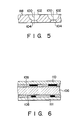
- Fig. 5 shows a longitudinal cross-sectional view including these apertures 100, each of which has an opening 102 at the side of the phosphor screen and another opening 104 at the side of the electron gun.
- the opening 102 at the side of the phosphor screen is larger than the opening 104 at the side of the electron gun, and an approximately middle portion of the aperture 100 has the minimum diameter such that the aperture 100 takes a so-called drum shape. This shape enables the electron beams to be reflected to the inner wall of the aperture 100 to prevent them from being shot to the other areas than the phosphor layers.
- the apertures 100 of the shadow mask 88 are formed by a photo-etching method.
- the shadow mask 88 is made of a plate-like shadow mask material 106 of low carbon steel.
- photo-sensitive layers 108 are formed on both the faces of the shadow mask material 106.
- the layers 108 are closely contacted with a pair of main plates 110 and 111 formed with dot patterns corresponding to the apertures 100 and exposed to light, whereby the patterns of the main plates 110 and 111 are printed on the photo-sensitive layers 108. After developing the photo-sensitive layers 108, the unexposed portions of the photo-sensitive layers 108 are removed.
- resist layers having the patterns corresponding to the patterns of the main plates 110 and 111 are formed on the shadow mask material 106. Thereafter, the apertures 100 penetrating the shadow mask material 106 are opened by etching the material 106 at its both faces.
- a pair of main plates will be manufactured as follows:
- Fig. 7A shows a method of manufacturing a main plates 110 closely contacted with the face of the shadow mask material 106 at the side of the phosphor screen
- Fig. 7B shows how to fabricate a main plate 111 closely contacted with the face of the shadow mask material 106 at the side of the electron gun.
- a dot pattern 114 corresponding to the apertures 100 is drawn on a negative original dry plate 112 by a pattern drawing device (not shown).
- a first negative pattern plate is formed.
- a similar negative dry plate 116 is closely contacted with the first negative pattern plate and printed.
- the dry plate 116 is developed to produce a positive pattern 118 from which a positive pattern plate used as a master is made.
- a negative dry plate 120 is closely contacted with the positive pattern plate and printed.
- a second negative pattern plate having a pattern 122 is formed.
- the second negative pattern plate is formed as the main plate 110.
- a dot pattern 126 corresponding to the apertures 100 is drawn on a negative original dry plate 124 by the pattern drawing device. After developing the dry plate 124, a negative pattern plate is formed. A positive dry plate 128 is closely contacted at its emulsion face with the negative pattern plate. After developing the dry plate 128, a negative pattern 130 is printed to form a positive pattern plate having the negative pattern 130, which is used as the main plate 111.
- the apertures 100 can be formed which has a shape and accuracies required for the shadow mask 88.
- the shadow mask of a color cathode ray tube such as a display tube, which requires a high resolution has small apertures arranged at a small pitch.
- the displacement tolerance S between the pattern 122 and the pattern 130 is small.
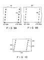
- the dry plates 112 and 124 on which patterns are drawn by the pattern drawing device are shown in Figs. 9A and 9B, respectively. Patterns are drawn in turn in the same direction of the order of the rows of the patterns, that is, from the first order to the n'th order (n>1).
- the patterns 112 and 114 of the paired main plates 110 and 111 are similarly inclined.
- the paired main plates 110 and 111 are used for printing a shadow mask, the emulsion faces in which the patterns are to be formed are closely contacted with the photo-sensitive layers on both the faces of the shadow mask material 106.
- Fig. 10 shows a shadow mask material 106, the pattern 120 of a main plate 110 and the pattern 130 of a main plate 111.
- the main plates are disposed to face each other such that the apertures in the first row on the main plate 110 coincide with the apertures in the first row on the main plate 111. If the rows of the patterns to be formed on the shadow mask material are inclined from the required angle, the inclinations of the rows of the two patterns are same, because the patterns face each other on the respective faces of the shadow mask material. As a result, the positional displacement between the paired etched concave portions formed in both the faces of the shadow mask material is remarkably reduced.
- the pattern displacement was less than 3 microns over the whole area of the shadow mask.
- the diameter of the dot of the pattern of the main plate was 0.130 mm
- the diameter of the dot of the pattern of the main plate 111 was 0.06 mm
- the pitch of the dot of the patterns was 0.250 mm.
- a negative plate having a positive pattern can be made for finding inequality of the patterns.
- a negative dry plate is closely contacted with either the dry plate 124 or the dry plate 128 and then printed, thereby forming the pattern plate having the positive pattern.
- this pattern plate small deviation of the pattern dimensions and the irregularity of the pattern can be easily detected.
- the pattern on the main plate 110 bears the aperture images corresponding to the larger apertures at the side of the phosphor screen and the pattern on the other main plate 111 bears the aperture images corresponding to the smaller apertures at the side of the electron gun.
- the scope of this invention is not limited to this arrangement, but the diameters of the aperture images at the side of the phosphor screen and at the side of the electron gun can be reversed.
- This method of the invention is not limited to a method of manufacturing main plates for a shadow mask of a color cathode tube, but is applicable to a method of manufacturing a pair of main plates disposed opposite to or closely contacted with photo-sensitive layers formed on both faces of the other kind of plate-like member to be exposed to light.
- the apertures of a shadow mask are accurately arranged and regularly shaped. This enhances the resolution of a color cathode ray tube having this shadow mask.
Landscapes
- Physics & Mathematics (AREA)
- General Physics & Mathematics (AREA)
- Engineering & Computer Science (AREA)
- Manufacturing & Machinery (AREA)
- Preparing Plates And Mask In Photomechanical Process (AREA)
- Exposure And Positioning Against Photoresist Photosensitive Materials (AREA)
Applications Claiming Priority (2)
| Application Number | Priority Date | Filing Date | Title |
|---|---|---|---|
| JP12491188A JP2703262B2 (ja) | 1988-05-24 | 1988-05-24 | 露光焼付け用原版の製作法 |
| JP124911/88 | 1988-05-24 |
Publications (3)
| Publication Number | Publication Date |
|---|---|
| EP0343609A2 true EP0343609A2 (de) | 1989-11-29 |
| EP0343609A3 EP0343609A3 (de) | 1991-07-17 |
| EP0343609B1 EP0343609B1 (de) | 1995-08-30 |
Family
ID=14897165
Family Applications (1)
| Application Number | Title | Priority Date | Filing Date |
|---|---|---|---|
| EP89109291A Expired - Lifetime EP0343609B1 (de) | 1988-05-24 | 1989-05-23 | Verfahren zur Herstellung von Druckplatten |
Country Status (5)
| Country | Link |
|---|---|
| EP (1) | EP0343609B1 (de) |
| JP (1) | JP2703262B2 (de) |
| KR (1) | KR940001951B1 (de) |
| CN (1) | CN1028916C (de) |
| DE (1) | DE68923994T2 (de) |
Family Cites Families (1)
| Publication number | Priority date | Publication date | Assignee | Title |
|---|---|---|---|---|
| US3973964A (en) * | 1974-12-23 | 1976-08-10 | Zenith Radio Corporation | Method for manufacturing a color cathode ray tube and for making screening and mask masters used therein |
-
1988
- 1988-05-24 JP JP12491188A patent/JP2703262B2/ja not_active Expired - Fee Related
-
1989
- 1989-04-24 CN CN89102822A patent/CN1028916C/zh not_active Expired - Fee Related
- 1989-05-23 KR KR1019890006947A patent/KR940001951B1/ko not_active Expired - Fee Related
- 1989-05-23 EP EP89109291A patent/EP0343609B1/de not_active Expired - Lifetime
- 1989-05-23 DE DE68923994T patent/DE68923994T2/de not_active Expired - Fee Related
Also Published As
| Publication number | Publication date |
|---|---|
| KR890017573A (ko) | 1989-12-16 |
| JP2703262B2 (ja) | 1998-01-26 |
| DE68923994T2 (de) | 1996-02-01 |
| CN1028916C (zh) | 1995-06-14 |
| KR940001951B1 (ko) | 1994-03-12 |
| CN1038357A (zh) | 1989-12-27 |
| EP0343609B1 (de) | 1995-08-30 |
| JPH01295260A (ja) | 1989-11-28 |
| DE68923994D1 (de) | 1995-10-05 |
| EP0343609A3 (de) | 1991-07-17 |
Similar Documents
| Publication | Publication Date | Title |
|---|---|---|
| US3766419A (en) | Cathode-ray tube with shadow mask having random web distribution | |
| US4618801A (en) | Flat cathode ray tube | |
| US3947718A (en) | Shadow mask having elongated apertures concave to vertical center line and increasing in pitch along x-axis with distance from said line | |
| KR0154550B1 (ko) | 칼라음극선관 및 그 제조방법 | |
| US3973965A (en) | Making shadow mask with slit-shaped apertures for CRT | |
| CN1065981C (zh) | 有增强分辨率的荫罩的制造方法 | |
| US3882347A (en) | Color stripe cathode ray tube having bridged strip apertures | |
| KR100310404B1 (ko) | 컬러음극선관용섀도우마스크및그의제조방법 | |
| US5336587A (en) | Method of manufacturing main plates for exposure printing | |
| US6491831B1 (en) | Method of making a shadow mask for a cathode ray tube | |
| EP0343609B1 (de) | Verfahren zur Herstellung von Druckplatten | |
| KR930007362B1 (ko) | 칼라 표시관 | |
| US3922577A (en) | Channel plate electron multiplier adjacent color dot screen | |
| US6421507B1 (en) | Method of producing a screen for a display device, screen for a display device produced by means of said method and display device provided with said screen | |
| US4339516A (en) | Method of manufacturing reproduction masks for producing a pattern of elongate apertures in a shadow mask of a color cathode ray tube | |
| US2947898A (en) | Color picture tube screen | |
| JP3474271B2 (ja) | カラーブラウン管用シャドウマスクおよびその製造方法 | |
| US2947627A (en) | Forming patterned phosphor screens in post acceleration cathode ray tubes | |
| US3988632A (en) | Black-surround color picture tube | |
| KR100365524B1 (ko) | 비관통선을 가지는 새도우 마스크 및 이의 제조방법 | |
| JPH0757623A (ja) | カラー受像管の製造方法 | |
| JPH11297225A (ja) | カラー受像管およびその製造方法 | |
| EP0400565A2 (de) | Projektionskathodenstrahlröhre | |
| GB2176647A (en) | Manufacture of colour CRT phosphor screens | |
| KR100308233B1 (ko) | 음극선관노광장치의광량보정필터 |
Legal Events
| Date | Code | Title | Description |
|---|---|---|---|
| PUAI | Public reference made under article 153(3) epc to a published international application that has entered the european phase |
Free format text: ORIGINAL CODE: 0009012 |
|
| 17P | Request for examination filed |
Effective date: 19890620 |
|
| AK | Designated contracting states |
Kind code of ref document: A2 Designated state(s): DE FR GB |
|
| PUAL | Search report despatched |
Free format text: ORIGINAL CODE: 0009013 |
|
| AK | Designated contracting states |
Kind code of ref document: A3 Designated state(s): DE FR GB |
|
| 17Q | First examination report despatched |
Effective date: 19940520 |
|
| GRAA | (expected) grant |
Free format text: ORIGINAL CODE: 0009210 |
|
| AK | Designated contracting states |
Kind code of ref document: B1 Designated state(s): DE FR GB |
|
| REF | Corresponds to: |
Ref document number: 68923994 Country of ref document: DE Date of ref document: 19951005 |
|
| ET | Fr: translation filed | ||
| PLBE | No opposition filed within time limit |
Free format text: ORIGINAL CODE: 0009261 |
|
| STAA | Information on the status of an ep patent application or granted ep patent |
Free format text: STATUS: NO OPPOSITION FILED WITHIN TIME LIMIT |
|
| 26N | No opposition filed | ||
| REG | Reference to a national code |
Ref country code: GB Ref legal event code: 746 Effective date: 19981012 |
|
| REG | Reference to a national code |
Ref country code: FR Ref legal event code: D6 |
|
| REG | Reference to a national code |
Ref country code: GB Ref legal event code: IF02 |
|
| PGFP | Annual fee paid to national office [announced via postgrant information from national office to epo] |
Ref country code: DE Payment date: 20070517 Year of fee payment: 19 |
|
| PGFP | Annual fee paid to national office [announced via postgrant information from national office to epo] |
Ref country code: GB Payment date: 20070523 Year of fee payment: 19 |
|
| PGFP | Annual fee paid to national office [announced via postgrant information from national office to epo] |
Ref country code: FR Payment date: 20070510 Year of fee payment: 19 |
|
| GBPC | Gb: european patent ceased through non-payment of renewal fee |
Effective date: 20080523 |
|
| REG | Reference to a national code |
Ref country code: FR Ref legal event code: ST Effective date: 20090119 |
|
| PG25 | Lapsed in a contracting state [announced via postgrant information from national office to epo] |
Ref country code: FR Free format text: LAPSE BECAUSE OF NON-PAYMENT OF DUE FEES Effective date: 20080602 Ref country code: DE Free format text: LAPSE BECAUSE OF NON-PAYMENT OF DUE FEES Effective date: 20081202 |
|
| PG25 | Lapsed in a contracting state [announced via postgrant information from national office to epo] |
Ref country code: GB Free format text: LAPSE BECAUSE OF NON-PAYMENT OF DUE FEES Effective date: 20080523 |