EP0343063B1 - Winde zum Antreiben eines Bandes - Google Patents
Winde zum Antreiben eines Bandes Download PDFInfo
- Publication number
- EP0343063B1 EP0343063B1 EP19890401356 EP89401356A EP0343063B1 EP 0343063 B1 EP0343063 B1 EP 0343063B1 EP 19890401356 EP19890401356 EP 19890401356 EP 89401356 A EP89401356 A EP 89401356A EP 0343063 B1 EP0343063 B1 EP 0343063B1
- Authority
- EP
- European Patent Office
- Prior art keywords
- pulley
- profile
- belt
- rollers
- flat
- Prior art date
- Legal status (The legal status is an assumption and is not a legal conclusion. Google has not performed a legal analysis and makes no representation as to the accuracy of the status listed.)
- Expired - Lifetime
Links
- 230000002093 peripheral effect Effects 0.000 claims description 35
- 238000004804 winding Methods 0.000 claims description 15
- 230000000694 effects Effects 0.000 claims description 8
- 230000002035 prolonged effect Effects 0.000 claims 1
- 230000001105 regulatory effect Effects 0.000 claims 1
- 230000000284 resting effect Effects 0.000 description 4
- 230000000295 complement effect Effects 0.000 description 3
- 230000006835 compression Effects 0.000 description 2
- 238000007906 compression Methods 0.000 description 2
- 239000013013 elastic material Substances 0.000 description 2
- 238000003780 insertion Methods 0.000 description 2
- 230000037431 insertion Effects 0.000 description 2
- 229920002994 synthetic fiber Polymers 0.000 description 2
- 238000012549 training Methods 0.000 description 2
- 240000008042 Zea mays Species 0.000 description 1
- 238000007792 addition Methods 0.000 description 1
- 230000005540 biological transmission Effects 0.000 description 1
- 230000015572 biosynthetic process Effects 0.000 description 1
- 230000005489 elastic deformation Effects 0.000 description 1
- 239000000463 material Substances 0.000 description 1
- 239000002184 metal Substances 0.000 description 1
- 238000000034 method Methods 0.000 description 1
- 238000012986 modification Methods 0.000 description 1
- 230000004048 modification Effects 0.000 description 1
- 210000000056 organ Anatomy 0.000 description 1
- 125000006850 spacer group Chemical group 0.000 description 1
- 239000000126 substance Substances 0.000 description 1
- 230000001629 suppression Effects 0.000 description 1
- 238000013022 venting Methods 0.000 description 1
Images


Classifications
-
- B—PERFORMING OPERATIONS; TRANSPORTING
- B66—HOISTING; LIFTING; HAULING
- B66D—CAPSTANS; WINCHES; TACKLES, e.g. PULLEY BLOCKS; HOISTS
- B66D1/00—Rope, cable, or chain winding mechanisms; Capstans
- B66D1/60—Rope, cable, or chain winding mechanisms; Capstans adapted for special purposes
- B66D1/74—Capstans
- B66D1/7415—Friction drives, e.g. pulleys, having a cable winding angle of less than 360 degrees
Definitions
- the present invention relates to an apparatus for driving a flat flexible link, such as a strap or a belt, to which a load is attached.
- Apparatuses comprising a drive pulley device, moved manually or mechanically, which scrolls a cable without storing it.
- this device the tightening of the cable in the groove of the pulley is exerted by the pressure of a pivoting member, a roller or a series of rollers for example, this pressure being applied either by the effect of springs, or by the effect of deflection exerted by the load.
- a pivoting member a roller or a series of rollers for example, this pressure being applied either by the effect of springs, or by the effect of deflection exerted by the load.
- patent FR-A-1 389 136 describes a traction device allowing the lifting and lowering of a load.
- This device comprises a pulley driven in rotation, a cable which runs on the periphery of this pulley and to one strand of which the load is fixed, and a chain of pressure rollers which is constrained, under the effect of the load, to press the cable on the peripheral surface of the pulley.
- the peripheral groove of the pulley has a cross section in V to receive the cable which is pressed by the rollers of the chain.
- the object of the present invention is to remedy to this drawback and proposes for this purpose a drive device which is constituted by the combination of a pulley, clamping and guiding members, and a flexible flat link to which the load, the pulley and the clamping and guiding members being designed to allow the driving of such a flexible flat link, strap or flat belt for example, taking into account the constraints specific to the use of such a link, constraints different from those encountered for driving a round section link, such as a cable, in particular less flexible than a flat link and, in particular, a strap.
- the invention applies to the different possible embodiments of known devices, according to the two main methods of tightening the cable in the pulley groove, that is to say constant pressure by springs and pressure by return of a deflection of the load.
- the pressure of the flexible link against the peripheral surface of the pulley can be applied by a single pressing member or by a series of pressing members arranged at the periphery of the pulley.
- these can be actuated either by separate springs applied respectively to each of them, or by a force applied at a single point, itself transmitted to said pressing members or by a bogie system , or by a connection between said pressing members by means of a series of links forming a chain with these pressing members.
- a separate spring or springs for each pressing member can be combined with a deflection action, said spring or said springs then playing a permanent pre-tightening role.
- the action of the springs can be replaced by an elastic deformation of the surface peripheral of the pulley and / or of a pressing member whose axis is then fixed.
- means can be provided for retracting the axis of the pressing member during the introduction of the flexible link.
- said chain is subjected to tensile stress, at its end situated on the side of the soft strand of the link, from a deflection member disposed on the path of the strand charged with the link, and in a direction forming an angle at most of 90 ° with the radius of the pulley passing through the end point of said chain to which this traction applies.
- the arrangement of the pressing member or pressing members is arranged so that the winding arc of the link on the pulley covers the greatest possible radial angle.
- the drive system can also be designed for winding the link along an S-shaped path around two pulleys, the pulley of which is located downstream from the load and is fitted with the pressure and guidance devices mentioned above.
- the device for driving a load comprises a pulley driven in rotation, a flexible link running on the periphery of said pulley and to one strand of which the load is fixed, and constrained means for pressing the link on the peripheral surface of the pulley, said means being mainly constituted by at least one roller and the peripheral surface of the pulley being profiled to receive the winding of such a link by cooperating with a counter-profile, and it is characterized in that the link is flat and in that the counter-profile corresponds to the profile of the peripheral surface of the pulley and belongs to the peripheral surface of the pressure roller (s).
- the peripheral profile of the pulley can thus be flat with lateral guide flanges, or concave in an elliptical shape or a very flat V shape with a flat bottom or bottom formed by an arc tangent to the two branches of the V, or conversely be convex in one of the forms mentioned above for the concave profile.
- the peripheral profile of the pressure member (s) being the counter-profile which corresponds to the peripheral profile of the pulley, so as to ensure correct cooperation of the pulley, the flat link and the pressing member.
- peripheral surfaces of the pulley and / or of the pressing member (s) may be coated with a substance chosen to improve their adhesion to one and / or the other of the two flat surfaces of the link, depending on the material of which it is made. this. Furthermore, the peripheral surface of the pulley and / or of the pressing member or of the pressing members may include a system of roughness such as knurling.
- the configuration and flexibility of the flat link require the fitting of appropriate guiding means in order to ensure a course correct soft strand of this link during the upward movement or traction of the load, and especially in order to avoid its untimely winding around the pulley training outside its normal course. Similarly on the side of the strand loaded with the link, if the load ceases to apply to it.
- the invention provides a guide which covers the peripheral part of the pulley not covered by the winding of the flexible link, at least on the side where the soft strand must leave the peripheral surface of the pulley, so that the strand leaving this surface is thus deviated out of the circular path that the pulley tends, by its movement, to impress on it.
- the guide has a curved face conforming to the shape of the periphery of the pulley on its part not covered by the winding of the link and extending from one point to the other of the two points of insertion of the link. on the pulley.
- the curved face of the guide can be extended, at each of its ends, by a lateral face arranged to orient the movement of the link so as to print the desired path inside the device.
- a fourth face can join the ends of the two preceding ones according to an appropriate conformation, and the guide thus formed can be constituted either by a full or partially full piece, or by a plate folded in a suitable way.
- the guide can be held in place in a position of extreme proximity to the pulley arch that it covers, and it then has a curvature concentric with that of the pulley.
- the guide can also be applied in contact with the pulley, by a spring acting on the face of the guide located opposite the pulley and whose action can be adjusted.
- the curvature of this face is of a radius substantially less than that of the pulley, so that only its two ends are in frictional contact with the pulley.
- Complementary devices can guide the movement of the guide under the effect adjustment of the above spring, this adjustment being able, if necessary, to remove the contact between the guide and the pulley.
- the face of the guide located opposite the pulley can be made of an elastic material ensuring flexibility of this face under the action of the spring mentioned above.
- a pair of rollers whose axes are parallel to that of the pulley, can be associated, outside the pulley, with the soft strand of the link as well as, optionally , to the load carrying strand in case it ceases to apply to this strand.
- Each of these pairs can be completed by a pair of rollers located in their vicinity, whose axes are perpendicular to those of each pair above, so as to frame the faces of the flat link delimiting the thickness thereof.
- a simplified embodiment of this device only one of the rollers of the pair or pairs of rollers concerned is thus motorized, while the other roller is applied against the link by an adequate pressure means, so as to maintain contact constant between the link and the motorized roller.
- the soft strand of the link can be recovered by a winding system incorporated in the device and provided with a spring system which constantly urges it in the winding direction, regardless of the direction of rotation of said winding system.
- this arrangement does not make it possible to maintain the tension of the strand loaded in the event of the suppression of the application of the load in the direction of descent.
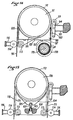
- FIG. 1 and 2 there is shown an apparatus comprising a pulley 1 fixed in its center on a drive shaft 2.
- the peripheral part 3 of the pulley 1 is made of a synthetic material with high coefficient of friction and present towards the outside a flat profile on which a strap 4 is applied.
- the strap 4 cooperates with the pulley 1 over the major part of the peripheral part 3 of the latter and, to one of its strands 5 is coupled the load (not shown in the drawing) to haul or haul, while its other strand 6 is free.
- the tightening of the strap 4 on the periphery of the pulley 1 is ensured by means of a pressure roller 7 mounted idly at one end of a lever 8 whose other end is pivotally mounted around a fixed point 9.
- a compression spring 1O resting on a fixed structural element 11, applies the pressure roller 7 against the periphery of the pulley by tightening the strap 4 on the side of the free strand 6 thereof.
- the profile of the pressure roller 7 corresponds to that of the periphery of the pulley 1, that is to say is flat to ensure the tightening of the strap 4 over the entire transverse part of that -this.
- the arrangement of the lever 8 is chosen so that the part of the periphery of the pulley 1 with which cooperates the strap 4 is as large as possible in order to optimize the adhesion of the strap on the pulley.
- FIG. 3 there is shown another embodiment of the apparatus according to the invention, according to which the tightening of the strap 14 on the periphery of the pulley 12, fixed on the shaft 13, is provided by a plurality of independent rollers 24 arranged all around the pulley in radial directions.
- Each roller 24 is mounted idly on a yoke 25 constrained by a spring 26, resting on a casing 27, in the direction of the pulley.
- the load can be applied indifferently to one or the other of the two strands 15, 16 of the strap 14.
- a winch comprising a drive shaft 31 which passes through the central opening 32 of a yoke 33 consisting of two flanges 34,35 assembled one to the other by means of bolts 36 and spacers 37.
- a pulley 38 On the shaft 31 is fixed a pulley 38 whose periphery 39 is made of a synthetic material with a high coefficient of friction.
- the peripheral part 39 of the pulley 38 Towards the outside, the peripheral part 39 of the pulley 38 has in section a very open V-shaped profile designed for good cooperation with the intermediate part of a strap 40 which is wound around the pulley.
- the load (not shown in the drawing) to haul or to haul, while the other strand 42 of the strap is free.
- the tightening of the strap 40 on the periphery of the pulley 38 is ensured by a link chain consisting of a succession of links 43 interconnected by axes 44, each axis 44 carrying a roller 45 having a V-shaped profile combined with that of the peripheral part 39 of the pulley 38.
- a terminal link 43 ′ disposed on the side of the loaded strand 41 of the strap, is fixed to the yoke of the pulley by means of an axis 46.
- On this axis 46 is articulated one end of a link 47 whose end opposite carries the axis of a deflector roller 48 over which the loaded strand 41 of the strap passes.
- the other end link 43 "of the chain is connected by its axis 44" to one end of a connecting rod 49 whose opposite end is articulated on an axis 5O secured to the yoke.
- the connecting rod 49 has axially a plurality of openings 51 allowing selectively, by means of an axis 52, the adjustable articulated fixing of one end of a connecting rod 53 whose other end is articulated on the axis of the roller deflector 48.
- the successive links 57 constituting the chain are interconnected by axes 58 each carrying a pressure roller 59.
- the axis 58 ′ carrying the last pressure roller 59 ′ is connected to a fixed point .
- the position of the latter is determined so as to maintain at least the roller 59 ′ in contact with the strap 54.
- the last link 57 is connected to the axis of the roller 61 mounted at the end of a lever 62 pivoting about a fixed axis 63.
- a spring 64 resting on a fixed point 65 constrains the lever 62 towards its position pressing the chain against the periphery of the pulley.
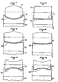
- Figure 7 there is shown the periphery 69 of the pulley 68 of an apparatus according to the invention, with a concave curvature groove 71 of elliptical shape, the pressure roller 72 tightening the strap 7O in the groove having an exactly complementary profile .
- the concave shape of the groove profile can of course be different, for example circular.
- the profile shown of the groove of the pulley 73 has a flat bottom 74 receiving the roller 75.
- the profile of the periphery 76 of the pulley 77 has the shape of a V with a large opening 78 the bottom of which is constituted by an arc tangent to the two branches of the V.
- the profile of the groove of the pulley 79 has the shape of a V with a large opening 8O, the bottom of which is flat.
- the groove profile 81 of the pulley 82 has a circular convex shape, but it is understood that this convex shape could be elliptical.
- the groove profile 83 of the pulley 84 has a convex inverted V shape with a very large opening, the top of which is flattened. It is understood, however, that the top could be tapered or even arched.
- the deflection guide 98 is constituted by a folded metal plate having an arcuate upper face 99 of the same radius of curvature as that of the pulley 91.
- the face 99 of the guide 98 is intended to follow the shape of the periphery of the pulley 91 on its part not covered by the winding of the strap 92 and extends from one to the other of the two points of insertion of the strap 92 on the pulley.
- Two side faces 1OO extend the arcuate face 99 and each guide the desired path of the strap 92 inside the device.
- the ends of the faces 1OO are joined by a lower face 1O1 resting on the supports 1O2 secured to the casing of the apparatus, so that the arched face 99 is held in place in the position of extreme proximity to the arch of the pulley 91 that it covers.
- FIG 15 there is shown a variant of the apparatus of Figure 14 with a different deflection device 1O4 comprising an arcuate face 1O5 made of an elastic material and which has a radius of curvature substantially less than that of the pulley 1O6.
- the ends of the arcuate face 1O5 are applied in friction to the periphery of the pulley 1O6 under the action of a spring 1O7 acting in the direction of the axis of symmetry of the face 1O5.
- the spring 10 7 rests on a fixed point 10 8 secured to the casing of the device by means of a device 10 9 which makes it possible to locate and adjust the compression of the spring.
- the loaded strand 110 and the soft strand 111 of the strap 112 each pass between two rollers 113,114 with axes parallel to the axis of the pulley 1O6.
- the rollers 113 are driven in rotation, by the pulley 1O6, by means of a belt 115, with a peripheral linear speed of rotation which is equal to the linear speed imparted by the pulley 1O6 to the strap 112.
- the rollers 114 are at free rotation and press the strap 112 against the rollers 113 under the action of springs 116.
- the strand of the strap 112 exiting the pulley 1O6 is driven by the rollers 113,114 at the same speed of rotation as that of the pulley 1O6, which prevents the accidental formation of a loop of this strand capable of being able to engage between the pulley and the strand of the strap 112 returning thereto.
- the roller system 113,114 is replaced, on the side of the soft strand 97 of the strap 92, by a winding drum 118 of this strand 97 provided with a spring 119 urging it constantly in the direction of winding (direction of arrow A) whatever the direction of rotation of the drum 118.
- each pair of rollers 113,114 is associated with a pair of rollers 120, 121 oriented perpendicularly to these to frame the strap and mounted in free rotation.
- the association of motorized rollers 113,114 and rollers 12O, 121 applies a tension on the strap strand with which these rollers cooperate, making it possible to prevent the strap strand from coming into wedge because of its flexibility.
Landscapes
- Engineering & Computer Science (AREA)
- Mechanical Engineering (AREA)
- Devices For Conveying Motion By Means Of Endless Flexible Members (AREA)
- Basic Packing Technique (AREA)
Claims (11)
- Vorrichtung zum Mitnehem einer Last, bestehend aus einer unetr Drehung angetriebenen Antriebsscheibe (1, 12, 38, 91, 106), einem um dem Umfang der Antriebsscheibe umlaufenden elastichen Band (4, 14, 40, 54, 70, 92, 112), an dessen Trum die Last befestigt ist, sowie aus einer Einrichtung (4, 14, 40, 54, 70, 92, 112), die zum Andrücken des Bandes (4, 14, 40, 54, 70, 92, 112) gegen die Umfangsfläche der Antriebsscheibe angesteurt wird, wobei die Einrichtung in erster Linie aus mindestens einer Rolle (7, 24, 45, 59, 72, 93) gebildet ist und die Umfangsfläche der Antriebsscheibe (1, 12, 38, 91, 106) ein Profil zum Aufnehem eines solchen abalufenden Bandes im zusammenwirken mit einem Gegenprofil aufweist,
dadurch gekennzeichnet,
daß das Band (4, 14, 40,54, 70, 92, 112) flach ist und daß das Gegenprofil dem Profil der Umfangsfläche der Antriebsscheibe entspricht und der Umfangsfläche der Andruckrolle(n) (7, 24, 45, 59, 72, 93) zugeordnet ist. - Vorrichtung nach Anspruch 1,
dadurch gekennzeichnet,
die Umfangsfläche der Antriebsscheibe (73) ein Profil (74) aufweist, welches die Zentrierung des flachen Bandes (70) bei dessen Ablauf gegenüber der Mittelebene gewährleistet, wobei das Profil (74) flach ausgebildet und von Flanschen begrenzt ist, während das Umfangsprofil des Andruckelements (75) ebenfalls flach ist. - Vorrichtung nach Anspruch 1,
dadurch gekennzeichnet,
daß die Umfangsfläche (39, 69, 76) der Antriebsschiebe (38, 68, 77, 79) ein Profil aufweist, welches die Zentrierung des flachen Bandes (40, 70) bei dessen Ablauf gegenüber der Mittelebene gawährleistet, wobei das Profil (71, 78, 80) konkav und elliptisch bzw. stark abgeflacht V-förmig ist und gegebenenfalls einen flachen Boden bzw. einen Boden aufweist, der von einem die beiden v-Schenkel tangierende Bogen gebildet wird, und wobei das Umfangsprofil des Andruckelements (45, 72) das dem Umfangsprofil der Antriebsscheibe entsprechende Gegenprofil darstellt. - Vorrichtung nach Anspruch 1,
dadurch gekennzeichnet,
daß die Umfangsfläche der Antriebsscheibe (82, 84) ein Profil aufweist, das die Zentreirung des flachen Bandes (70) bei dessen Ablauf gegenüber der Mittelebene gewährleistet, wobei das Profil (81, 83) konvex und elliptisch bzw. stark abgeflacht v-förmig ist und gegebenenfalls einen flachen Boden bzw. einen Boden aufwesit, der von einem die beiden V-Schenkel tangierenden Bogen gebildet wird, und wobei das Umfangsprofil des Andruckelements (45, 72) das dem Umfangsprofil der Antriebsscheibe entsprechende Gegenprofil darstellt. - Vorrichtung nach einem der vorhergehenden Ansprüche,
gekennzeicnet durch
eine Umlenkführung (98, 106), welche der Antriebsscheibe (91, 106) zwischen den beiden Punkten, an denen das flache elastiche Band (92, 112) mit der Antriebsschiebe in deren Drehrichtung in Berührung kommt und außer Berührung mit dieser gebracht wird, zugeordnet ist, wobei die Umlenkführung das von der Antriebsschiebe auf deren Kreisbahn ablaufende Baudtrum durch seine Bewegung so angetrieben ist, daß sie in dieses eindrückt. - Vorrichtung nach Anspruch 5,
dadurch gekennzeichnet,
daß die Umlenkfürung (98) eine gebogene Fläche (102) aufweist, die gegenüber dem Bogenabschnitt der Reimenschiebe (91) in äußerster Nähe zu diesem angeordnet ist, auf welchen der zulauf des von der Antriebsschiebe ablaufenden Trums des flachen elastichen Bandes (92) verhindert ist, wobei die gebogene Fläche (102) konzentrisch zum Bogen der Antriebsschiebe ist. - Vorrichtung nach Anspruch 5,
dadurch gekennzeichnet,
daß die Umlenkfürung (104) eine gebogene Fläche (105) aufweist, die gegenüber dem Bogenabschnitt der Riemenscheibe (106) in äßerster Nähe zu diesem angeordnet ist, auf welchen der Zulauf des von der Antriebsschiebe ablaufenden Trums des flachen elastichen Bandes (112) verhindert ist, wobei der Krümmungsradius der Fläche (105) wesentlich kleiner als der Krümmungsradius der Antriebsscheibe ist und ihre beiden äußeren Enden unter Reibungsschluß in Anlage gegen den Umfang der Antriebsscheibe sind, gegebenenfalls an einer zum Mittelpunkt der Antriebsscheibe unter Einwirkung einer Feder (107) verlagerbaren Position, wobei die Position auf weniger oder stärkeren Reibungsscluß bzw. so einstellbar ist, daß die Berührung zwischen den beiden Enden der Fläche (105) und dem Umfang der Antriebsscheibe aufhebbar ist. - Vorrichtung nach Anspruch 6,
dadurch gekennzeichnet,
daß sich die gebogene Fläche (102) der Umlenkführung (98) an jedem ihrer Enden in einer Seitenfläche (100) unter Einhaltung einer Anordnung fortsetzt, die den Ablauf des Bandtrums (92) zu einer Austrittsöffnung aus dem Gehäuse der Vorrichtung ausrichtet. - Vorrichtung nach einem der Ansprüche 1 bis 8,
dadurch gekennzeichnet,
daß ein Paar beiderseits des flachen Bandes (92, 112) zwischen der Antriebsscheibe (91, 106) und der Geräteöffnung zumindest auf der Seite des spannungslosen Trums angeordnete rollen (113, 114), deren Achsen parallel zur Achse der Antriebsscheibe sind, in fortlaufendem Kontakt mit jeder der flachen Seiten des Bandes so angelegt ist, daß sie dessen Bewegung folgen, wobei die eine Rolle (114) hierzu von einer Feder (116) gegen das Trum angedrückt wird und die ander Rolle (113) mit gleicher Umfangsgeschwindigkeit wie die Antriebsscheibe antrieben wird. - Vorrichtung nach Anspruch 9,
dadurch gekennzeichnet,
daß das Paar bzw. die Paare Rollen (113, 114) von einem Paar Rollen (120, 121) ergänzt wird bzw. werden, das in seiner bzw. ihrer Nähe angeordnet ist, wobei die Achsen der Rollen senkrecht zu den Achsen der ersten Rollen so verlaufen, daß das betreffende Trum allseitig eingeschlossen wird. - Vorrichtung nach einem der Ansprüche 1 bis 10,
dadurch gekennzeichnet,
daß sie eine Aufrolleinrichtung (118) für das spannungslose Bandtrum (97) aufweist, die unabhängig von ihrer Drehrichtung von einer Federmechanik (119) konstant in Aufrollrichtung beaufschlagt wird.
Applications Claiming Priority (8)
| Application Number | Priority Date | Filing Date | Title |
|---|---|---|---|
| FR8806635A FR2631616B1 (fr) | 1988-05-18 | 1988-05-18 | Treuil auto-serreur pour le defilement d'une sangle |
| FR8806635 | 1988-05-18 | ||
| FR8807409 | 1988-06-03 | ||
| FR8807409A FR2632374B1 (fr) | 1988-06-03 | 1988-06-03 | Appareil pour l'entrainement d'un lien souple tel qu'une sangle ou une courroie |
| FR8807611A FR2632622B2 (fr) | 1988-05-18 | 1988-06-08 | Treuil autoserreur pour le defilement d'une sangle |
| FR8807611 | 1988-06-08 | ||
| FR8814700A FR2638802B2 (fr) | 1988-06-03 | 1988-11-10 | Appareil pour l'entrainement d'un lien souple tel qu'une sangle ou une courroie |
| FR8814700 | 1988-11-10 |
Publications (2)
| Publication Number | Publication Date |
|---|---|
| EP0343063A1 EP0343063A1 (de) | 1989-11-23 |
| EP0343063B1 true EP0343063B1 (de) | 1992-09-16 |
Family
ID=27446624
Family Applications (1)
| Application Number | Title | Priority Date | Filing Date |
|---|---|---|---|
| EP19890401356 Expired - Lifetime EP0343063B1 (de) | 1988-05-18 | 1989-05-17 | Winde zum Antreiben eines Bandes |
Country Status (2)
| Country | Link |
|---|---|
| EP (1) | EP0343063B1 (de) |
| DE (1) | DE68902870T2 (de) |
Cited By (1)
| Publication number | Priority date | Publication date | Assignee | Title |
|---|---|---|---|---|
| EP3573918B1 (de) * | 2017-01-27 | 2023-10-04 | PLANETA-Hebetechnik GmbH | Seildurchlaufwinde |
Families Citing this family (3)
| Publication number | Priority date | Publication date | Assignee | Title |
|---|---|---|---|---|
| ZM4889A1 (en) * | 1989-12-29 | 1990-05-28 | Giuseppe Raimo Zambia | Cableway transportation |
| GB2292723A (en) * | 1994-09-01 | 1996-03-06 | Trewhella Bros | Multi-roll capstan |
| SG154361A1 (en) * | 2008-01-30 | 2009-08-28 | Seow Tiong Bin | A hoist |
Family Cites Families (10)
| Publication number | Priority date | Publication date | Assignee | Title |
|---|---|---|---|---|
| BE520967A (de) * | ||||
| DE13494C (de) * | W. SCHUFFENHAUER in Zehlendorf | Maschine zum Heben von Lasten | ||
| FR378795A (fr) * | 1907-02-19 | 1907-10-16 | Eloesser Kraftband Ges Mit Bes | Commande pour transmission de force |
| FR1121039A (fr) * | 1955-02-01 | 1956-07-19 | Treuil de débardage | |
| AT297988B (de) * | 1969-11-11 | 1972-04-25 | Dickertmann Hebezeugfabrik A G | Seilwinde |
| US3608389A (en) * | 1969-12-05 | 1971-09-28 | George C Christian | Load responsive gripping device for flexible cable drives and the like |
| GB1362514A (en) * | 1970-03-16 | 1974-08-07 | Teleflex Ltd | Winches |
| DE2041993A1 (de) * | 1970-08-25 | 1972-03-02 | Carl Kaeufer | Seilwinde fuer Haengegerueste |
| GB2095202B (en) * | 1979-02-13 | 1983-09-14 | Sky Safety Engineering Pte Ltd | A drive mechanism |
| GB2171973A (en) * | 1985-03-05 | 1986-09-10 | Fitzgerald Smith Lt Col James | In-line Capstan Winch |
-
1989
- 1989-05-17 EP EP19890401356 patent/EP0343063B1/de not_active Expired - Lifetime
- 1989-05-17 DE DE1989602870 patent/DE68902870T2/de not_active Expired - Fee Related
Cited By (1)
| Publication number | Priority date | Publication date | Assignee | Title |
|---|---|---|---|---|
| EP3573918B1 (de) * | 2017-01-27 | 2023-10-04 | PLANETA-Hebetechnik GmbH | Seildurchlaufwinde |
Also Published As
| Publication number | Publication date |
|---|---|
| DE68902870T2 (de) | 1993-05-06 |
| EP0343063A1 (de) | 1989-11-23 |
| DE68902870D1 (de) | 1992-10-22 |
Similar Documents
| Publication | Publication Date | Title |
|---|---|---|
| EP0084511B1 (de) | Bandförderer | |
| FR2574511A1 (fr) | Serre-cable a inertie | |
| CH269369A (fr) | Dispositif pour guider un câble sans fin d'un transporteur à un angle de sa course. | |
| EP0034688A2 (de) | Maschine zum Bespannen von Schlägern | |
| EP0343063B1 (de) | Winde zum Antreiben eines Bandes | |
| FR2530590A1 (fr) | Convoyeur helicoidal a rouleaux coniques entraines par courroie | |
| BE884560A (fr) | Appareil de cerclage a fusionnement par frottement a commande entierement electrique | |
| EP0401099B1 (de) | Gerät für den Antrieb eines Lastenträgerbandes mit einer kombinierten Vorrichtung zur Ablenkung der Last und Führung des Bandes | |
| EP0176463B1 (de) | Seilzugvorrichtung | |
| FR2632374A1 (fr) | Appareil pour l'entrainement d'un lien souple tel qu'une sangle ou une courroie | |
| EP0192591A1 (de) | Gerät zum Abgeben und gleichzeitigen Abschneiden von aufgerollten Materialbahnen | |
| EP1281343A1 (de) | Rollenhalterflansch zur Vermeidung von Schleifenbildung in einem Aufwischmaterialspender | |
| FR2511320A1 (fr) | Montage d'enrouleur de sangle de ceinture de securite a deplacement relatif | |
| FR2638802A2 (fr) | Appareil pour l'entrainement d'un lien souple tel qu'une sangle ou une courroie | |
| FR3101338A1 (fr) | Dispositif de réglage de la tension d’un fil qui est déroulé d’une bobine | |
| FR2700531A1 (fr) | Dispositif de traction sur câble. | |
| FR2695115A1 (fr) | Dispositif de halage d'un câble. | |
| FR2773792A1 (fr) | Unite de levage de type palan | |
| EP0091389B1 (de) | Spulenabhebevorrichtung bei einer Spul- oder Zwirnmaschine | |
| FR2632622A2 (fr) | Treuil autoserreur pour le defilement d'une sangle | |
| FR2463045A1 (fr) | Derailleur pour cycle | |
| EP1426316A2 (de) | Vorrichtung zur Zuführung von Rollenpapier für Druckmaschine | |
| FR2652070A1 (fr) | Dispositif enrouleur et derouleur de cable. | |
| WO1998008005A1 (fr) | Tendeur a rattrapage automatique de mou pour chaine ou courroie a mouvement reversible | |
| FR2646661A1 (fr) | Treuil pour manipulation d'ancre |
Legal Events
| Date | Code | Title | Description |
|---|---|---|---|
| PUAI | Public reference made under article 153(3) epc to a published international application that has entered the european phase |
Free format text: ORIGINAL CODE: 0009012 |
|
| AK | Designated contracting states |
Kind code of ref document: A1 Designated state(s): CH DE ES GB IT LI SE |
|
| 17P | Request for examination filed |
Effective date: 19900424 |
|
| 17Q | First examination report despatched |
Effective date: 19910528 |
|
| GRAA | (expected) grant |
Free format text: ORIGINAL CODE: 0009210 |
|
| AK | Designated contracting states |
Kind code of ref document: B1 Designated state(s): CH DE ES GB IT LI SE |
|
| PG25 | Lapsed in a contracting state [announced via postgrant information from national office to epo] |
Ref country code: IT Free format text: LAPSE BECAUSE OF FAILURE TO SUBMIT A TRANSLATION OF THE DESCRIPTION OR TO PAY THE FEE WITHIN THE PRESCRIBED TIME-LIMIT;WARNING: LAPSES OF ITALIAN PATENTS WITH EFFECTIVE DATE BEFORE 2007 MAY HAVE OCCURRED AT ANY TIME BEFORE 2007. THE CORRECT EFFECTIVE DATE MAY BE DIFFERENT FROM THE ONE RECORDED. Effective date: 19920916 Ref country code: ES Free format text: THE PATENT HAS BEEN ANNULLED BY A DECISION OF A NATIONAL AUTHORITY Effective date: 19920916 Ref country code: SE Effective date: 19920916 |
|
| REF | Corresponds to: |
Ref document number: 68902870 Country of ref document: DE Date of ref document: 19921022 |
|
| GBT | Gb: translation of ep patent filed (gb section 77(6)(a)/1977) |
Effective date: 19921216 |
|
| PLBE | No opposition filed within time limit |
Free format text: ORIGINAL CODE: 0009261 |
|
| STAA | Information on the status of an ep patent application or granted ep patent |
Free format text: STATUS: NO OPPOSITION FILED WITHIN TIME LIMIT |
|
| 26N | No opposition filed | ||
| PGFP | Annual fee paid to national office [announced via postgrant information from national office to epo] |
Ref country code: GB Payment date: 20010412 Year of fee payment: 13 |
|
| PGFP | Annual fee paid to national office [announced via postgrant information from national office to epo] |
Ref country code: CH Payment date: 20010418 Year of fee payment: 13 |
|
| PGFP | Annual fee paid to national office [announced via postgrant information from national office to epo] |
Ref country code: DE Payment date: 20010509 Year of fee payment: 13 |
|
| REG | Reference to a national code |
Ref country code: GB Ref legal event code: IF02 |
|
| PG25 | Lapsed in a contracting state [announced via postgrant information from national office to epo] |
Ref country code: GB Free format text: LAPSE BECAUSE OF NON-PAYMENT OF DUE FEES Effective date: 20020517 |
|
| PG25 | Lapsed in a contracting state [announced via postgrant information from national office to epo] |
Ref country code: CH Free format text: LAPSE BECAUSE OF NON-PAYMENT OF DUE FEES Effective date: 20020531 Ref country code: LI Free format text: LAPSE BECAUSE OF NON-PAYMENT OF DUE FEES Effective date: 20020531 |
|
| PG25 | Lapsed in a contracting state [announced via postgrant information from national office to epo] |
Ref country code: DE Free format text: LAPSE BECAUSE OF NON-PAYMENT OF DUE FEES Effective date: 20021203 |
|
| GBPC | Gb: european patent ceased through non-payment of renewal fee |
Effective date: 20020517 |
|
| REG | Reference to a national code |
Ref country code: CH Ref legal event code: PL |