EP0343028B1 - Hydraulisches Dosierventil - Google Patents
Hydraulisches Dosierventil Download PDFInfo
- Publication number
- EP0343028B1 EP0343028B1 EP89401115A EP89401115A EP0343028B1 EP 0343028 B1 EP0343028 B1 EP 0343028B1 EP 89401115 A EP89401115 A EP 89401115A EP 89401115 A EP89401115 A EP 89401115A EP 0343028 B1 EP0343028 B1 EP 0343028B1
- Authority
- EP
- European Patent Office
- Prior art keywords
- bore
- piston
- proportioning valve
- seal
- annular
- Prior art date
- Legal status (The legal status is an assumption and is not a legal conclusion. Google has not performed a legal analysis and makes no representation as to the accuracy of the status listed.)
- Expired
Links
Images


Classifications
-
- B—PERFORMING OPERATIONS; TRANSPORTING
- B60—VEHICLES IN GENERAL
- B60T—VEHICLE BRAKE CONTROL SYSTEMS OR PARTS THEREOF; BRAKE CONTROL SYSTEMS OR PARTS THEREOF, IN GENERAL; ARRANGEMENT OF BRAKING ELEMENTS ON VEHICLES IN GENERAL; PORTABLE DEVICES FOR PREVENTING UNWANTED MOVEMENT OF VEHICLES; VEHICLE MODIFICATIONS TO FACILITATE COOLING OF BRAKES
- B60T8/00—Arrangements for adjusting wheel-braking force to meet varying vehicular or ground-surface conditions, e.g. limiting or varying distribution of braking force
- B60T8/18—Arrangements for adjusting wheel-braking force to meet varying vehicular or ground-surface conditions, e.g. limiting or varying distribution of braking force responsive to vehicle weight or load, e.g. load distribution
- B60T8/1812—Arrangements for adjusting wheel-braking force to meet varying vehicular or ground-surface conditions, e.g. limiting or varying distribution of braking force responsive to vehicle weight or load, e.g. load distribution characterised by the means for pressure reduction
- B60T8/1831—Arrangements for adjusting wheel-braking force to meet varying vehicular or ground-surface conditions, e.g. limiting or varying distribution of braking force responsive to vehicle weight or load, e.g. load distribution characterised by the means for pressure reduction pressure reducing or limiting valves
-
- B—PERFORMING OPERATIONS; TRANSPORTING
- B60—VEHICLES IN GENERAL
- B60T—VEHICLE BRAKE CONTROL SYSTEMS OR PARTS THEREOF; BRAKE CONTROL SYSTEMS OR PARTS THEREOF, IN GENERAL; ARRANGEMENT OF BRAKING ELEMENTS ON VEHICLES IN GENERAL; PORTABLE DEVICES FOR PREVENTING UNWANTED MOVEMENT OF VEHICLES; VEHICLE MODIFICATIONS TO FACILITATE COOLING OF BRAKES
- B60T11/00—Transmitting braking action from initiating means to ultimate brake actuator without power assistance or drive or where such assistance or drive is irrelevant
- B60T11/10—Transmitting braking action from initiating means to ultimate brake actuator without power assistance or drive or where such assistance or drive is irrelevant transmitting by fluid means, e.g. hydraulic
- B60T11/28—Valves specially adapted therefor
- B60T11/34—Pressure reducing or limiting valves
-
- B—PERFORMING OPERATIONS; TRANSPORTING
- B60—VEHICLES IN GENERAL
- B60T—VEHICLE BRAKE CONTROL SYSTEMS OR PARTS THEREOF; BRAKE CONTROL SYSTEMS OR PARTS THEREOF, IN GENERAL; ARRANGEMENT OF BRAKING ELEMENTS ON VEHICLES IN GENERAL; PORTABLE DEVICES FOR PREVENTING UNWANTED MOVEMENT OF VEHICLES; VEHICLE MODIFICATIONS TO FACILITATE COOLING OF BRAKES
- B60T8/00—Arrangements for adjusting wheel-braking force to meet varying vehicular or ground-surface conditions, e.g. limiting or varying distribution of braking force
- B60T8/26—Arrangements for adjusting wheel-braking force to meet varying vehicular or ground-surface conditions, e.g. limiting or varying distribution of braking force characterised by producing differential braking between front and rear wheels
- B60T8/262—Arrangements for adjusting wheel-braking force to meet varying vehicular or ground-surface conditions, e.g. limiting or varying distribution of braking force characterised by producing differential braking between front and rear wheels using valves with stepped characteristics
- B60T8/265—Arrangements for adjusting wheel-braking force to meet varying vehicular or ground-surface conditions, e.g. limiting or varying distribution of braking force characterised by producing differential braking between front and rear wheels using valves with stepped characteristics for hydraulic brake systems
-
- B—PERFORMING OPERATIONS; TRANSPORTING
- B60—VEHICLES IN GENERAL
- B60T—VEHICLE BRAKE CONTROL SYSTEMS OR PARTS THEREOF; BRAKE CONTROL SYSTEMS OR PARTS THEREOF, IN GENERAL; ARRANGEMENT OF BRAKING ELEMENTS ON VEHICLES IN GENERAL; PORTABLE DEVICES FOR PREVENTING UNWANTED MOVEMENT OF VEHICLES; VEHICLE MODIFICATIONS TO FACILITATE COOLING OF BRAKES
- B60T8/00—Arrangements for adjusting wheel-braking force to meet varying vehicular or ground-surface conditions, e.g. limiting or varying distribution of braking force
- B60T8/26—Arrangements for adjusting wheel-braking force to meet varying vehicular or ground-surface conditions, e.g. limiting or varying distribution of braking force characterised by producing differential braking between front and rear wheels
- B60T8/30—Arrangements for adjusting wheel-braking force to meet varying vehicular or ground-surface conditions, e.g. limiting or varying distribution of braking force characterised by producing differential braking between front and rear wheels responsive to load
- B60T8/306—Arrangements for adjusting wheel-braking force to meet varying vehicular or ground-surface conditions, e.g. limiting or varying distribution of braking force characterised by producing differential braking between front and rear wheels responsive to load using hydraulic valves
Definitions
- the present invention relates to a hydraulic proportioning valve and, more particularly to such valves intended for use in the brake circuits of automotive vehicles.
- the proportioning valve described in GB-A-1531001 has a piston assembly displaceable in a bore in the valve under the influence of hydraulic pressure, between an open position and a closed position where the piston engages an inwardly projecting annular lip on a ring seal fixedly mounted in the bore. Upon decrease of the applied pressure the annular lip tilts to allow fluid to flow back from the brakes towards the master cylinder. Due to its structure, and especially due to the use of a tilting lip, the hysteresis of this device is too great to allow it to be used in an anti-skid circuit.
- Document FR-A-2 320 216 discloses a hydraulic proportioning valve comprising a body in which is formed a bore having an end part of reduced diameter which communicates with an outlet, and a larger part which communicates with an inlet, a piston is separated by a shoulder slideably mounted in the bore, and comprises a generally cylindrical head received in the end part of reduced diameter of the bore, and an annular collar.
- An annular seal is slideably mounted in the larger part of the bore, the piston is urged by a spring in a rest position in which the annular collar urges the annular seal against the shoulder.
- the head of the piston of this document comprises another annular collar engaging the annular seal for closing the communication between the two parts of the bore. Due to this design, upon release of braking, the annular seal opposes a force against the increase of volume of the part of the bore of reduced diameter, thus generating an hysteresis.
- the annular collar is cut in one point by an opening and the cylindrical head of the piston is allowed to slide through the annular seal.
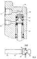
- the hydraulic proportioning valve for use on an automotive vehicle comprises a body 10 in which is formed a longitudinal stepped bore 12.
- the bore 12 communicates at a closed end with a fluid outlet 14 which is intended, in use, to be connected to the rear brakes of the vehicle (not shown) and, at a point along the length of the bore 12, with a fluid inlet 16 intended, in use, to be connected to a source of hydraulic pressure, for example the vehicle master cylinder (not shown).
- a tubular sleeve 18 is fixedly mounted in the bore 12 by means of an annular circlip 20.
- a piston 22 is located in the bore 12 and comprises a longitudinally extending stem 24 which is slideably received in the sleeve 18.
- the bore 12 is sealed by two annular seals 26 and 28.
- the piston 22 comprises a generally cylindrical head 30 which is received, with play, in an end part 32 of reduced diameter of the bore 12.
- the piston 22 comprises a central portion 34 of increased diameter and which carries an annular collar 36 which is cut at one point by an opening 38.
- One end of a helical spring 40 bears against the collar 36 and the other end bears against a metal ring 41 mounted around the seal 26.
- the spring 40 thus tends to urge the piston 22 towards its rest position illustrated in Figure 1 in which the head 30 engages the end wall of the bore 12.
- An annular composite seal 42 is mounted in the bore 12 adjacent a shoulder 44 and the end of the part of the bore of increased diameter.
- the seal 42 comprises an outer ring 46 having a generally C-shaped cross-section and which is made of an elastomeric material such as rubber.
- the seal 42 also comprises an inner ring 48 which is made of a material having a low coefficient of friction such as polytetrafluoroethylene.
- This inner ring 48 has an external flange 50 which is received in the jaws of the C-shaped outer ring 46.
- the composite seal 42 is free to slide in the bore 12.
- the stem 24 may be linked by a spring arrangement to the suspension of the vehicle in a way known per se in order to make the proportioning valve responsive to the load of the vehicle.
- Figure 1 shows the valve in its rest position with the head 30 of piston 22 urged into abutment with the end of the bore 12 by the spring 40.
- braking fluid under pressure passes in the direction of the arrows from the inlet 16 by way of the bore 12, opening 38 and an annular passage 52 between the head 30 and the bore 12 to the outlet 14 and thence to the brakes of the rear wheels of the vehicle.
- the rear braking pressure P F corresponds to the section 0-1 of the graph shown in Figure 2.
Landscapes
- Engineering & Computer Science (AREA)
- Transportation (AREA)
- Mechanical Engineering (AREA)
- Hydraulic Control Valves For Brake Systems (AREA)
- Safety Valves (AREA)
Claims (3)
- Hydraulisches Dosierventil mit einem Gehäuse (10), in dem eine Bohrung ausgebildet ist, die einen Endteil (32) mit reduziertem Durchmesser, der mit einem Auslaß (14) in Verbindung steht, und einen größeren Teil (12) aufweist, der mit einem Einlaß (16) in Verbindung steht, wobei der Endteil (32) und der größere Teil (12) durch eine Schulter (44) voneinander getrennt sind, einem Kolben (22), der gleitend in der Bohrung montiert ist und einen allgemein zylindrischen Kopf (30), der im Endteil (32) mit reduziertem Durchmesser der Bohrung angeordnet ist, und einen ringförmigen Kragen (36) umfaßt, wobei eine Ringdichtung (42) gleitend im größeren Teil (12) der Bohrung montiert ist und der Kolben (22) durch eine Feder (40) in eine Ruhelage gepreßt wird, in der der ringförmige Kragen (36) die Ringdichtung (42) gegen die Schulter (44) drückt, dadurch gekennzeichnet, daß der ringförmige Kragen (36) an einem Punkt durch eine Öffnung (38) durchtrennt ist und daß der zylindrische Kopf (30) des Kolbens (22) durch die Ringdichtung (42) gleiten kann.
- Dosierventil nach Anspruch 1, dadurch gekennzeichnet, daß die Ringdichtung (42) eine Verbunddichtung ist und einen Außenring (46) aus einem ersten Material umfaßt, in dem ein Innenring (48) aus einem zweiten Material mit einem niedrigeren Reibungskoeffizienten als dem des ersten Materiales angeordnet ist.
- Dosierventil nach Anspruch 2, dadurch gekennzeichnet, daß der Außenring (46) einen allgemein C-förmigen Querschnitt besitzt und daß der Innenring (48) einen Außenflansch (50) aufweist, der innerhalb der Schenkel des C-förmigen Außenringes (46) angeordnet ist.
Applications Claiming Priority (2)
| Application Number | Priority Date | Filing Date | Title |
|---|---|---|---|
| IT20652/88A IT1217661B (it) | 1988-05-20 | 1988-05-20 | Valvola proporzionatrice idraulica,particolarmente per freni di autoveicoli |
| IT2065288 | 1988-05-20 |
Publications (2)
| Publication Number | Publication Date |
|---|---|
| EP0343028A1 EP0343028A1 (de) | 1989-11-23 |
| EP0343028B1 true EP0343028B1 (de) | 1992-11-04 |
Family
ID=11170077
Family Applications (1)
| Application Number | Title | Priority Date | Filing Date |
|---|---|---|---|
| EP89401115A Expired EP0343028B1 (de) | 1988-05-20 | 1989-04-21 | Hydraulisches Dosierventil |
Country Status (6)
| Country | Link |
|---|---|
| US (1) | US5052760A (de) |
| EP (1) | EP0343028B1 (de) |
| JP (1) | JP2772542B2 (de) |
| DE (1) | DE68903358T2 (de) |
| ES (1) | ES2035599T3 (de) |
| IT (1) | IT1217661B (de) |
Families Citing this family (3)
| Publication number | Priority date | Publication date | Assignee | Title |
|---|---|---|---|---|
| GB9001565D0 (en) * | 1990-01-23 | 1990-03-21 | Gen Motors France | Disc brake |
| US5698284A (en) | 1994-09-21 | 1997-12-16 | Dai Nippon Printing Co., Ltd. | Optical recording medium |
| US5879010A (en) * | 1997-07-22 | 1999-03-09 | Green Tweed Of Delaware, Inc. | Seal assembly with mechanically joined anti-extrusion rings |
Family Cites Families (15)
| Publication number | Priority date | Publication date | Assignee | Title |
|---|---|---|---|---|
| US31171A (en) * | 1861-01-22 | Improvement in sewinq-machine s | ||
| FR1439476A (fr) * | 1965-06-24 | 1966-05-20 | Teves Kg Alfred | Soupape de réduction |
| US3278241A (en) * | 1965-08-13 | 1966-10-11 | Kelsey Hayes Co | Pressure metering valve |
| CH447042A (fr) * | 1965-09-24 | 1968-03-15 | Tissot Horlogerie | Dispositif de fixation de l'extrémité extérieure d'un spiral réglant de pièce d'horlogerie |
| FR2155887B1 (de) * | 1971-10-13 | 1974-05-31 | Dba | |
| US3848880A (en) * | 1972-06-09 | 1974-11-19 | Tanner Eng Co | Fluid seal |
| GB1531001A (en) * | 1975-03-17 | 1978-11-01 | Girling Ltd | Pressure control valves |
| GB1557006A (en) * | 1975-07-14 | 1979-12-05 | Girling Ltd | Vehicle load sensing arrangements |
| IT1041425B (it) * | 1975-07-29 | 1980-01-10 | Fiat Spa | Dispositivo di regolazione per impianti pneumatici di frenatura per autoveicoli |
| IT1040409B (it) * | 1975-08-05 | 1979-12-20 | Benditalia Spa | Valvola correttrice di frenatura |
| BR7701957A (pt) * | 1976-03-30 | 1978-01-24 | Girling Ltd | Valvula redutora de pressao para sistema de frenagem de veiculo |
| DE2613957C2 (de) * | 1976-04-01 | 1983-08-11 | Alfred Teves Gmbh, 6000 Frankfurt | Bremskraftverteiler für hydraulische Bremssysteme |
| DE2638190C2 (de) * | 1976-08-25 | 1986-04-10 | Alfred Teves Gmbh, 6000 Frankfurt | Drucksteuereinheit für hydraulische Fahrzeugbremsanlagen |
| USRE31171E (en) | 1978-05-26 | 1983-03-08 | Textron, Inc. | Hydraulic piston rod seal |
| DE3615154A1 (de) * | 1986-05-05 | 1987-11-12 | Teves Gmbh Alfred | Bremsdruckregelventilanordnung |
-
1988
- 1988-05-20 IT IT20652/88A patent/IT1217661B/it active
-
1989
- 1989-04-21 ES ES198989401115T patent/ES2035599T3/es not_active Expired - Lifetime
- 1989-04-21 EP EP89401115A patent/EP0343028B1/de not_active Expired
- 1989-04-21 DE DE8989401115T patent/DE68903358T2/de not_active Expired - Fee Related
- 1989-05-18 US US07/353,927 patent/US5052760A/en not_active Expired - Lifetime
- 1989-05-19 JP JP1124602A patent/JP2772542B2/ja not_active Expired - Lifetime
Also Published As
| Publication number | Publication date |
|---|---|
| ES2035599T3 (es) | 1993-04-16 |
| JPH0218143A (ja) | 1990-01-22 |
| EP0343028A1 (de) | 1989-11-23 |
| JP2772542B2 (ja) | 1998-07-02 |
| IT8820652A0 (it) | 1988-05-20 |
| IT1217661B (it) | 1990-03-30 |
| DE68903358D1 (de) | 1992-12-10 |
| US5052760A (en) | 1991-10-01 |
| DE68903358T2 (de) | 1993-04-08 |
Similar Documents
| Publication | Publication Date | Title |
|---|---|---|
| US4890890A (en) | Vehicle brake system having an anti-skid apparatus | |
| US3493270A (en) | Impulse check valve | |
| GB1580390A (en) | Device for use in a hydryulic braking system incorporating anti-skid control apparatus | |
| US6085522A (en) | Boosted braking device with variable boost ratio and reduced hysteresis | |
| GB1588038A (en) | Pressure-control unit for vehicular hydraulic brake system | |
| EP0343028B1 (de) | Hydraulisches Dosierventil | |
| US4184716A (en) | Control valve assembly for hydraulic brakes | |
| US4111495A (en) | Load sensing proportioner with proportioner delay | |
| US3844623A (en) | Anti-skid control means for air pressure braking systems | |
| KR100242255B1 (ko) | 다중경사 보상기 | |
| US3210941A (en) | Pressure proportioning master cylinder | |
| US5273141A (en) | Bleed valve for a hydraulic circuit and process for bleeding a hydraulic circuit equipped with such a valve | |
| US3706477A (en) | Proportioning device | |
| US3973578A (en) | Tandem control valve | |
| US3414334A (en) | Delaying action equalizer valve | |
| US4901626A (en) | Hydraulic power booster | |
| US4730878A (en) | Skid-controlled hydraulic brake system | |
| US4726626A (en) | Servo brake automodulator for trailers with pneumatic brake systems | |
| US3994533A (en) | Inertia-type hydraulic brake pressure control valve | |
| US4008925A (en) | Valve devices for use in liquid pressure braking systems of vehicles | |
| EP0089478B1 (de) | Bremsdruckregelventil für Zweikreisanlage | |
| US4103976A (en) | Two-pressure brake control valve for single stage releasing indirectly acting airbrakes | |
| US4325582A (en) | Hydraulic pressure control valve assembly for automotive hydraulic brake system | |
| US6213566B1 (en) | Brake proportioning in-line ball valve | |
| US4365845A (en) | Hydraulic brake pressure control valve |
Legal Events
| Date | Code | Title | Description |
|---|---|---|---|
| PUAI | Public reference made under article 153(3) epc to a published international application that has entered the european phase |
Free format text: ORIGINAL CODE: 0009012 |
|
| AK | Designated contracting states |
Kind code of ref document: A1 Designated state(s): DE ES FR GB IT |
|
| 17P | Request for examination filed |
Effective date: 19891020 |
|
| 17Q | First examination report despatched |
Effective date: 19910321 |
|
| GRAA | (expected) grant |
Free format text: ORIGINAL CODE: 0009210 |
|
| AK | Designated contracting states |
Kind code of ref document: B1 Designated state(s): DE ES FR GB IT |
|
| REF | Corresponds to: |
Ref document number: 68903358 Country of ref document: DE Date of ref document: 19921210 |
|
| ITF | It: translation for a ep patent filed | ||
| ET | Fr: translation filed | ||
| REG | Reference to a national code |
Ref country code: ES Ref legal event code: FG2A Ref document number: 2035599 Country of ref document: ES Kind code of ref document: T3 |
|
| PLBE | No opposition filed within time limit |
Free format text: ORIGINAL CODE: 0009261 |
|
| STAA | Information on the status of an ep patent application or granted ep patent |
Free format text: STATUS: NO OPPOSITION FILED WITHIN TIME LIMIT |
|
| 26N | No opposition filed | ||
| PGFP | Annual fee paid to national office [announced via postgrant information from national office to epo] |
Ref country code: GB Payment date: 19940412 Year of fee payment: 6 |
|
| PGFP | Annual fee paid to national office [announced via postgrant information from national office to epo] |
Ref country code: DE Payment date: 19940426 Year of fee payment: 6 |
|
| PG25 | Lapsed in a contracting state [announced via postgrant information from national office to epo] |
Ref country code: GB Effective date: 19950421 |
|
| GBPC | Gb: european patent ceased through non-payment of renewal fee |
Effective date: 19950421 |
|
| PG25 | Lapsed in a contracting state [announced via postgrant information from national office to epo] |
Ref country code: DE Effective date: 19960103 |
|
| PGFP | Annual fee paid to national office [announced via postgrant information from national office to epo] |
Ref country code: ES Payment date: 20080424 Year of fee payment: 20 |
|
| PGFP | Annual fee paid to national office [announced via postgrant information from national office to epo] |
Ref country code: IT Payment date: 20080428 Year of fee payment: 20 |
|
| PGFP | Annual fee paid to national office [announced via postgrant information from national office to epo] |
Ref country code: FR Payment date: 20080418 Year of fee payment: 20 |
|
| REG | Reference to a national code |
Ref country code: ES Ref legal event code: FD2A Effective date: 20090422 |
|
| PG25 | Lapsed in a contracting state [announced via postgrant information from national office to epo] |
Ref country code: ES Free format text: LAPSE BECAUSE OF EXPIRATION OF PROTECTION Effective date: 20090422 |