EP0343028B1 - Hydraulic proportioning valve - Google Patents
Hydraulic proportioning valve Download PDFInfo
- Publication number
- EP0343028B1 EP0343028B1 EP89401115A EP89401115A EP0343028B1 EP 0343028 B1 EP0343028 B1 EP 0343028B1 EP 89401115 A EP89401115 A EP 89401115A EP 89401115 A EP89401115 A EP 89401115A EP 0343028 B1 EP0343028 B1 EP 0343028B1
- Authority
- EP
- European Patent Office
- Prior art keywords
- bore
- piston
- proportioning valve
- seal
- annular
- Prior art date
- Legal status (The legal status is an assumption and is not a legal conclusion. Google has not performed a legal analysis and makes no representation as to the accuracy of the status listed.)
- Expired
Links
Images


Classifications
-
- B—PERFORMING OPERATIONS; TRANSPORTING
- B60—VEHICLES IN GENERAL
- B60T—VEHICLE BRAKE CONTROL SYSTEMS OR PARTS THEREOF; BRAKE CONTROL SYSTEMS OR PARTS THEREOF, IN GENERAL; ARRANGEMENT OF BRAKING ELEMENTS ON VEHICLES IN GENERAL; PORTABLE DEVICES FOR PREVENTING UNWANTED MOVEMENT OF VEHICLES; VEHICLE MODIFICATIONS TO FACILITATE COOLING OF BRAKES
- B60T8/00—Arrangements for adjusting wheel-braking force to meet varying vehicular or ground-surface conditions, e.g. limiting or varying distribution of braking force
- B60T8/18—Arrangements for adjusting wheel-braking force to meet varying vehicular or ground-surface conditions, e.g. limiting or varying distribution of braking force responsive to vehicle weight or load, e.g. load distribution
- B60T8/1812—Arrangements for adjusting wheel-braking force to meet varying vehicular or ground-surface conditions, e.g. limiting or varying distribution of braking force responsive to vehicle weight or load, e.g. load distribution characterised by the means for pressure reduction
- B60T8/1831—Arrangements for adjusting wheel-braking force to meet varying vehicular or ground-surface conditions, e.g. limiting or varying distribution of braking force responsive to vehicle weight or load, e.g. load distribution characterised by the means for pressure reduction pressure reducing or limiting valves
-
- B—PERFORMING OPERATIONS; TRANSPORTING
- B60—VEHICLES IN GENERAL
- B60T—VEHICLE BRAKE CONTROL SYSTEMS OR PARTS THEREOF; BRAKE CONTROL SYSTEMS OR PARTS THEREOF, IN GENERAL; ARRANGEMENT OF BRAKING ELEMENTS ON VEHICLES IN GENERAL; PORTABLE DEVICES FOR PREVENTING UNWANTED MOVEMENT OF VEHICLES; VEHICLE MODIFICATIONS TO FACILITATE COOLING OF BRAKES
- B60T11/00—Transmitting braking action from initiating means to ultimate brake actuator without power assistance or drive or where such assistance or drive is irrelevant
- B60T11/10—Transmitting braking action from initiating means to ultimate brake actuator without power assistance or drive or where such assistance or drive is irrelevant transmitting by fluid means, e.g. hydraulic
- B60T11/28—Valves specially adapted therefor
- B60T11/34—Pressure reducing or limiting valves
-
- B—PERFORMING OPERATIONS; TRANSPORTING
- B60—VEHICLES IN GENERAL
- B60T—VEHICLE BRAKE CONTROL SYSTEMS OR PARTS THEREOF; BRAKE CONTROL SYSTEMS OR PARTS THEREOF, IN GENERAL; ARRANGEMENT OF BRAKING ELEMENTS ON VEHICLES IN GENERAL; PORTABLE DEVICES FOR PREVENTING UNWANTED MOVEMENT OF VEHICLES; VEHICLE MODIFICATIONS TO FACILITATE COOLING OF BRAKES
- B60T8/00—Arrangements for adjusting wheel-braking force to meet varying vehicular or ground-surface conditions, e.g. limiting or varying distribution of braking force
- B60T8/26—Arrangements for adjusting wheel-braking force to meet varying vehicular or ground-surface conditions, e.g. limiting or varying distribution of braking force characterised by producing differential braking between front and rear wheels
- B60T8/262—Arrangements for adjusting wheel-braking force to meet varying vehicular or ground-surface conditions, e.g. limiting or varying distribution of braking force characterised by producing differential braking between front and rear wheels using valves with stepped characteristics
- B60T8/265—Arrangements for adjusting wheel-braking force to meet varying vehicular or ground-surface conditions, e.g. limiting or varying distribution of braking force characterised by producing differential braking between front and rear wheels using valves with stepped characteristics for hydraulic brake systems
-
- B—PERFORMING OPERATIONS; TRANSPORTING
- B60—VEHICLES IN GENERAL
- B60T—VEHICLE BRAKE CONTROL SYSTEMS OR PARTS THEREOF; BRAKE CONTROL SYSTEMS OR PARTS THEREOF, IN GENERAL; ARRANGEMENT OF BRAKING ELEMENTS ON VEHICLES IN GENERAL; PORTABLE DEVICES FOR PREVENTING UNWANTED MOVEMENT OF VEHICLES; VEHICLE MODIFICATIONS TO FACILITATE COOLING OF BRAKES
- B60T8/00—Arrangements for adjusting wheel-braking force to meet varying vehicular or ground-surface conditions, e.g. limiting or varying distribution of braking force
- B60T8/26—Arrangements for adjusting wheel-braking force to meet varying vehicular or ground-surface conditions, e.g. limiting or varying distribution of braking force characterised by producing differential braking between front and rear wheels
- B60T8/30—Arrangements for adjusting wheel-braking force to meet varying vehicular or ground-surface conditions, e.g. limiting or varying distribution of braking force characterised by producing differential braking between front and rear wheels responsive to load
- B60T8/306—Arrangements for adjusting wheel-braking force to meet varying vehicular or ground-surface conditions, e.g. limiting or varying distribution of braking force characterised by producing differential braking between front and rear wheels responsive to load using hydraulic valves
Definitions
- the present invention relates to a hydraulic proportioning valve and, more particularly to such valves intended for use in the brake circuits of automotive vehicles.
- the proportioning valve described in GB-A-1531001 has a piston assembly displaceable in a bore in the valve under the influence of hydraulic pressure, between an open position and a closed position where the piston engages an inwardly projecting annular lip on a ring seal fixedly mounted in the bore. Upon decrease of the applied pressure the annular lip tilts to allow fluid to flow back from the brakes towards the master cylinder. Due to its structure, and especially due to the use of a tilting lip, the hysteresis of this device is too great to allow it to be used in an anti-skid circuit.
- Document FR-A-2 320 216 discloses a hydraulic proportioning valve comprising a body in which is formed a bore having an end part of reduced diameter which communicates with an outlet, and a larger part which communicates with an inlet, a piston is separated by a shoulder slideably mounted in the bore, and comprises a generally cylindrical head received in the end part of reduced diameter of the bore, and an annular collar.
- An annular seal is slideably mounted in the larger part of the bore, the piston is urged by a spring in a rest position in which the annular collar urges the annular seal against the shoulder.
- the head of the piston of this document comprises another annular collar engaging the annular seal for closing the communication between the two parts of the bore. Due to this design, upon release of braking, the annular seal opposes a force against the increase of volume of the part of the bore of reduced diameter, thus generating an hysteresis.
- the annular collar is cut in one point by an opening and the cylindrical head of the piston is allowed to slide through the annular seal.
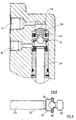
- the hydraulic proportioning valve for use on an automotive vehicle comprises a body 10 in which is formed a longitudinal stepped bore 12.
- the bore 12 communicates at a closed end with a fluid outlet 14 which is intended, in use, to be connected to the rear brakes of the vehicle (not shown) and, at a point along the length of the bore 12, with a fluid inlet 16 intended, in use, to be connected to a source of hydraulic pressure, for example the vehicle master cylinder (not shown).
- a tubular sleeve 18 is fixedly mounted in the bore 12 by means of an annular circlip 20.
- a piston 22 is located in the bore 12 and comprises a longitudinally extending stem 24 which is slideably received in the sleeve 18.
- the bore 12 is sealed by two annular seals 26 and 28.
- the piston 22 comprises a generally cylindrical head 30 which is received, with play, in an end part 32 of reduced diameter of the bore 12.
- the piston 22 comprises a central portion 34 of increased diameter and which carries an annular collar 36 which is cut at one point by an opening 38.
- One end of a helical spring 40 bears against the collar 36 and the other end bears against a metal ring 41 mounted around the seal 26.
- the spring 40 thus tends to urge the piston 22 towards its rest position illustrated in Figure 1 in which the head 30 engages the end wall of the bore 12.
- An annular composite seal 42 is mounted in the bore 12 adjacent a shoulder 44 and the end of the part of the bore of increased diameter.
- the seal 42 comprises an outer ring 46 having a generally C-shaped cross-section and which is made of an elastomeric material such as rubber.
- the seal 42 also comprises an inner ring 48 which is made of a material having a low coefficient of friction such as polytetrafluoroethylene.
- This inner ring 48 has an external flange 50 which is received in the jaws of the C-shaped outer ring 46.
- the composite seal 42 is free to slide in the bore 12.
- the stem 24 may be linked by a spring arrangement to the suspension of the vehicle in a way known per se in order to make the proportioning valve responsive to the load of the vehicle.
- Figure 1 shows the valve in its rest position with the head 30 of piston 22 urged into abutment with the end of the bore 12 by the spring 40.
- braking fluid under pressure passes in the direction of the arrows from the inlet 16 by way of the bore 12, opening 38 and an annular passage 52 between the head 30 and the bore 12 to the outlet 14 and thence to the brakes of the rear wheels of the vehicle.
- the rear braking pressure P F corresponds to the section 0-1 of the graph shown in Figure 2.
Description
- The present invention relates to a hydraulic proportioning valve and, more particularly to such valves intended for use in the brake circuits of automotive vehicles.
- During the braking of a vehicle most of the load is taken by the front wheels. If equal hydraulic pressures are applied to the front and rear wheels of the vehicle the rear wheels will tend to lock before the front wheels due to their lesser load. In order to avoid this undesirable occurrence a proportioning valve is generally included in the hydraulic line to the rear brakes so as to limit the pressure increase when the rear braking pressure exceeds a certain value. A example of such a correcting valve is given in the document GB-A-1,531,001.
- With modern vehicles it is increasingly common to include an anti-skid system in the braking circuit. In operation such a circuit requires that the hydraulic pressure applied to the vehicle brakes vary very rapidly. It is important therefore that the proportioning valve does not impede this rapid variation in braking pressure.
- The proportioning valve described in GB-A-1531001 has a piston assembly displaceable in a bore in the valve under the influence of hydraulic pressure, between an open position and a closed position where the piston engages an inwardly projecting annular lip on a ring seal fixedly mounted in the bore. Upon decrease of the applied pressure the annular lip tilts to allow fluid to flow back from the brakes towards the master cylinder. Due to its structure, and especially due to the use of a tilting lip, the hysteresis of this device is too great to allow it to be used in an anti-skid circuit.
- Document FR-A-2 320 216 discloses a hydraulic proportioning valve comprising a body in which is formed a bore having an end part of reduced diameter which communicates with an outlet, and a larger part which communicates with an inlet, a piston is separated by a shoulder slideably mounted in the bore, and comprises a generally cylindrical head received in the end part of reduced diameter of the bore, and an annular collar. An annular seal is slideably mounted in the larger part of the bore, the piston is urged by a spring in a rest position in which the annular collar urges the annular seal against the shoulder.
- The preamble of
Claim 1 is based on this document. - However, the head of the piston of this document comprises another annular collar engaging the annular seal for closing the communication between the two parts of the bore. Due to this design, upon release of braking, the annular seal opposes a force against the increase of volume of the part of the bore of reduced diameter, thus generating an hysteresis.
- It is therefore an object of the invention to provide a hydraulic proportioning valve of this type, which is reliable and whose response characteristics and especially whose hysteresis characteristics make it suitable for use in a vehicle braking circuit which includes an antiskid system.
- According to the invention, the annular collar is cut in one point by an opening and the cylindrical head of the piston is allowed to slide through the annular seal.
- One embodiment of the invention will now be described by way of example with reference to the accompanying drawings in which :
- Figure 1 is a partial longitudinal section through a hydraulic proportioning valve in accordance with the present invention ;
- Figure 2 is a graph showing the pressure response characteristics of the valve of Figure 1 ;
- Figure 3,4 and 5 are each views similar to that of Figure 1 showing the proportioning valve in various stages of operation ; and
- Figure 6 is a detailed view of a component of Figure 1.
- As shown in Figure 1 the hydraulic proportioning valve for use on an automotive vehicle comprises a
body 10 in which is formed alongitudinal stepped bore 12. Thebore 12 communicates at a closed end with afluid outlet 14 which is intended, in use, to be connected to the rear brakes of the vehicle (not shown) and, at a point along the length of thebore 12, with afluid inlet 16 intended, in use, to be connected to a source of hydraulic pressure, for example the vehicle master cylinder (not shown). Atubular sleeve 18 is fixedly mounted in thebore 12 by means of anannular circlip 20. Apiston 22 is located in thebore 12 and comprises a longitudinally extendingstem 24 which is slideably received in thesleeve 18. Thebore 12 is sealed by twoannular seals - The
piston 22 comprises a generallycylindrical head 30 which is received, with play, in anend part 32 of reduced diameter of thebore 12. As can more clearly be seen in Figure 6 thepiston 22 comprises acentral portion 34 of increased diameter and which carries anannular collar 36 which is cut at one point by anopening 38. One end of ahelical spring 40 bears against thecollar 36 and the other end bears against ametal ring 41 mounted around theseal 26. Thespring 40 thus tends to urge thepiston 22 towards its rest position illustrated in Figure 1 in which thehead 30 engages the end wall of thebore 12. An annularcomposite seal 42 is mounted in thebore 12 adjacent ashoulder 44 and the end of the part of the bore of increased diameter. Theseal 42 comprises anouter ring 46 having a generally C-shaped cross-section and which is made of an elastomeric material such as rubber. Theseal 42 also comprises aninner ring 48 which is made of a material having a low coefficient of friction such as polytetrafluoroethylene. Thisinner ring 48 has anexternal flange 50 which is received in the jaws of the C-shapedouter ring 46. As will be seen below, thecomposite seal 42 is free to slide in thebore 12. In use thestem 24 may be linked by a spring arrangement to the suspension of the vehicle in a way known per se in order to make the proportioning valve responsive to the load of the vehicle. - The proportioning valve which has been described above operates as follows.
- Figure 1 shows the valve in its rest position with the
head 30 ofpiston 22 urged into abutment with the end of thebore 12 by thespring 40. During braking fluid under pressure passes in the direction of the arrows from theinlet 16 by way of thebore 12, opening 38 and anannular passage 52 between thehead 30 and thebore 12 to theoutlet 14 and thence to the brakes of the rear wheels of the vehicle. During this initial phase the rear braking pressure PF corresponds to the section 0-1 of the graph shown in Figure 2. - When the hydraulic pressure acting on the cross section of the
stem 24 exceeds the force exerted on thepiston 22 by thespring 40 thepiston 22 moves away from the end of thebore 12 and the outer surface of thehead 30 engages the inner surface of theseal 42. This position is shown in Figure 3. In this position the piston is in equilibrium and further increase in the inlet pressure will result in modulation of the piston between its closed position and a partially open position in a way which is known per se. Pressure to the rear brakes will thus increase at a lower rate than pressure to the front brakes. This phase corresponds to the section 1-2 on the graph of Figure 2. - Upon release of braking, whether in conventional circumstances, or when the brake circuit is in the anti-skid mode, the hydraulic pressure at the
inlet 16 decreases. This produces a pressure differential across thepiston head 30 which causes thepiston 22 to move away from the end of thebore 12 with thepiston head 30 sliding through theseal 42. Thepiston 22 slides down towards a lower position whose maximum limit is defined by thecentral portion 34 coming into abutment against themetal ring 41. This position corresponds to that shown in Figure 4. During the displacement of thepiston 22 the volume of the part of thebore 12 of reduceddiameter 54 increases. This increase in volume creates a corresponding decrease in pressure applied to the brakes. This phase of braking is shown by the section 2-3 of the graph in Figure 2. - When the
piston 22 has reached its abutment position shown in Figure 4 a further decrease in braking pressure at the rear wheels can be brought about by a further increase in the volume of thelower part 54 of thebore 12 allowed by an inversion of the pressure difference across thepiston head 30. This increase is assured by theseal 42 which slides in thebore 12 from its position in which it engagesshoulder 44 to the position shown in Figure 5, and thus allows the pressures on each side of the piston to equalize. This further decrease in pressure corresponds to the section 3-1 on the graph of Figure 2. - Thus, from Figure 2 it will be seen that the hysterisis of the present proportioning valve is very low making it particularly suitable for use in a brake circuit which includes an anti-skid system.
- When the brakes of the vehicle are completely released the
piston 22 returns to its rest position shown in Figure 1, theannular collar 36 pushes the seal back into its position in which it engages theshoulder 44 of thebore 12. - It is envisaged that the present invention also be applied to double proportioning valves.
Claims (3)
- A hydraulic proportioning valve comprising a body (10) in which is formed a bore having an end part (32) of reduced diameter which communicates with an outlet (14), and a larger part (12) which communicates with an inlet (16), said end part (32) and said larger part (12) being separated by a shoulder (44), a piston (22) being slideably mounted in the bore, said piston (22) comprising a generally cylindrical head (30) received in said end part (32) of reduced diameter of the bore, and an annular collar (36), an annular seal (42) being slideably mounted in the larger part (12) of the bore, said piston (22) being urged by a spring (40) in a rest position in which said annular collar (36) urges said annualar seal (42) against said shoulder (44), characterized in that said annular collar (36) is cut at one point by an opening (38), and in that said cylindrical head (30) of said piston (22) is allowed to slide through said annular seal (42).
- Proportioning valve as claimed in Claim 1, characterized in that said annular seal (42) is composite and comprises an outer ring (46) of a first material, in which is received an inner ring (48) of a second material having a lower coefficient of friction than that of the first material.
- Proportioning valve as claimed in Claim 2, characterized in that the outer ring (46) has a generally C-Shaped cross-section, the inner ring (48) comprising an external flange (50) which is received within the jaws of the C-Shaped outer ring (46).
Applications Claiming Priority (2)
| Application Number | Priority Date | Filing Date | Title |
|---|---|---|---|
| IT2065288 | 1988-05-20 | ||
| IT20652/88A IT1217661B (en) | 1988-05-20 | 1988-05-20 | HYDRAULIC PROPORTIONING VALVE, PARTICULARLY FOR VEHICLE BRAKES |
Publications (2)
| Publication Number | Publication Date |
|---|---|
| EP0343028A1 EP0343028A1 (en) | 1989-11-23 |
| EP0343028B1 true EP0343028B1 (en) | 1992-11-04 |
Family
ID=11170077
Family Applications (1)
| Application Number | Title | Priority Date | Filing Date |
|---|---|---|---|
| EP89401115A Expired EP0343028B1 (en) | 1988-05-20 | 1989-04-21 | Hydraulic proportioning valve |
Country Status (6)
| Country | Link |
|---|---|
| US (1) | US5052760A (en) |
| EP (1) | EP0343028B1 (en) |
| JP (1) | JP2772542B2 (en) |
| DE (1) | DE68903358T2 (en) |
| ES (1) | ES2035599T3 (en) |
| IT (1) | IT1217661B (en) |
Families Citing this family (3)
| Publication number | Priority date | Publication date | Assignee | Title |
|---|---|---|---|---|
| GB9001565D0 (en) * | 1990-01-23 | 1990-03-21 | Gen Motors France | Disc brake |
| US5698284A (en) | 1994-09-21 | 1997-12-16 | Dai Nippon Printing Co., Ltd. | Optical recording medium |
| US5879010A (en) * | 1997-07-22 | 1999-03-09 | Green Tweed Of Delaware, Inc. | Seal assembly with mechanically joined anti-extrusion rings |
Family Cites Families (14)
| Publication number | Priority date | Publication date | Assignee | Title |
|---|---|---|---|---|
| US31171A (en) * | 1861-01-22 | Improvement in sewinq-machine s | ||
| FR1439476A (en) * | 1965-06-24 | 1966-05-20 | Teves Kg Alfred | Reduction valve |
| US3278241A (en) * | 1965-08-13 | 1966-10-11 | Kelsey Hayes Co | Pressure metering valve |
| CH447042A (en) * | 1965-09-24 | 1968-03-15 | Tissot Horlogerie | Fixing device for the outer end of a regulating balance spring for a timepiece |
| FR2155887B1 (en) * | 1971-10-13 | 1974-05-31 | Dba | |
| US3848880A (en) * | 1972-06-09 | 1974-11-19 | Tanner Eng Co | Fluid seal |
| GB1531001A (en) * | 1975-03-17 | 1978-11-01 | Girling Ltd | Pressure control valves |
| GB1557006A (en) * | 1975-07-14 | 1979-12-05 | Girling Ltd | Vehicle load sensing arrangements |
| IT1041425B (en) * | 1975-07-29 | 1980-01-10 | Fiat Spa | ADJUSTMENT DEVICE FOR PNEUMATIC BRAKING SYSTEMS FOR VEHICLES |
| IT1040409B (en) * | 1975-08-05 | 1979-12-20 | Benditalia Spa | BRAKING CORRECTIVE VALVE |
| BR7701957A (en) * | 1976-03-30 | 1978-01-24 | Girling Ltd | PRESSURE REDUCING VALVE FOR VEHICLE BRAKING SYSTEM |
| DE2613957C2 (en) * | 1976-04-01 | 1983-08-11 | Alfred Teves Gmbh, 6000 Frankfurt | Brake force distributor for hydraulic brake systems |
| DE2638190C2 (en) * | 1976-08-25 | 1986-04-10 | Alfred Teves Gmbh, 6000 Frankfurt | Pressure control unit for hydraulic vehicle brake systems |
| DE3615154A1 (en) * | 1986-05-05 | 1987-11-12 | Teves Gmbh Alfred | Brake pressure control valve arrangement |
-
1988
- 1988-05-20 IT IT20652/88A patent/IT1217661B/en active
-
1989
- 1989-04-21 ES ES198989401115T patent/ES2035599T3/en not_active Expired - Lifetime
- 1989-04-21 EP EP89401115A patent/EP0343028B1/en not_active Expired
- 1989-04-21 DE DE8989401115T patent/DE68903358T2/en not_active Expired - Fee Related
- 1989-05-18 US US07/353,927 patent/US5052760A/en not_active Expired - Lifetime
- 1989-05-19 JP JP1124602A patent/JP2772542B2/en not_active Expired - Lifetime
Also Published As
| Publication number | Publication date |
|---|---|
| DE68903358D1 (en) | 1992-12-10 |
| DE68903358T2 (en) | 1993-04-08 |
| JPH0218143A (en) | 1990-01-22 |
| US5052760A (en) | 1991-10-01 |
| EP0343028A1 (en) | 1989-11-23 |
| IT1217661B (en) | 1990-03-30 |
| IT8820652A0 (en) | 1988-05-20 |
| JP2772542B2 (en) | 1998-07-02 |
| ES2035599T3 (en) | 1993-04-16 |
Similar Documents
| Publication | Publication Date | Title |
|---|---|---|
| US3493270A (en) | Impulse check valve | |
| GB1580390A (en) | Device for use in a hydryulic braking system incorporating anti-skid control apparatus | |
| US6085522A (en) | Boosted braking device with variable boost ratio and reduced hysteresis | |
| GB1588038A (en) | Pressure-control unit for vehicular hydraulic brake system | |
| EP0343028B1 (en) | Hydraulic proportioning valve | |
| US4184716A (en) | Control valve assembly for hydraulic brakes | |
| US4111495A (en) | Load sensing proportioner with proportioner delay | |
| US3844623A (en) | Anti-skid control means for air pressure braking systems | |
| JP2000508414A (en) | Annular sealing member | |
| US3210941A (en) | Pressure proportioning master cylinder | |
| US5273141A (en) | Bleed valve for a hydraulic circuit and process for bleeding a hydraulic circuit equipped with such a valve | |
| US3706477A (en) | Proportioning device | |
| US3973578A (en) | Tandem control valve | |
| US3414334A (en) | Delaying action equalizer valve | |
| US4901626A (en) | Hydraulic power booster | |
| US4730878A (en) | Skid-controlled hydraulic brake system | |
| US4726626A (en) | Servo brake automodulator for trailers with pneumatic brake systems | |
| US3994533A (en) | Inertia-type hydraulic brake pressure control valve | |
| US4008925A (en) | Valve devices for use in liquid pressure braking systems of vehicles | |
| EP0089478B1 (en) | A brake pressure control valve for a double piping braking system | |
| US4103976A (en) | Two-pressure brake control valve for single stage releasing indirectly acting airbrakes | |
| US4325582A (en) | Hydraulic pressure control valve assembly for automotive hydraulic brake system | |
| US4265490A (en) | Pressure control valve for a vehicle hydraulic brake system | |
| US6213566B1 (en) | Brake proportioning in-line ball valve | |
| US4365845A (en) | Hydraulic brake pressure control valve |
Legal Events
| Date | Code | Title | Description |
|---|---|---|---|
| PUAI | Public reference made under article 153(3) epc to a published international application that has entered the european phase |
Free format text: ORIGINAL CODE: 0009012 |
|
| AK | Designated contracting states |
Kind code of ref document: A1 Designated state(s): DE ES FR GB IT |
|
| 17P | Request for examination filed |
Effective date: 19891020 |
|
| 17Q | First examination report despatched |
Effective date: 19910321 |
|
| GRAA | (expected) grant |
Free format text: ORIGINAL CODE: 0009210 |
|
| AK | Designated contracting states |
Kind code of ref document: B1 Designated state(s): DE ES FR GB IT |
|
| REF | Corresponds to: |
Ref document number: 68903358 Country of ref document: DE Date of ref document: 19921210 |
|
| ITF | It: translation for a ep patent filed |
Owner name: ING. ZINI MARANESI & C. S.R.L. |
|
| ET | Fr: translation filed | ||
| REG | Reference to a national code |
Ref country code: ES Ref legal event code: FG2A Ref document number: 2035599 Country of ref document: ES Kind code of ref document: T3 |
|
| PLBE | No opposition filed within time limit |
Free format text: ORIGINAL CODE: 0009261 |
|
| STAA | Information on the status of an ep patent application or granted ep patent |
Free format text: STATUS: NO OPPOSITION FILED WITHIN TIME LIMIT |
|
| 26N | No opposition filed | ||
| PGFP | Annual fee paid to national office [announced via postgrant information from national office to epo] |
Ref country code: GB Payment date: 19940412 Year of fee payment: 6 |
|
| PGFP | Annual fee paid to national office [announced via postgrant information from national office to epo] |
Ref country code: DE Payment date: 19940426 Year of fee payment: 6 |
|
| PG25 | Lapsed in a contracting state [announced via postgrant information from national office to epo] |
Ref country code: GB Effective date: 19950421 |
|
| GBPC | Gb: european patent ceased through non-payment of renewal fee |
Effective date: 19950421 |
|
| PG25 | Lapsed in a contracting state [announced via postgrant information from national office to epo] |
Ref country code: DE Effective date: 19960103 |
|
| PGFP | Annual fee paid to national office [announced via postgrant information from national office to epo] |
Ref country code: ES Payment date: 20080424 Year of fee payment: 20 |
|
| PGFP | Annual fee paid to national office [announced via postgrant information from national office to epo] |
Ref country code: IT Payment date: 20080428 Year of fee payment: 20 |
|
| PGFP | Annual fee paid to national office [announced via postgrant information from national office to epo] |
Ref country code: FR Payment date: 20080418 Year of fee payment: 20 |
|
| REG | Reference to a national code |
Ref country code: ES Ref legal event code: FD2A Effective date: 20090422 |
|
| PG25 | Lapsed in a contracting state [announced via postgrant information from national office to epo] |
Ref country code: ES Free format text: LAPSE BECAUSE OF EXPIRATION OF PROTECTION Effective date: 20090422 |