EP0343025B1 - Kraftfahrzeugsitz mit verstellbaren Seitenwulsten - Google Patents
Kraftfahrzeugsitz mit verstellbaren Seitenwulsten Download PDFInfo
- Publication number
- EP0343025B1 EP0343025B1 EP89401110A EP89401110A EP0343025B1 EP 0343025 B1 EP0343025 B1 EP 0343025B1 EP 89401110 A EP89401110 A EP 89401110A EP 89401110 A EP89401110 A EP 89401110A EP 0343025 B1 EP0343025 B1 EP 0343025B1
- Authority
- EP
- European Patent Office
- Prior art keywords
- seat
- frame
- vehicle seat
- casing
- seat according
- Prior art date
- Legal status (The legal status is an assumption and is not a legal conclusion. Google has not performed a legal analysis and makes no representation as to the accuracy of the status listed.)
- Expired - Lifetime
Links
- 238000003466 welding Methods 0.000 claims 1
- 239000011324 bead Substances 0.000 description 38
- 239000002184 metal Substances 0.000 description 4
- 235000014443 Pyrus communis Nutrition 0.000 description 2
- 229910000831 Steel Inorganic materials 0.000 description 2
- 238000012423 maintenance Methods 0.000 description 2
- 230000004048 modification Effects 0.000 description 2
- 238000012986 modification Methods 0.000 description 2
- 239000010959 steel Substances 0.000 description 2
- 235000005921 Cynara humilis Nutrition 0.000 description 1
- 240000002228 Cynara humilis Species 0.000 description 1
- 230000006978 adaptation Effects 0.000 description 1
- 238000004026 adhesive bonding Methods 0.000 description 1
- 230000003042 antagnostic effect Effects 0.000 description 1
- 238000006073 displacement reaction Methods 0.000 description 1
- 230000000694 effects Effects 0.000 description 1
- 239000004744 fabric Substances 0.000 description 1
- 239000006260 foam Substances 0.000 description 1
- 239000000463 material Substances 0.000 description 1
- 239000012528 membrane Substances 0.000 description 1
- 238000000926 separation method Methods 0.000 description 1
Images

Classifications
-
- B—PERFORMING OPERATIONS; TRANSPORTING
- B60—VEHICLES IN GENERAL
- B60N—SEATS SPECIALLY ADAPTED FOR VEHICLES; VEHICLE PASSENGER ACCOMMODATION NOT OTHERWISE PROVIDED FOR
- B60N2/00—Seats specially adapted for vehicles; Arrangement or mounting of seats in vehicles
- B60N2/90—Details or parts not otherwise provided for
- B60N2/914—Hydro-pneumatic adjustments of the shape
-
- B—PERFORMING OPERATIONS; TRANSPORTING
- B60—VEHICLES IN GENERAL
- B60N—SEATS SPECIALLY ADAPTED FOR VEHICLES; VEHICLE PASSENGER ACCOMMODATION NOT OTHERWISE PROVIDED FOR
- B60N2/00—Seats specially adapted for vehicles; Arrangement or mounting of seats in vehicles
- B60N2/68—Seat frames
- B60N2/682—Joining means
-
- B—PERFORMING OPERATIONS; TRANSPORTING
- B60—VEHICLES IN GENERAL
- B60N—SEATS SPECIALLY ADAPTED FOR VEHICLES; VEHICLE PASSENGER ACCOMMODATION NOT OTHERWISE PROVIDED FOR
- B60N2/00—Seats specially adapted for vehicles; Arrangement or mounting of seats in vehicles
- B60N2/90—Details or parts not otherwise provided for
- B60N2/986—Side-rests
- B60N2/99—Side-rests adjustable
Definitions
- the invention relates to a motor vehicle seat comprising adjustable lateral bulges.
- Motor vehicle seats generally have a rigid steel tube frame covered by a flexible lining, the more or less complex shape of which provides good comfort conditions for the user.
- Such seats very often have lateral bulges projecting from the surface of the seat, on the sides of the backrest and / or of the seat.
- Such lateral beads ensure the maintenance of the body of the user and thus offer additional comfort, insofar as they are perfectly adapted to the morphology and body size of the user.
- EP-A-0 229 737 proposes a motor vehicle seat comprising a rigid frame and a flexible lining covering the frame and constituting at least two lateral beads adjustable in the transverse direction of the seat, so as to effectively maintain the body of the user regardless of his body size.
- the object of the invention is to provide a seat of this type in which the adjustment is carried out without appreciable modification of the general shape of the seat.
- Figure 1 is a general perspective view of a motor vehicle seat having adjustable side beads.
- Figure 2 is an exploded perspective view showing the mounting of the housing of a side bead on the seat frame.
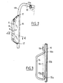
- Figure 3 is a perspective view showing the hinge support of the adjustable bead.
- FIG. 4 is a cross-sectional view of a lateral bead along 4-4 of FIG. 1 or of FIG. 2.
- FIG. 1 we see a motor vehicle seat generally designated by the reference 1.
- This seat has a seat 2 and a backrest 3 whose shape is designed to provide the best possible comfort to the user.
- the seat 2 has lateral beads 4 projecting from the surface of the seat.
- the backrest 3 also includes lateral bulges 6 at its upper part which can serve as a headrest as well as two adjustable lateral bulges 7 according to the invention over most of its height, on either side of an area.
- lumbar support 5 whose curvature can be adjusted in the direction of arrow 8, depending on the morphology of the user.
- the adjustment of the curvature of the lumbar support zone 5 can be obtained for example by means of an inflatable envelope placed under the lining of the seat 1.
- the adjustment of the lateral beads 7 in the transverse direction of the seat, according to the size of the user, can be obtained by pivoting these lateral beads, according to the arrows 9, as will be described later.
- the lower part of the backrest which plays a large part in the comfort of the user can therefore be adapted to the morphology and build of this user, both thanks to a known adjustment device for the lumbar support area. and to the transverse adjustment device for the side beads 7, as will be described later.
- FIGS. 2, 3 and 4 we see a part of the tubular frame of the backrest 3 of the seat 1, located on a lateral side of this seat comprising an adjustable bead 7.
- the tubular frame 10 comprises a transverse branch 10a directed along the width of the seat and a branch 10b substantially perpendicular to the transverse branch 10a, inclined according to the inclination of the backrest 3 and arranged in a longitudinal plane of the seat generally corresponding to a vertical plane longitudinal direction with respect to the vehicle.
- the lateral bead 7 comprises a rigid internal housing 11 constituted by a hollow shell made of sheet metal or of plastic material and giving its shape to the lateral bead 7.
- the housing 11 is coated on the outside with a lining flexible 12 constituted for example by a foam body covered by the fabric of the seat.
- FIG. 2 there is shown only the housing 11, excluding the gasket 12.
- the housing 11 is pivotally mounted about a hinge pin 13 parallel to the branch 10b of the frame 10, the axis 13 being located in a longitudinal plane parallel to the vertical median plane P of the seat 1.
- the pivoting of the housing 11 is therefore accompanied by a transverse displacement shown by the arrow 14 in FIG. 2.
- the articulation axis 13 is materialized by two ends of shafts 15a and 15b constituted by the ends of a stirrup 15 made of rigid steel wire welded at 16a and 16b on the branch 10b of the frame and arranged in the longitudinal plane of the seat containing the axis of articulation 13 and the axis of the tubular branch 10b.
- the housing 11 includes, at each of its ends, a housing 17 in which one of the ends of the shafts 15a or 15b engages in mounting, to constitute a hinge for articulation.
- the stirrup 15 constituting an articulation support is disposed inside the housing 11 which is itself pivotally mounted on this articulation support 15.
- a support plate 18 is also mounted inside the housing 11 and disposed substantially along the longitudinal plane passing through the hinge axis 13.
- the support plate 18 constituted for example by a sheet metal has at its ends profiled assembly parts 19 and 20 ensuring the clipping of the support plate 18 on the upper part of the stirrup 15 and on the branch 10b of the frame 10, respectively.
- the support plate 18 is thus rigidly fixed on the frame of the seat 1.
- the housing 11 contains an inflatable flexible envelope 21 which may be constituted for example by a rubber membrane.
- the envelope 21 is interposed between the inner surface of the housing 11 and one of the faces of the support plate 18, on the side of the bead 7 located towards the inside of the seat 1.
- the face of the plate 18 in contact with the envelope 21 is directed towards the lateral bead 7 located on the opposite side of the seat 1.
- a set of return springs such as 22, is interposed between the other face of the support plate 18, that is to say the face of this support plate directed towards the outside of the seat, and the inner surface of the housing 11 facing it.
- the inflatable bag 21 is connected by a flexible pipe not shown to a manual inflation means such as a pear or to electro-pneumatic means which can be actuated by the user to ensure inflation and adjustable expansion of the bag 21 .
- a manual inflation means such as a pear or to electro-pneumatic means which can be actuated by the user to ensure inflation and adjustable expansion of the bag 21 .
- Such means of inflating a flexible envelope associated with a vehicle seat are well known, and used for example in the case of an inflatable envelope or pocket disposed in the lumbar support part of the seat as indicated above.
- the lateral beads are then in their position of maximum separation. This position corresponds to the seat adjustment position for heavy users.
- the pockets 21 bearing on one of the faces of the plates 18 cause the corresponding housing 11 to rotate about its pivot axis 13. Simultaneously, the springs 22 are compressed.
- the inflation of the pockets and the pivoting of the lateral beads towards the interior is continued until the position of maximum comfort is obtained by the user.
- the lateral beads are then in balance under the antagonistic effect of the inflatable pockets and the springs.
- the inflation circuits of the two lateral beads of the seat must be completely independent, so as to avoid, when the body of the user is supported on one of the beads, for example in a bend, the transfer of air from the inflatable pocket of this bead to the inflatable pocket of the opposite bead. This would indeed have harmful consequences on the maintenance and comfort of the user.
- the seat according to the invention has the advantage of having adjustable lateral beads according to the body size of the occupant of the seat, these beads having however a stable and constant geometric shape during the adjustments. Adjusting the seat while providing effective support for the user, therefore does not change the general shape and style of the seat.
- boxes or support plates of a shape different from that which has been described in particular a housing consisting of two parts which can be assembled to one another, for example by clipping, gluing,. . . , to facilitate the mounting of the internal structure of the bead, these elements being able to be mounted on the seat frame, in a manner different from that which has been described.
- the articulation support can consist of a stamped sheet metal part, in place of a rigid metal wire structure. The articulation of the housing on the frame by means of the articulation support can be carried out in a different manner from that which has been described.
- This reminder can be provided by a completely waterproof pocket containing a certain amount of air and interposed between the support plate and the inner surface of the housing.
- the devices for inflating the pockets for actuating the side beads can be of any type, depending on the desired result.
- the motor vehicle seat according to the invention may include adjustable lateral beads associated with both its seat part and its back.
- the seat according to the invention can combine adjustable lateral bulges with other means for adjusting the seat according to the morphology or body size of the user, such as lumbar adjustment means or adjustable support devices for legs of the user.
Landscapes
- Engineering & Computer Science (AREA)
- Aviation & Aerospace Engineering (AREA)
- Transportation (AREA)
- Mechanical Engineering (AREA)
- Seats For Vehicles (AREA)
Claims (9)
- Kraftfahrzeugsitz, der eine starre Bewehrung (10) und einen biegsamen Überzug aufweist, der die Bewehrung abdeckt und mindestens zwei seitliche Verdickungen (7), welche in der Querrichtung des Sitzes einstellbar sind, wobei jede der seitlichen Verdickungen (7) aufweist:- eine Gelenkunterstützung (15), die starr auf der Bewehrung (10) befestigt ist und eine Drehachse (13) definiert, die sich in einer seitlichen im wesentlichen longitudinalen Ebene bezüglich dem Sitz (1) befindet;- eine Stützplatte (18), die starr auf der Bewehrung (10) gemäß einer seitlichen im wesentlichen longitudinalen Ebene befestigt ist;- eine aufblasbare Tasche (21) dadurch gekennzeichnet, daß die seitlichen Verdickungen außerdem aufweisen;- ein Gehäuse (11) das eine Schale bildet und durch die Garnitur bedeckt ist, die die eigentliche Verdickung (7) bildet um der Verdickung eine Form zu geben, die im wesentlichen unabhängig von ihrer Einstellbarkeit ist, und daß in der Querrichtung (14) des Sitzes (1) gelenkig auf der Drehachse (13) montiert ist, wobei die Stützplatte (18) mindestens teilweise innerhalb dem Gehäuse (11) angeordnet ist, wobei die aufblasbare Tasche (21) sich innerhalb dem Gehäuse (11) befindet, und zwar zwischen der inneren Wand des Gehäuses (11) und der Stützplatte (18) an der inneren Seite des Sitzes (1) undmindestens einer elastischen Rückrufvorrichtung (22), die zwischen der inneren Wand des Gehäuses (11) und der Stützplatte (18) an der äußeren Seite des Sitzes (1) angeordnet ist.
- Kraftfahrzeugsitz nach Anspruch 1, dadurch gekennzeichnet, daß die Stützplatte (18) mit einem ihrer Enden auf einem Stab (10b) der Bewährung (10) und mit ihrem anderen Ende auf einen Teil der Gelenkunterstützung (15) befestigt ist.
- Kraftfahrzeugsitz nach Anspruch 2, dadurch gekennzeichnet, daß die Stützplatte (18) durch Klippen der Bewährung (10) und auf der Gelenkunterstüzung (15) befestigt ist.
- Kraftfahrzeugsitz nach einem der vorhegehenden Ansprüche 1 bis 3, dadurch gekennzeichnet, daß die Gelenkunterstüzung (15) durch eine starre Struktur gebildet wird, die aus einem gebogenen Metalldraht besteht, der durch Schweißung auf einer Welle (10b) der Bewehrung (10) befestigt ist, und zwei ausgerichteten Wellenenden (15a, 15b), die parallel an der Bewehrung (10) sind.
- Kraftfahrzeugsitz nach einem der vorhergehenden Ansprüche 1 bis 4, dadurch gekennzeichnet, daß die aufblasbare Tasche (21) für ihres Aufblasen mit einer manuellen Vorrichtung sowie einer Birne verbunden ist.
- Kraftfahrzeugsitz nach einem der vorhergehenden Ansprüche 1 bis 4, dadurch gekennzeichnet, daß die aufblasbare Tasche (21) für ihres Aufblasen mit einer elekropneumatischen Vorrichtung, sowie einer Motorpumpe verbunden ist.
- Kraftfahrzeugsitz nach einem der vorhergehenden Ansprüche 1 bis 6, dadurch gekennzeichnet, daß das Gehäuse (11) aus zwei Halb-Gehäusen besteht, die Montage-Einrichtungen aufweisen.
- Kraftfahrzeugsitz nach einem der vorhergehenden Ansprüche 1 bis 7, der ein Sitzteil (2) und Rücken (3) aufweist, dadurch gekennzeichnet, daß er einstellbaren seitlichen Verdickungen (7) ausschließlich auf den Seiten des Rückens (3) aufweist.
- Kraftfahrzeugsitz nach einem der vorhergehenden Ansprüche 1 bis 7, der einen Sitzteil (2) und einen Rücken (3) aufweist, dadurch gekennzeichnet, daß er einstellbare seitliche Verdickungen sowohl auf den Seiten seines Sitzteiles (2) als auch auf den Seiten des Rückens (3) aufweist.
Applications Claiming Priority (2)
| Application Number | Priority Date | Filing Date | Title |
|---|---|---|---|
| FR8806801A FR2631590B1 (fr) | 1988-05-20 | 1988-05-20 | Siege de vehicule automobile comportant des bourrelets lateraux reglables |
| FR8806801 | 1988-05-20 |
Publications (2)
| Publication Number | Publication Date |
|---|---|
| EP0343025A1 EP0343025A1 (de) | 1989-11-23 |
| EP0343025B1 true EP0343025B1 (de) | 1992-12-30 |
Family
ID=9366500
Family Applications (1)
| Application Number | Title | Priority Date | Filing Date |
|---|---|---|---|
| EP89401110A Expired - Lifetime EP0343025B1 (de) | 1988-05-20 | 1989-04-20 | Kraftfahrzeugsitz mit verstellbaren Seitenwulsten |
Country Status (3)
| Country | Link |
|---|---|
| EP (1) | EP0343025B1 (de) |
| DE (1) | DE68904114T2 (de) |
| FR (1) | FR2631590B1 (de) |
Cited By (1)
| Publication number | Priority date | Publication date | Assignee | Title |
|---|---|---|---|---|
| US10166901B2 (en) | 2016-02-24 | 2019-01-01 | GM Global Technology Operations LLC | Seat for a motor vehicle |
Families Citing this family (15)
| Publication number | Priority date | Publication date | Assignee | Title |
|---|---|---|---|---|
| US5437498A (en) * | 1994-02-22 | 1995-08-01 | Hoover Universal, Inc. | Vehicle seat with side bolster reinforcement |
| FR2761310B1 (fr) * | 1997-03-25 | 1999-06-11 | Peugeot | Siege pour vehicule automobile comprenant des bourrelets lateraux de rigidite automatiquement reglable |
| DE102004014881B4 (de) * | 2004-03-26 | 2008-02-28 | Recaro Gmbh & Co. Kg | Fahrzeugsitz mit Seitenwangen |
| DE102005024774B4 (de) | 2005-05-31 | 2018-07-12 | Bayerische Motoren Werke Aktiengesellschaft | Fahrzeugsitz mit Lehnenbreitenverstellung und integriertem Sitz-Airbag |
| JP4459948B2 (ja) * | 2006-12-11 | 2010-04-28 | 本田技研工業株式会社 | 車両用シート |
| DE102007009891A1 (de) * | 2007-02-28 | 2008-09-04 | L & P Swiss Holding Company | Vorrichtung und Verfahren zum Verstellen einer Seitenwange eines Sitzes |
| DE102008028353A1 (de) * | 2008-06-13 | 2009-12-17 | Dr. Ing. H.C. F. Porsche Aktiengesellschaft | Fahrzeugsitz |
| DE102009012620A1 (de) * | 2009-03-11 | 2010-09-16 | GM Global Technology Operations, Inc., Detroit | Fahrzeugsitz mit einer konturveränderbaren Stützfläche |
| DE102012017823B4 (de) * | 2012-09-08 | 2014-09-18 | Faurecia Autositze Gmbh | Verstellvorrichtung für Kraftfahrzeugsitze |
| DE102014002211B4 (de) * | 2014-02-20 | 2018-05-03 | Grammer Aktiengesellschaft | Fahrzeugsitz mit formveränderbaren Seitenwangen |
| DE102014008818A1 (de) | 2014-06-17 | 2015-12-17 | GM Global Technology Operations LLC (n. d. Ges. d. Staates Delaware) | Sitz für ein Kraftfahrzeug |
| DE102019114089A1 (de) * | 2019-05-27 | 2020-12-03 | Faurecia Autositze Gmbh | Pneumatische Einstelleinrichtung für eine Seitenwange eines Fahrzeugsitzes |
| FR3102114B1 (fr) | 2019-10-17 | 2021-09-10 | Psa Automobiles Sa | Siège pour un véhicule automobile avec un dossier comprenant des bourrelets latéraux ajustables |
| DE102020103243A1 (de) | 2020-02-10 | 2021-08-12 | Faurecia Autositze Gmbh | Pneumatische Einstelleinrichtung für eine Seitenwange eines Fahrzeugsitzes |
| CN113525190A (zh) * | 2021-08-24 | 2021-10-22 | 艾福迈汽车系统(上海)有限公司 | 一种基于图形识别技术的汽车座椅侧翼支撑调整方法 |
Family Cites Families (5)
| Publication number | Priority date | Publication date | Assignee | Title |
|---|---|---|---|---|
| JPS57205238A (en) * | 1981-06-15 | 1982-12-16 | Tachikawa Spring Co Ltd | Seat |
| DE3337910A1 (de) * | 1983-10-19 | 1985-05-09 | Keiper Recaro GmbH & Co, 5630 Remscheid | Fahrzeugsitz |
| JPS60206741A (ja) * | 1984-03-30 | 1985-10-18 | Nissan Shatai Co Ltd | 自動車用シ−トのサイドサポ−ト |
| US4920591A (en) * | 1985-07-16 | 1990-05-01 | Hiroshi Sekido | Air support for chair and method for manufacturing chair utilizing the air support |
| FR2592844B1 (fr) * | 1986-01-10 | 1990-07-20 | Renault | Appui a poche gonflable pour sieges de vehicules automobiles |
-
1988
- 1988-05-20 FR FR8806801A patent/FR2631590B1/fr not_active Expired - Fee Related
-
1989
- 1989-04-20 EP EP89401110A patent/EP0343025B1/de not_active Expired - Lifetime
- 1989-04-20 DE DE8989401110T patent/DE68904114T2/de not_active Expired - Fee Related
Cited By (1)
| Publication number | Priority date | Publication date | Assignee | Title |
|---|---|---|---|---|
| US10166901B2 (en) | 2016-02-24 | 2019-01-01 | GM Global Technology Operations LLC | Seat for a motor vehicle |
Also Published As
| Publication number | Publication date |
|---|---|
| DE68904114D1 (de) | 1993-02-11 |
| EP0343025A1 (de) | 1989-11-23 |
| DE68904114T2 (de) | 1993-05-27 |
| FR2631590A1 (fr) | 1989-11-24 |
| FR2631590B1 (fr) | 1990-08-24 |
Similar Documents
| Publication | Publication Date | Title |
|---|---|---|
| EP0343025B1 (de) | Kraftfahrzeugsitz mit verstellbaren Seitenwulsten | |
| EP0318355B1 (de) | Umlegvorrichtung für die Seitenkanten eines Sitzes und Schalensitz für Kraftfahrzeuge oder ähnliches, welcher eine solche Vorrichtung aufweist | |
| FR2893280A1 (fr) | Systeme pour regler automatiquement des sieges, notamment des sieges de vehicules. | |
| EP2091778A1 (de) | Kopfstütze für autositz und mit dieser kopfstütze ausgestatteter autositz | |
| EP0949115B1 (de) | Kraftfahrzeugrücksitz mit Vorrichtung zur Verhinderung des Abtauchens | |
| EP0241969B1 (de) | Sessel für ein Fahrzeug, insbesondere Kraftfahrzeug | |
| FR2761310A1 (fr) | Siege pour vehicule automobile comprenant des bourrelets lateraux de rigidite automatiquement reglable | |
| EP1048515B1 (de) | Konsolenarmlehne für einen Kraftfahrzeuginnenraum | |
| FR2755074A1 (fr) | Dispositif de reglage en hauteur d'un accoudoir et accoudoir de vehicule automobile equipe d'un tel dispositif de reglage | |
| EP1995126B1 (de) | Vorrichtung zum Einbau eines Airbagsets im Rücksitz eines Kraftfahrzeugs | |
| FR2844489A1 (fr) | Siege de vehicule dote d'un dispositif de protection du cou en cas de choc arriere | |
| FR2727066A1 (fr) | Siege a reglage pneumatique et vehicule automobile equipe de ce siege | |
| FR2812594A1 (fr) | Siege de vehicule comportant un coussin d'appui lateral | |
| FR2710012A1 (fr) | Siège pour véhicule automobile adaptable à la morphologie d'un enfant. | |
| FR3144581A1 (fr) | Dossier de siège de véhicule et siège de véhicule comprenant un tel dossier | |
| FR2546826A1 (fr) | Siege pour vehicule automobile | |
| EP0045679A1 (de) | Umwandelbarer Sitz | |
| FR2521411A1 (fr) | Armature de siege | |
| FR2829975A1 (fr) | Dispositif de siege | |
| FR2806045A1 (fr) | Vehicule comportant un siege dote d'un dossier rabattable | |
| FR2804640A1 (fr) | Siege de vehicule dote d'un accoudoir pivotant, et dispositif d'appui pour un tel siege | |
| EP1738952B1 (de) | Fahrzeug mit einer verschiebbaren Sitzbank und auf dieser Sitzbank schwenkbar montierten Seitenelementen | |
| EP4392291B1 (de) | Fahrzeugsitz mit einem bordsicherheitssystem | |
| EP0284454A1 (de) | Trapezgurt für Windsurfer | |
| FR2867725A1 (fr) | Siege de vehicule automobile dote d'un dispositif de protection du cou en cas de choc arriere |
Legal Events
| Date | Code | Title | Description |
|---|---|---|---|
| PUAI | Public reference made under article 153(3) epc to a published international application that has entered the european phase |
Free format text: ORIGINAL CODE: 0009012 |
|
| AK | Designated contracting states |
Kind code of ref document: A1 Designated state(s): DE GB IT |
|
| 17P | Request for examination filed |
Effective date: 19891019 |
|
| 17Q | First examination report despatched |
Effective date: 19910909 |
|
| GRAA | (expected) grant |
Free format text: ORIGINAL CODE: 0009210 |
|
| AK | Designated contracting states |
Kind code of ref document: B1 Designated state(s): DE GB IT |
|
| REF | Corresponds to: |
Ref document number: 68904114 Country of ref document: DE Date of ref document: 19930211 |
|
| GBT | Gb: translation of ep patent filed (gb section 77(6)(a)/1977) |
Effective date: 19920205 |
|
| ITF | It: translation for a ep patent filed | ||
| PGFP | Annual fee paid to national office [announced via postgrant information from national office to epo] |
Ref country code: DE Payment date: 19930331 Year of fee payment: 5 |
|
| PGFP | Annual fee paid to national office [announced via postgrant information from national office to epo] |
Ref country code: GB Payment date: 19930413 Year of fee payment: 5 |
|
| PLBE | No opposition filed within time limit |
Free format text: ORIGINAL CODE: 0009261 |
|
| STAA | Information on the status of an ep patent application or granted ep patent |
Free format text: STATUS: NO OPPOSITION FILED WITHIN TIME LIMIT |
|
| 26N | No opposition filed | ||
| PG25 | Lapsed in a contracting state [announced via postgrant information from national office to epo] |
Ref country code: GB Effective date: 19940420 |
|
| GBPC | Gb: european patent ceased through non-payment of renewal fee |
Effective date: 19940420 |
|
| PG25 | Lapsed in a contracting state [announced via postgrant information from national office to epo] |
Ref country code: DE Effective date: 19950103 |
|
| PG25 | Lapsed in a contracting state [announced via postgrant information from national office to epo] |
Ref country code: IT Free format text: LAPSE BECAUSE OF NON-PAYMENT OF DUE FEES;WARNING: LAPSES OF ITALIAN PATENTS WITH EFFECTIVE DATE BEFORE 2007 MAY HAVE OCCURRED AT ANY TIME BEFORE 2007. THE CORRECT EFFECTIVE DATE MAY BE DIFFERENT FROM THE ONE RECORDED. Effective date: 20050420 |