EP0343003A2 - Auftraggerät für fliessbares Material - Google Patents
Auftraggerät für fliessbares Material Download PDFInfo
- Publication number
- EP0343003A2 EP0343003A2 EP89305095A EP89305095A EP0343003A2 EP 0343003 A2 EP0343003 A2 EP 0343003A2 EP 89305095 A EP89305095 A EP 89305095A EP 89305095 A EP89305095 A EP 89305095A EP 0343003 A2 EP0343003 A2 EP 0343003A2
- Authority
- EP
- European Patent Office
- Prior art keywords
- plunger
- rack
- cartridge
- dispenser
- pinion
- Prior art date
- Legal status (The legal status is an assumption and is not a legal conclusion. Google has not performed a legal analysis and makes no representation as to the accuracy of the status listed.)
- Withdrawn
Links
Images


Classifications
-
- B—PERFORMING OPERATIONS; TRANSPORTING
- B05—SPRAYING OR ATOMISING IN GENERAL; APPLYING FLUENT MATERIALS TO SURFACES, IN GENERAL
- B05C—APPARATUS FOR APPLYING FLUENT MATERIALS TO SURFACES, IN GENERAL
- B05C17/00—Hand tools or apparatus using hand held tools, for applying liquids or other fluent materials to, for spreading applied liquids or other fluent materials on, or for partially removing applied liquids or other fluent materials from, surfaces
- B05C17/005—Hand tools or apparatus using hand held tools, for applying liquids or other fluent materials to, for spreading applied liquids or other fluent materials on, or for partially removing applied liquids or other fluent materials from, surfaces for discharging material from a reservoir or container located in or on the hand tool through an outlet orifice by pressure without using surface contacting members like pads or brushes
- B05C17/01—Hand tools or apparatus using hand held tools, for applying liquids or other fluent materials to, for spreading applied liquids or other fluent materials on, or for partially removing applied liquids or other fluent materials from, surfaces for discharging material from a reservoir or container located in or on the hand tool through an outlet orifice by pressure without using surface contacting members like pads or brushes with manually mechanically or electrically actuated piston or the like
- B05C17/0103—Hand tools or apparatus using hand held tools, for applying liquids or other fluent materials to, for spreading applied liquids or other fluent materials on, or for partially removing applied liquids or other fluent materials from, surfaces for discharging material from a reservoir or container located in or on the hand tool through an outlet orifice by pressure without using surface contacting members like pads or brushes with manually mechanically or electrically actuated piston or the like with electrically actuated piston or the like
-
- Y—GENERAL TAGGING OF NEW TECHNOLOGICAL DEVELOPMENTS; GENERAL TAGGING OF CROSS-SECTIONAL TECHNOLOGIES SPANNING OVER SEVERAL SECTIONS OF THE IPC; TECHNICAL SUBJECTS COVERED BY FORMER USPC CROSS-REFERENCE ART COLLECTIONS [XRACs] AND DIGESTS
- Y10—TECHNICAL SUBJECTS COVERED BY FORMER USPC
- Y10T—TECHNICAL SUBJECTS COVERED BY FORMER US CLASSIFICATION
- Y10T74/00—Machine element or mechanism
- Y10T74/18—Mechanical movements
- Y10T74/18568—Reciprocating or oscillating to or from alternating rotary
- Y10T74/188—Reciprocating or oscillating to or from alternating rotary including spur gear
- Y10T74/18808—Reciprocating or oscillating to or from alternating rotary including spur gear with rack
Definitions
- the invention relates to a dispenser for flowable material, particularly a mastic-type material which is used in caulking or sealing.
- a dispenser for dispensing a flowable material from a cartridge comprising a manual holder for the cartridge and a plunger for forcing material from the cartridge on actuation of the plunger characterized by a motor drive for actuating the plunger to move in one direction to dispense material and by means to disengage the motor drive and plunger whereby manual return of the plunger in a direction opposite to the one direction is effected.
- the motor drive may comprise an electric motor. This provides for a relatively simple yet efficient drive for the plunger.
- the plunger may comprise a rack and the motor drive may comprise a pinion which engages the rack for moving same in the one direction.
- a rack and pinion drive such as this provides a relatively simple yet positive drive.
- the motor may be driven by battery means housed in a handgrip of the holder. This provides a compact dispenser device.
- the protective device may comprise a flexible strip of substantially the same width as the rack, for example a flexible metal strip, such as strip steel, suitably stainless.
- the disengaging means may comprise a part of the holder which may carry the pinion and which may be hinged to a further part of the holder. This provides for a relatively simple device whereby when the one part is pivoted away from the other about the hinge, the pinion is lifted off the rack.
- a manual clutch device operable to disengage the rack and pinion.
- the motor may be adapted to release pressure in the one direction at the termination of a dispensing stroke. This provides that sealant is prevented from oozing out of a cartridge in use, after a dispensing step has been terminated.
- a flowable material such as a mastic sealant from a cartridge 2
- a motor device 5 for actuating the plunger 4 to move in one direction to dispense material
- means 6 to disengage the motor drive 5 and plunger 4, whereby manual return of the plunger 4 in a direction opposite to the one direction is effected.
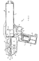
- the dispenser 1 shown is suitable for dispensing or extruding a sealant or any other product contained in standard 5cm x 22cm or 25cm long cartridges.
- the dispenser 1 has two holding points in the form of a handle 7 and a barrel grip 8 and is operated by means of a trigger switch 9.
- a removable, replaceable battery is inserted in the lower portion (as viewed) of the handle, for example secondary cells 10, suitably three in the embodiment.
- the cells 10 provide a direct electric current to the motor 11 via a plunger switch 12 and a reversible speed control switch 13.
- Mechanical power is then transmitted via a compact gear train 14 to a final drive consisting of a rack 15 and pinion 16.
- the rack 15 is guarded against contamination by foreign particles by means of a strip of material 17 which passes over the top of the pinion, inside the device 1.
- the reduction through the gears is in the order of 1024:1.
- the cartridge 2 is received in the chamber 3 by the dispenser 1 having an upper (as viewed) part 18 which is hinged at 19 to the lower part 20, which upper part 18 carries the plunger 4 which itself carries the rack 15, and a final gear 21 carrying the pinion 16 so that when the upper part 18 is pivoted away from the lower part 20, the drive to the rack 15 is disengaged and the plunger 4 can be returned to an initial starting position (to the left in Figures 1,2) to facilitate the insertion of a fresh cartridge and the initiation of fresh dispensing operations.
- the two parts 18,20 of the dispenser are held together in the closed position by a push bar lock 22, which is pushed forward (to the right as viewed) to open the chamber 3 for ejection of a used or spent cartridge 2.
- the trigger 9 is operated to start the motor 11, which in turn operates the gears 14,21 to turn the pinion 16 which acts on the rack 15 to drive the piston 4 in one direction, the dispensing direction, so that a buffer, nose or plate 23 on the one end sears on the cartridge 2 to compress same and to extrude sealant from a nozzle.
- the chamber 3 is opened as described above, and the plunger 4 is withdrawn manually in the opposite direction to the one direction to the left as the rack 15 and pinion 16 are disengaged.
- the plunger 4 slides in mounting blocks 23 having bores of complementary shape.
- the motor 11 may be of variable speed and reversible via switch 13 so that at the end of a stroke to extrude sealant, depressurization is facilitated after each extrusion operation so that the mastic material is prevented from oozing out of the nozzle.
- the reversible speed control switch 13 for the motor is incorporated to initiate such depressurization.
- the dispenser 100 is similar to the first one in that it has a plunger 4 which is driven by a battery operated electric motor through suitable gearing 5 in one direction (to the right in Figure 4) to dispense sealant from a cartridge, this again having a circular cross-section with a chordal slice removed to provide a flat (in use) upper surface which is in the form of a rack 15 which is protected by a flexible metal strip 17 secured to the plunger 4 at opposite ends and overlying a pinion 16 engaging the teeth of the rack 15.
- the plunger 4 is withdrawn manually to allow replacement of a spent cartridge with a fully charged one.
- a disengagement means 6 which comprises a toothed clutch part 101 on the pinion 16 mounted on an axle 102 on which there is also a coil spring 103.
- the spring 103 is between the toothed clutch part 101 and a second toothed clutch part 104 carried axially by a final drive gear 21 of a gear train 5 through which the motor 11 operates to drive the rack 15 in the one direction.
- toggle or wish-bone kind of device 106 which has intermediate bosses 105 mounted for pivoting in a lug 107 of a carrier 108 which has mounting trunnions for the end of the axle 102, and for axles 109,110 which carry other gears 5 of the gear train, one of which is driven by the motor 11.
- carrier 111 There is a similar opposite carrier 111 to make a composite unit.
- One end of the toggle device 106 has flat bearing surfaces 112 which bear on the gear wheel 21.
- the other end has an inclined cam follower surface 113 which is in sliding engagement with a wedge-shaped or inclined cam surface 114 carried on the side of a trigger switch 9 of the dispenser 1, the switch 9 being operable to start the motor 11 to drive the rack 15.
- the trigger 9 projects to its maximum extent so that the two surfaces 113 and 114 are virtually disengaged.
- the spring 103 acts to push the gear 21 to the right as viewed, so that the clutch parts 101 and 104 are disengaged.
- This in turn causes the device 106 to be pivoted to the right about the bosses 105.
- the trigger 9 is squeezed or depressed. This action forces the cam surface 114 towards the cam follower 113 so that the free space between the lower part of the device 106 and the trigger 9 is effectively lessened as the cam incline "increases".
- the trigger 9 When it is desired to cease dispensing sealant, the trigger 9 is released. This causes it to move to its initial position under spring (not shown) pressure, so moving the inclined surfaces 113,114 apart. The pressure on the spring 103 is thus released, so it moves the clutch parts 101,104 apart so they are disengaged, and this in turn pivots the device 106 clockwise (as viewed) to the starting position. The plunger can then be retracted manually using handgrip 115, and a used or spent cartridge can be removed and replaced.
- the batteries are housed in the handgrip 7 as before.
- the plunger piston 4 passes through complementarily shaped bearing bosses or parts 116,117 in the dispenser body, there being a screw thread 118 on the forward boss 117 through which the plunger 4 projects and to which the chamber 3 for the cartridge is secured by a nut 119, the buffer 23 being on the side of the nut 119 remote from the gears 5.
- the chamber 3 is cylindrical and has a screw nozzle 115 on the distal end which is removable so that cartridges can be mounted in and removed from the dispenser.
- the second embodiment is thus similar to the first, but the act of engaging and disengaging the drive to the rack is accomplished by simply operating the trigger 9.
Landscapes
- Engineering & Computer Science (AREA)
- Mechanical Engineering (AREA)
- Coating Apparatus (AREA)
Applications Claiming Priority (2)
| Application Number | Priority Date | Filing Date | Title |
|---|---|---|---|
| GB8812039 | 1988-05-20 | ||
| GB888812039A GB8812039D0 (en) | 1988-05-20 | 1988-05-20 | Cordless cartridge gun |
Publications (2)
| Publication Number | Publication Date |
|---|---|
| EP0343003A2 true EP0343003A2 (de) | 1989-11-23 |
| EP0343003A3 EP0343003A3 (de) | 1991-03-13 |
Family
ID=10637281
Family Applications (1)
| Application Number | Title | Priority Date | Filing Date |
|---|---|---|---|
| EP19890305095 Withdrawn EP0343003A3 (de) | 1988-05-20 | 1989-05-19 | Auftraggerät für fliessbares Material |
Country Status (3)
| Country | Link |
|---|---|
| US (1) | US4986454A (de) |
| EP (1) | EP0343003A3 (de) |
| GB (1) | GB8812039D0 (de) |
Cited By (10)
| Publication number | Priority date | Publication date | Assignee | Title |
|---|---|---|---|---|
| WO1993001124A1 (en) * | 1991-07-08 | 1993-01-21 | Cathcart John C Sr | Automatic tuckpointing gun |
| US5228605A (en) * | 1988-12-30 | 1993-07-20 | Robert Bosch Gmbh | Automatically guidable hand tool for applying free-flowing pasty materials to a base |
| EP0563486A1 (de) * | 1992-03-30 | 1993-10-06 | Immuno France S.A.R.L. | Vorrichtung zum Auftragen einen pharmazeutischen oder kosmetischen Zusammensetzung |
| US5353971A (en) * | 1993-05-10 | 1994-10-11 | Bijan Vaziri | Electric caulking gun apparatus |
| WO1997048498A3 (fr) * | 1996-06-14 | 1998-04-09 | Andre Cossette | Pistolet applicateur a produit scellant |
| US5775539A (en) * | 1995-05-05 | 1998-07-07 | Bates; Darryle E. | Electrically operated material dispensing gun and method |
| US6089407A (en) * | 1998-12-31 | 2000-07-18 | Dispensing Technologies International Inc. | Electrically powered fluid-dispersing apparatus and a method particularly adapted for hand gun operation |
| KR20030068665A (ko) * | 2002-02-15 | 2003-08-25 | 문성훈 | 전동식 실리콘 분사기 |
| US6889872B2 (en) | 2002-06-28 | 2005-05-10 | Meritool, L.L.C. | Electric two-part material dispenser |
| EP2564942A3 (de) * | 2011-09-02 | 2014-04-09 | Milwaukee Electric Tool Corporation | Elektrisches Ausgabewerkzeug |
Families Citing this family (22)
| Publication number | Priority date | Publication date | Assignee | Title |
|---|---|---|---|---|
| US5295614A (en) * | 1992-12-22 | 1994-03-22 | Chang Peter J Y | Double reduction gear for dispensing gun |
| US5341958A (en) * | 1992-12-24 | 1994-08-30 | Bayat John J | Power operated caulking tool |
| USD361247S (en) | 1994-07-18 | 1995-08-15 | Wagner Spray Tech Corporation | Powered caulker |
| US5450988A (en) * | 1994-07-18 | 1995-09-19 | Wagner Spray Tech Corporation | Powered caulking gun |
| US6062428A (en) * | 1998-07-29 | 2000-05-16 | Callahan; Sean P. | Viscid product dispenser |
| US6123235A (en) * | 1999-05-21 | 2000-09-26 | Hsu; Chih-Hua | Caulking gun |
| US6527779B1 (en) * | 2000-07-10 | 2003-03-04 | Endotex Interventional Systems, Inc. | Stent delivery device |
| US6488180B1 (en) | 2001-04-02 | 2002-12-03 | John Jahangir Bayat | Power operated caulking gun |
| US7971758B2 (en) * | 2005-11-10 | 2011-07-05 | Black & Decker Inc. | Caulk gun |
| US8020727B2 (en) * | 2006-10-18 | 2011-09-20 | Meritool Llc | Powered dispensing tool and method for controlling same |
| DE102007000502A1 (de) * | 2007-10-15 | 2009-04-16 | Hilti Aktiengesellschaft | Auspressvorrichtung |
| CN101596510B (zh) * | 2009-07-09 | 2011-11-09 | 高益松 | 一种发泡剂压力罐的使用工具 |
| US20110182652A1 (en) * | 2010-01-22 | 2011-07-28 | Hannah Chung | Wearable Sanitizing Gel Dispenser, Kit, and Associated Methods |
| CN203711286U (zh) * | 2010-11-15 | 2014-07-16 | 密尔沃基电动工具公司 | 电动分配工具 |
| USD659492S1 (en) | 2011-04-04 | 2012-05-15 | Sabodish Kenneth R | Caulking device |
| JP5918575B2 (ja) * | 2012-03-08 | 2016-05-18 | 株式会社マキタ | コーキングガン |
| CN211660579U (zh) | 2019-11-13 | 2020-10-13 | 创科无线普通合伙 | 压力清洗机 |
| DE102020205316A1 (de) | 2020-04-27 | 2021-10-28 | Festool Gmbh | Vorsatzgerät und Verfahren |
| DE102020205311A1 (de) | 2020-04-27 | 2021-10-28 | Festool Gmbh | Flüssigkeitsbehälter-Presse und Verfahren |
| EP4187045A1 (de) | 2020-06-09 | 2023-05-31 | Groupe Refraco Inc. | Mörtelapplikator und mörtelauftragssystem damit |
| US12330179B2 (en) * | 2020-08-26 | 2025-06-17 | Deere &Company | Work vehicle sprayer system and method with pinching nozzle apparatus |
| US12403494B2 (en) | 2020-08-26 | 2025-09-02 | Deere & Company | Work vehicle sprayer system and method with nozzle monitoring |
Family Cites Families (11)
| Publication number | Priority date | Publication date | Assignee | Title |
|---|---|---|---|---|
| USRE26180E (en) * | 1967-04-04 | Dispensing gun | ||
| US3635378A (en) * | 1969-11-24 | 1972-01-18 | Damon Dehart | Applicating devices |
| CH562942A5 (de) * | 1972-06-08 | 1975-06-13 | Blieberger Rudolf | |
| US3799407A (en) * | 1973-04-27 | 1974-03-26 | W Loethen | Semi-solid material dispensing including a power operated scoop |
| US3913799A (en) * | 1974-02-28 | 1975-10-21 | Davis George B Jun | Caulking gun adapter for electric hand drill |
| US3985273A (en) * | 1974-02-28 | 1976-10-12 | Davis George B Jun | Caulking gun adapter for an electric hand drill |
| US4180187A (en) * | 1978-06-30 | 1979-12-25 | Ben Haim Haim | Automatic piston drive mechanism for use in caulking gun |
| JPS59222251A (ja) * | 1983-05-31 | 1984-12-13 | Matsushita Electric Works Ltd | 電動式粘稠剤押出機 |
| JPS6034764A (ja) * | 1983-08-05 | 1985-02-22 | Matsushita Electric Works Ltd | 粘稠剤押出機 |
| DE3418630A1 (de) * | 1984-05-18 | 1985-11-21 | Horst 3000 Hannover Pudwill | Vorrichtung zum verpressen von dichtungsmasse oder dergleichen, insbesondere fugendichtungsmasse |
| AU579292B2 (en) * | 1985-03-26 | 1988-11-17 | Kuka Schweissanlagen & Roboter Gmbh | Rack drive |
-
1988
- 1988-05-20 GB GB888812039A patent/GB8812039D0/en active Pending
-
1989
- 1989-05-19 EP EP19890305095 patent/EP0343003A3/de not_active Withdrawn
- 1989-05-22 US US07/354,774 patent/US4986454A/en not_active Expired - Fee Related
Cited By (12)
| Publication number | Priority date | Publication date | Assignee | Title |
|---|---|---|---|---|
| US5228605A (en) * | 1988-12-30 | 1993-07-20 | Robert Bosch Gmbh | Automatically guidable hand tool for applying free-flowing pasty materials to a base |
| US5246144A (en) * | 1989-12-26 | 1993-09-21 | Cathcart Sr John C | Automatic tuckpointing gun |
| WO1993001124A1 (en) * | 1991-07-08 | 1993-01-21 | Cathcart John C Sr | Automatic tuckpointing gun |
| EP0563486A1 (de) * | 1992-03-30 | 1993-10-06 | Immuno France S.A.R.L. | Vorrichtung zum Auftragen einen pharmazeutischen oder kosmetischen Zusammensetzung |
| US5353971A (en) * | 1993-05-10 | 1994-10-11 | Bijan Vaziri | Electric caulking gun apparatus |
| US5775539A (en) * | 1995-05-05 | 1998-07-07 | Bates; Darryle E. | Electrically operated material dispensing gun and method |
| WO1997048498A3 (fr) * | 1996-06-14 | 1998-04-09 | Andre Cossette | Pistolet applicateur a produit scellant |
| US6089407A (en) * | 1998-12-31 | 2000-07-18 | Dispensing Technologies International Inc. | Electrically powered fluid-dispersing apparatus and a method particularly adapted for hand gun operation |
| KR20030068665A (ko) * | 2002-02-15 | 2003-08-25 | 문성훈 | 전동식 실리콘 분사기 |
| US6889872B2 (en) | 2002-06-28 | 2005-05-10 | Meritool, L.L.C. | Electric two-part material dispenser |
| EP2564942A3 (de) * | 2011-09-02 | 2014-04-09 | Milwaukee Electric Tool Corporation | Elektrisches Ausgabewerkzeug |
| US9039557B2 (en) | 2011-09-02 | 2015-05-26 | Milwaukee Electric Tool Corporation | Powered dispensing tool |
Also Published As
| Publication number | Publication date |
|---|---|
| GB8812039D0 (en) | 1988-06-22 |
| EP0343003A3 (de) | 1991-03-13 |
| US4986454A (en) | 1991-01-22 |
Similar Documents
| Publication | Publication Date | Title |
|---|---|---|
| EP0343003A2 (de) | Auftraggerät für fliessbares Material | |
| US7690530B2 (en) | Dispenser for viscous material | |
| US4264021A (en) | Hand held electric caulking gun | |
| US6540113B2 (en) | Fluid dispenser particularly adapted for hand-held operation | |
| US4273269A (en) | Hand held electric caulking gun | |
| EP2564942B1 (de) | Elektrisches Ausgabewerkzeug | |
| US5501374A (en) | Device for extruding high viscosity fluid having multiple modes of operation | |
| EP2234733B1 (de) | Motorbetriebener roller mit innenzufuhr | |
| US6382466B1 (en) | Device for dispensing flowable materials from a plurality of cartridge assemblies | |
| CA2137404A1 (en) | Dispensing devices for high viscosity compositions | |
| US6089412A (en) | Multipurpose dispenser system | |
| US4249677A (en) | Hand held electric caulking gun | |
| US6981621B2 (en) | Caulking gun | |
| US6938804B2 (en) | Dispensing apparatus | |
| US10912632B2 (en) | Motor-driven dispensing gun for and method of dispensing fluid or semi-fluid material | |
| WO2008080590A1 (en) | Bone cement delivery gun | |
| US4440324A (en) | Cartridge-type dispenser gun | |
| US4253589A (en) | Multi-purpose plastic dispenser | |
| WO2004031069A1 (en) | Dispenser for limiting material extruded after actuation | |
| US20250058348A1 (en) | Motor operated dispensing device with cutting blade | |
| WO2007144434A1 (en) | Disposable dispensing device | |
| US20130037567A1 (en) | Material dispensing system | |
| JP2005097961A (ja) | シーリングガン | |
| JP2001518387A5 (de) | ||
| EP1018375A3 (de) | Handbetätigtes Austraggerät für zähflüssige Masse |
Legal Events
| Date | Code | Title | Description |
|---|---|---|---|
| PUAI | Public reference made under article 153(3) epc to a published international application that has entered the european phase |
Free format text: ORIGINAL CODE: 0009012 |
|
| AK | Designated contracting states |
Kind code of ref document: A2 Designated state(s): AT BE CH DE ES FR GB GR IT LI LU NL SE |
|
| PUAL | Search report despatched |
Free format text: ORIGINAL CODE: 0009013 |
|
| AK | Designated contracting states |
Kind code of ref document: A3 Designated state(s): AT BE CH DE ES FR GB GR IT LI LU NL SE |
|
| STAA | Information on the status of an ep patent application or granted ep patent |
Free format text: STATUS: THE APPLICATION IS DEEMED TO BE WITHDRAWN |
|
| 18D | Application deemed to be withdrawn |
Effective date: 19910914 |