EP0342889B1 - Turbine mit variabler Statorgeometrie - Google Patents
Turbine mit variabler Statorgeometrie Download PDFInfo
- Publication number
- EP0342889B1 EP0342889B1 EP89304869A EP89304869A EP0342889B1 EP 0342889 B1 EP0342889 B1 EP 0342889B1 EP 89304869 A EP89304869 A EP 89304869A EP 89304869 A EP89304869 A EP 89304869A EP 0342889 B1 EP0342889 B1 EP 0342889B1
- Authority
- EP
- European Patent Office
- Prior art keywords
- inlet passageway
- annular
- turbine
- wall member
- wall
- Prior art date
- Legal status (The legal status is an assumption and is not a legal conclusion. Google has not performed a legal analysis and makes no representation as to the accuracy of the status listed.)
- Expired
Links
- 239000003570 air Substances 0.000 description 4
- 238000002485 combustion reaction Methods 0.000 description 3
- 230000000694 effects Effects 0.000 description 3
- 238000007789 sealing Methods 0.000 description 3
- VZSRBBMJRBPUNF-UHFFFAOYSA-N 2-(2,3-dihydro-1H-inden-2-ylamino)-N-[3-oxo-3-(2,4,6,7-tetrahydrotriazolo[4,5-c]pyridin-5-yl)propyl]pyrimidine-5-carboxamide Chemical compound C1C(CC2=CC=CC=C12)NC1=NC=C(C=N1)C(=O)NCCC(N1CC2=C(CC1)NN=N2)=O VZSRBBMJRBPUNF-UHFFFAOYSA-N 0.000 description 1
- 206010023230 Joint stiffness Diseases 0.000 description 1
- NIPNSKYNPDTRPC-UHFFFAOYSA-N N-[2-oxo-2-(2,4,6,7-tetrahydrotriazolo[4,5-c]pyridin-5-yl)ethyl]-2-[[3-(trifluoromethoxy)phenyl]methylamino]pyrimidine-5-carboxamide Chemical compound O=C(CNC(=O)C=1C=NC(=NC=1)NCC1=CC(=CC=C1)OC(F)(F)F)N1CC2=C(CC1)NN=N2 NIPNSKYNPDTRPC-UHFFFAOYSA-N 0.000 description 1
- 229910000831 Steel Inorganic materials 0.000 description 1
- 239000012080 ambient air Substances 0.000 description 1
- 230000006835 compression Effects 0.000 description 1
- 238000007906 compression Methods 0.000 description 1
- 239000000356 contaminant Substances 0.000 description 1
- 230000007423 decrease Effects 0.000 description 1
- 230000003247 decreasing effect Effects 0.000 description 1
- 239000000463 material Substances 0.000 description 1
- 239000010959 steel Substances 0.000 description 1
Images

Classifications
-
- F—MECHANICAL ENGINEERING; LIGHTING; HEATING; WEAPONS; BLASTING
- F01—MACHINES OR ENGINES IN GENERAL; ENGINE PLANTS IN GENERAL; STEAM ENGINES
- F01D—NON-POSITIVE DISPLACEMENT MACHINES OR ENGINES, e.g. STEAM TURBINES
- F01D17/00—Regulating or controlling by varying flow
- F01D17/10—Final actuators
- F01D17/12—Final actuators arranged in stator parts
- F01D17/14—Final actuators arranged in stator parts varying effective cross-sectional area of nozzles or guide conduits
- F01D17/141—Final actuators arranged in stator parts varying effective cross-sectional area of nozzles or guide conduits by means of shiftable members or valves obturating part of the flow path
- F01D17/143—Final actuators arranged in stator parts varying effective cross-sectional area of nozzles or guide conduits by means of shiftable members or valves obturating part of the flow path the shiftable member being a wall, or part thereof of a radial diffuser
-
- F—MECHANICAL ENGINEERING; LIGHTING; HEATING; WEAPONS; BLASTING
- F01—MACHINES OR ENGINES IN GENERAL; ENGINE PLANTS IN GENERAL; STEAM ENGINES
- F01D—NON-POSITIVE DISPLACEMENT MACHINES OR ENGINES, e.g. STEAM TURBINES
- F01D17/00—Regulating or controlling by varying flow
- F01D17/10—Final actuators
- F01D17/12—Final actuators arranged in stator parts
- F01D17/14—Final actuators arranged in stator parts varying effective cross-sectional area of nozzles or guide conduits
- F01D17/16—Final actuators arranged in stator parts varying effective cross-sectional area of nozzles or guide conduits by means of nozzle vanes
- F01D17/167—Final actuators arranged in stator parts varying effective cross-sectional area of nozzles or guide conduits by means of nozzle vanes of vanes moving in translation
Definitions
- the present invention relates to a variable geometry turbine, and in particular to a turbine of a type suitable for use in a turbocharger for an internal combustion engine.
- Variable geometry turbines are well known and generally comprise a turbine chamber within which a turbine wheel is mounted, an annular inlet passageway arranged around the turbine chamber, an inlet chamber arranged around the inlet passageway, and an outlet passageway extending from the turbine chamber, the passageways and chambers communicating such that pressurised gas admitted to the inlet chamber flows through the inlet passageway to the outlet passageway via the turbine chamber.
- One wall of the inlet passageway is defined by a movable wall member the position of which relative to a facing wall of the inlet passageway is adjustable to control the width of the inlet passageway.
- the inlet passageway width and thus the geometry of the turbine is varied so that as the volume of gas flowing through the turbine decreases the inlet passageway width is also decreased to maintain gas velocity and hence turbine efficiency.
- variable geometry assembly An example of a known variable geometry assembly is described in British Patent Specification GB-A-874085.
- one wall of the inlet passageway supports fixed vanes and the other wall supports slots into which those vanes fit when the passageway width is reduced to a minimum.
- the passageway width is increased to a maximum the vanes do not extend across the full width of that passageway.
- variable geometry structures are described in for example US Patent Specification US-A-4292807, and British Patent Specification Nos. GB-A-1138941 and GB-A-2044860. These specifications describe various arrangements in which vanes project across the full width of the inlet passageway into sockets provided on the facing passageway wall. Such an arrangement ensures that the vanes extend across the full width of the passageway even when the passageway is fully open, but the sockets define recesses within which contaminants can build up, increasing the risk of jamming.
- EP-A-0080810 describes another variable geometry arrangement in which the vanes extend through slots in a movable wall member fabricated from a sheet material. Thus the vanes do not move as the wall member moves and the vanes always extend across the full width of the inlet passageway.
- EP-A-0 134 748 describes a variable geometry arrangement in which the vanes are extending through openings in the movable wall and pushed by springs against the fixed wall.
- a variable geometry turbine comprising a turbine wheel mounted in a turbine chamber, an annular inlet passageway arranged around the turbine chamber, an inlet chamber arranged around the inlet passageway, and an outlet passageway extending from the turbine chamber, the passageways and chambers communicating such that pressurised gas admitted to the inlet chamber flows through the inlet passageway to the outlet passageway via the turbine chamber, wherein one wall of the inlet passageway is defined by a movable annular wall member the position of which relative to a facing wall of the inlet passageway is adjustable to control the width of the inlet passageway, and nozzle vanes extend through slots in the annular wall member across the inlet passageway, characterised in that the nozzle vanes extend from a movable nozzle support located on the side of the annular wall member remote from the inlet passageway, the nozzle support being arranged such that free ends of the vanes extend into abutment with the said facing wall when the annular wall member is located at a distance from the said facing wall less than
- the annular wall member is movable to a fully open position in which the gap between it and the said facing wall is greater than the spacing between the said facing wall and an imaginary surface forming a continuation of the wall of the inlet passageway adjacent to and downstream from the annular wall member.
- the said gap in the fully open position may be approximately 1 2/3 times greater than the said spacing between the facing wall and the imaginary surface.
- the location of the predetermined position relative to the turbine assembly may be such that the said gap is greater than the said spacing when the annular member is in the said predetermined position.
- the gap may be for example 1 1/3 times greater than the said spacing when the annular member is in the said predetermined position.
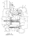
- the illustrated variable geometry turbine comprises a turbine housing 1 defining a volute or inlet chamber 2 to which exhaust gas from an internal combustion engine (not shown) is delivered.
- the exhaust gas flows from the inlet chamber 2 to an outlet passageway 3 via an inlet passageway defined on one side by a movable annular member 4 and on the other side by a wall 5 which faces the movable annular wall member 4.
- An array of nozzle vanes 6 supported on a nozzle support ring 7 extends across the inlet passageway. Gas flowing from the inlet passageway 2 to the outlet passageway 3 passes over a turbine wheel 8 and as a result a torque is applied to a turbocharger shaft 9 which drives a compressor wheel 10. Rotation of the wheel 10 pressurises ambient air present in an air inlet 11 and delivers the pressurised air to an air outlet or volute 12. That pressurised air is fed to the internal combustion engine (not shown).
- the movable annular wall member 4 is contacted by a sealing ring 13 and comprises a radially inner tubular wall 14, a radially extending annular portion 15 which defined slots through which the vanes 6 extend, a radially outer tubular portion 16 which bears against the sealing ring 13, and a radially extending flange 17.
- the radially outer tubular portion 16 is engaged by two diametrically opposed members 18 which are supported on respective guide pins 19.
- the nozzle support 7 is mounted on an array of four guide pins 20 so as to be movable parallel to the axis of rotation of the turbocharger.
- Each of the guide pins 20 is biased by a compression spring 21 towards the right in Figs. 2 to 4.
- the nozzle support 7 and the vanes mounted on it are biased towards the right in Figs. 2 to 4 and accordingly normally assume the position shown in Fig. 2, with the free ends of the vanes 6 bearing against the facing wall 5 of the inlet passageway.
- a pneumatically operated actuator 22 is operable to control the position of an output shaft 23 that is linked to a stirrup member 24 that engages each of the guide pins 19.
- Fig. 2 shows the movable annular wall member in its fully closed position in which the radially extending portion 15 of the member abuts the facing wall 5 of the inlet passageway.
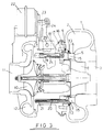
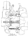
- Fig. 3 shows the annular wall member 4 in a half open position and Fig. 4 shows the annular wall member 4 in a fully open position.
- the actuator 22 is positioned at a considerable distance from the turbine axis, space is not a problem.
- the precise radial position of the actuator shaft 23 is not critical, allowing tolerances to be increased. Equally radial expansion due to thermal distortion is not a critical problem.
- a dotted line 25 indicates an imaginary surface which is coplanar with the end surface of the turbine housing the downstream side of the movable member 4 and adjacent which the turbine wheel 8 is positioned. This surface in effect defines one side of the inlet passageway to the turbine chamber.
- the wall of the inlet passageway defined by the movable annular wall member 4 is aligned with the imaginary surface 25 the spacing between the annular wall member 4 and the facing wall 5 is for the purposes of the present description deemed to correspond to the inlet width of the inlet passageway downstream of the vanes 6. This condition is referred to below as 100% of nominal inlet width.
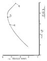
- FIG. 5 this illustrates the effect on turbine efficiency of movements of the annular wall member 4 and the nozzle support 7.
- the point on the curve corresponding to 100% of nominal inlet width is indicated by numeral 26.
- the points on the curve corresponding to 135% opening and 165% opening are indicated by numerals 27 and 28 respectively.
- the ability to extend the characteristic curve to point 28 increases the mean turbine efficiency by avoiding operating the turbine in the less efficient region indicated by the left-hand end of the curve in Fig. 5.
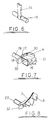
- Fig. 6 this shows the interengagement between the stirrup 24 and one of the guide pins 19 upon which the movable annular wall member 4 is mounted.
- the two ends of the stirrup 24 engage in slots cut in side surfaces of pins 19.
- the edges of the stirrup ends which bear against the ends of the slots are curved so that the clearance between each stirrup end and the slot ends is constant.
- the stirrup 24 is pivoted on pivot pins 29 so that the stirrup 24 forms a lever which can be moved to precisely position the pins 19.
- the stirrup 24 is formed from sheet steel arranged such that the stirrup is relatively stiff in the direction parallel to the axis of pins 19 but relatively flexible perpendicular to the pins.
- Fig. 7 illustrates the interengagement between the guide pins 19 and the annular wall member 4.
- the member 4 is exposed to large variations in temperature and pressure and can accordingly distort to a certain degree. If the linkage between the member 4 and the pin 19 was rigid such distortion would apply significant transverse forces to the pins 19. Accordingly the engagement between the member 4 and 19 is such that distortion of the member 4 can be accommodated without applying transverse forces to the pin.
- the bridge links 18 can be thicker than the flange 17 to maintain a stiff joint in the axial direction, and the width of the links 18 maintains a good resistance to tilting of the member 4 relative to the turbine axis.
- FIG. 8 this illustrates the interrelationship between the spring biased support pins 20 and the nozzle support 7 on which the vanes 6 are mounted.
- Each pin 20 has rigidly mounted on its end a bracket 32 which has a flat surface engaging the rear side of the nozzle support ring 7 and an inner edge which is flanged to engage inside the radially inner edge of the nozzle support ring 7.
- the illustrated arrangement comprises a single annular seal 13 arranged around the radially outer side of the movable wall member 4.
- Alternative sealing arrangements are possible, however, for example a pair of seals arranged respectively on the radially inner and outer portions of the movable annular wall member 4.
Landscapes
- Engineering & Computer Science (AREA)
- Mechanical Engineering (AREA)
- General Engineering & Computer Science (AREA)
- Control Of Turbines (AREA)
- Supercharger (AREA)
Claims (5)
Applications Claiming Priority (2)
| Application Number | Priority Date | Filing Date | Title |
|---|---|---|---|
| GB8811623 | 1988-05-17 | ||
| GB8811623A GB2218744B (en) | 1988-05-17 | 1988-05-17 | Variable geometry turbine |
Publications (2)
| Publication Number | Publication Date |
|---|---|
| EP0342889A1 EP0342889A1 (de) | 1989-11-23 |
| EP0342889B1 true EP0342889B1 (de) | 1992-04-29 |
Family
ID=10637018
Family Applications (1)
| Application Number | Title | Priority Date | Filing Date |
|---|---|---|---|
| EP89304869A Expired EP0342889B1 (de) | 1988-05-17 | 1989-05-15 | Turbine mit variabler Statorgeometrie |
Country Status (8)
| Country | Link |
|---|---|
| US (1) | US4973223A (de) |
| EP (1) | EP0342889B1 (de) |
| JP (1) | JP2730968B2 (de) |
| BR (1) | BR8902302A (de) |
| DE (1) | DE68901360D1 (de) |
| ES (1) | ES2030973T3 (de) |
| GB (1) | GB2218744B (de) |
| MX (1) | MX171870B (de) |
Families Citing this family (24)
| Publication number | Priority date | Publication date | Assignee | Title |
|---|---|---|---|---|
| PT8409T (pt) * | 1991-12-09 | 1993-06-30 | Antonio Manuel Da Costa Lage | Greencar |
| EP0571205B1 (de) * | 1992-05-21 | 1997-03-05 | Alliedsignal Limited | Regelbarer Turbolader |
| GB2326198A (en) | 1997-06-10 | 1998-12-16 | Holset Engineering Co | Variable geometry turbine |
| GB9711893D0 (en) | 1997-06-10 | 1997-08-06 | Holset Engineering Co | Variable geometry turbine |
| US6652224B2 (en) * | 2002-04-08 | 2003-11-25 | Holset Engineering Company Ltd. | Variable geometry turbine |
| US6941755B2 (en) * | 2003-10-28 | 2005-09-13 | Daimlerchrysler Corporation | Integrated bypass and variable geometry configuration for an exhaust gas turbocharger |
| US7581394B2 (en) * | 2003-12-10 | 2009-09-01 | Honeywell International Inc. | Variable nozzle device for a turbocharger |
| US7165936B2 (en) * | 2004-08-16 | 2007-01-23 | Honeywell International, Inc. | Adjustable flow turbine nozzle |
| KR101070903B1 (ko) * | 2004-08-19 | 2011-10-06 | 삼성테크윈 주식회사 | 가변 베인형 터빈 |
| US20070089413A1 (en) * | 2005-10-21 | 2007-04-26 | Edward Green | Turbo catalyst light-off device |
| WO2008045074A1 (en) * | 2006-10-12 | 2008-04-17 | United Technologies Corporation | Turbofan engine with variable bypass nozzle exit area and method of operation |
| JP2008215083A (ja) * | 2007-02-28 | 2008-09-18 | Mitsubishi Heavy Ind Ltd | 可変容量型排気ターボ過給機における可変ノズル機構部取付構造 |
| CN101743379A (zh) * | 2007-04-10 | 2010-06-16 | 艾利奥特公司 | 具有可调进口导向叶片的离心式压缩机 |
| US8608434B2 (en) | 2008-04-01 | 2013-12-17 | Cummins Turbo Technologies Limited | Variable geometry turbine |
| WO2009145276A1 (ja) | 2008-05-28 | 2009-12-03 | 京セラ株式会社 | バンドパスフィルタならびにそれを用いた無線通信モジュールおよび無線通信機器 |
| US8704619B2 (en) | 2008-05-28 | 2014-04-22 | Kyocera Corporation | Bandpass filter and radio communication module and radio communication device using the same |
| DE102009004890A1 (de) * | 2009-01-16 | 2010-07-22 | Bosch Mahle Turbo Systems Gmbh & Co. Kg | Ladeeinrichtung |
| GB2468871B (en) * | 2009-03-25 | 2015-03-18 | Cummins Turbo Tech Ltd | Turbocharger |
| US20110173973A1 (en) * | 2010-01-20 | 2011-07-21 | International Engine Intellectrual Property Company, LLC | Turbine inlet flow modulator |
| US8967956B2 (en) * | 2011-09-26 | 2015-03-03 | Honeywell International Inc. | Turbocharger variable-nozzle assembly with vane sealing arrangement |
| US8967955B2 (en) * | 2011-09-26 | 2015-03-03 | Honeywell International Inc. | Turbocharger with variable nozzle having labyrinth seal for vanes |
| US9932888B2 (en) | 2016-03-24 | 2018-04-03 | Borgwarner Inc. | Variable geometry turbocharger |
| JP7317657B2 (ja) * | 2019-10-07 | 2023-07-31 | トヨタ自動車株式会社 | ターボチャージャ |
| GB2609447B (en) * | 2021-07-30 | 2026-04-22 | Cummins Ltd | Variable geometry turbine |
Family Cites Families (14)
| Publication number | Priority date | Publication date | Assignee | Title |
|---|---|---|---|---|
| US1322810A (en) * | 1919-11-25 | Rotary pump with adjustable gate | ||
| US1656012A (en) * | 1928-01-10 | Hydraulic machine | ||
| US2861774A (en) * | 1950-02-16 | 1958-11-25 | Alfred J Buchi | Inlet control for radial flow turbines |
| GB691144A (en) * | 1950-02-16 | 1953-05-06 | Alfred Buechi | Inlet control device for radial flow turbine wheels |
| US2846185A (en) * | 1955-02-22 | 1958-08-05 | Sfindex | Full admission impulse turbine |
| DE1074206B (de) * | 1958-01-20 | 1960-01-28 | Gebrüder Sulzer Aktiengesellschaft, Winterthur (Schweiz) | Leitrad für Turbomaschinen |
| NL139802B (nl) * | 1968-05-31 | 1973-09-17 | Stork Koninklijke Maschf | Turbine voor een compressibel medium. |
| GB1473248A (en) * | 1975-01-04 | 1977-05-11 | G Sojuz Ni Traktor I | Turbochargers |
| JPS58594B2 (ja) * | 1978-03-31 | 1983-01-07 | 日立造船株式会社 | 遠心圧縮機 |
| US4403914A (en) * | 1981-07-13 | 1983-09-13 | Teledyne Industries, Inc. | Variable geometry device for turbomachinery |
| US4527949A (en) * | 1983-09-12 | 1985-07-09 | Carrier Corporation | Variable width diffuser |
| DE161559T1 (de) * | 1984-05-15 | 1986-04-10 | Aktieselskabet Kongsberg Vaepenfabrikk, Kongsberg | Einstecktiefe- und winkelstandregelungseinrichtung fuer verdichtereinlassleitschaufel. |
| US4643639A (en) * | 1984-12-24 | 1987-02-17 | Sundstrand Corporation | Adjustable centrifugal pump |
| US4802817A (en) * | 1987-12-23 | 1989-02-07 | Sundstrand Corporation | Centrifugal pump with self-regulating impeller discharge shutter |
-
1988
- 1988-05-17 GB GB8811623A patent/GB2218744B/en not_active Expired - Lifetime
-
1989
- 1989-05-15 ES ES198989304869T patent/ES2030973T3/es not_active Expired - Lifetime
- 1989-05-15 DE DE8989304869T patent/DE68901360D1/de not_active Expired - Lifetime
- 1989-05-15 EP EP89304869A patent/EP0342889B1/de not_active Expired
- 1989-05-15 US US07/352,095 patent/US4973223A/en not_active Expired - Lifetime
- 1989-05-17 BR BR898902302A patent/BR8902302A/pt not_active IP Right Cessation
- 1989-05-17 MX MX016080A patent/MX171870B/es unknown
- 1989-05-17 JP JP1121635A patent/JP2730968B2/ja not_active Expired - Lifetime
Also Published As
| Publication number | Publication date |
|---|---|
| GB8811623D0 (en) | 1988-06-22 |
| JPH0264203A (ja) | 1990-03-05 |
| GB2218744B (en) | 1992-03-18 |
| EP0342889A1 (de) | 1989-11-23 |
| ES2030973T3 (es) | 1992-11-16 |
| JP2730968B2 (ja) | 1998-03-25 |
| DE68901360D1 (de) | 1992-06-04 |
| US4973223A (en) | 1990-11-27 |
| BR8902302A (pt) | 1990-01-09 |
| GB2218744A (en) | 1989-11-22 |
| MX171870B (es) | 1993-11-22 |
Similar Documents
| Publication | Publication Date | Title |
|---|---|---|
| EP0342889B1 (de) | Turbine mit variabler Statorgeometrie | |
| EP0342890B1 (de) | Betätigungseinrichtung für den Verstell-Leitapparat einer Turbine | |
| EP0342888B1 (de) | Montage einer verschiebbaren Wand im Einlass einer Radialturbine | |
| EP0654587B1 (de) | Turbine mit variabler Einlassgeometrie | |
| US8172516B2 (en) | Variable geometry turbine | |
| US6543992B2 (en) | Control arrangement | |
| KR100398007B1 (ko) | 가스터빈엔진 | |
| CA1162748A (en) | Integrated multiplane actuator system for compressor variable vanes and air bleed valve | |
| JPH0713468B2 (ja) | タ−ボチヤ−ジヤ | |
| EP3140518B1 (de) | Turbinenanordnung mit variabler geometrie | |
| EP1595060B1 (de) | Leitschaufel-vorrichtung eines turboladers und steuerungsverfahren dafür | |
| EP3794220B1 (de) | Schaufeln und ummantelung für eine turbomaschine | |
| CA1143706A (en) | Variable vane seal | |
| US5183381A (en) | Variable geometry turbine inlet wall mounting assembly | |
| US8356973B2 (en) | Turbocharger | |
| US11441435B2 (en) | Vane arrangement for a turbo-machine | |
| US20020146316A1 (en) | Methods and apparatus for adjusting gas turbine engine variable vanes | |
| US20220251960A1 (en) | Vanes and shrouds for a turbo-machine | |
| EP3530881B1 (de) | Turbine mit variabler geometrie |
Legal Events
| Date | Code | Title | Description |
|---|---|---|---|
| PUAI | Public reference made under article 153(3) epc to a published international application that has entered the european phase |
Free format text: ORIGINAL CODE: 0009012 |
|
| AK | Designated contracting states |
Kind code of ref document: A1 Designated state(s): DE ES FR GB IT SE |
|
| 17P | Request for examination filed |
Effective date: 19900508 |
|
| 17Q | First examination report despatched |
Effective date: 19910621 |
|
| GRAA | (expected) grant |
Free format text: ORIGINAL CODE: 0009210 |
|
| AK | Designated contracting states |
Kind code of ref document: B1 Designated state(s): DE ES FR GB IT SE |
|
| REF | Corresponds to: |
Ref document number: 68901360 Country of ref document: DE Date of ref document: 19920604 |
|
| ET | Fr: translation filed | ||
| ITF | It: translation for a ep patent filed | ||
| REG | Reference to a national code |
Ref country code: ES Ref legal event code: FG2A Ref document number: 2030973 Country of ref document: ES Kind code of ref document: T3 |
|
| PLBE | No opposition filed within time limit |
Free format text: ORIGINAL CODE: 0009261 |
|
| STAA | Information on the status of an ep patent application or granted ep patent |
Free format text: STATUS: NO OPPOSITION FILED WITHIN TIME LIMIT |
|
| 26N | No opposition filed | ||
| EAL | Se: european patent in force in sweden |
Ref document number: 89304869.4 |
|
| PGFP | Annual fee paid to national office [announced via postgrant information from national office to epo] |
Ref country code: SE Payment date: 19980515 Year of fee payment: 10 |
|
| PGFP | Annual fee paid to national office [announced via postgrant information from national office to epo] |
Ref country code: ES Payment date: 19980526 Year of fee payment: 10 |
|
| PG25 | Lapsed in a contracting state [announced via postgrant information from national office to epo] |
Ref country code: SE Free format text: LAPSE BECAUSE OF NON-PAYMENT OF DUE FEES Effective date: 19990516 |
|
| PG25 | Lapsed in a contracting state [announced via postgrant information from national office to epo] |
Ref country code: ES Free format text: LAPSE BECAUSE OF EXPIRATION OF PROTECTION Effective date: 19990517 |
|
| EUG | Se: european patent has lapsed |
Ref document number: 89304869.4 |
|
| REG | Reference to a national code |
Ref country code: ES Ref legal event code: FD2A Effective date: 20010601 |
|
| REG | Reference to a national code |
Ref country code: GB Ref legal event code: IF02 |
|
| PGFP | Annual fee paid to national office [announced via postgrant information from national office to epo] |
Ref country code: GB Payment date: 20050511 Year of fee payment: 17 Ref country code: FR Payment date: 20050511 Year of fee payment: 17 |
|
| PGFP | Annual fee paid to national office [announced via postgrant information from national office to epo] |
Ref country code: DE Payment date: 20050512 Year of fee payment: 17 |
|
| PG25 | Lapsed in a contracting state [announced via postgrant information from national office to epo] |
Ref country code: IT Free format text: LAPSE BECAUSE OF NON-PAYMENT OF DUE FEES;WARNING: LAPSES OF ITALIAN PATENTS WITH EFFECTIVE DATE BEFORE 2007 MAY HAVE OCCURRED AT ANY TIME BEFORE 2007. THE CORRECT EFFECTIVE DATE MAY BE DIFFERENT FROM THE ONE RECORDED. Effective date: 20050515 |
|
| PG25 | Lapsed in a contracting state [announced via postgrant information from national office to epo] |
Ref country code: GB Free format text: LAPSE BECAUSE OF NON-PAYMENT OF DUE FEES Effective date: 20060515 |
|
| PG25 | Lapsed in a contracting state [announced via postgrant information from national office to epo] |
Ref country code: DE Free format text: LAPSE BECAUSE OF NON-PAYMENT OF DUE FEES Effective date: 20061201 |
|
| GBPC | Gb: european patent ceased through non-payment of renewal fee |
Effective date: 20060515 |
|
| REG | Reference to a national code |
Ref country code: FR Ref legal event code: ST Effective date: 20070131 |
|
| PG25 | Lapsed in a contracting state [announced via postgrant information from national office to epo] |
Ref country code: FR Free format text: LAPSE BECAUSE OF NON-PAYMENT OF DUE FEES Effective date: 20060531 |