EP0342874B1 - Ultraschallwandler für eine medizinische Abbildungsanordnung - Google Patents
Ultraschallwandler für eine medizinische Abbildungsanordnung Download PDFInfo
- Publication number
- EP0342874B1 EP0342874B1 EP89304827A EP89304827A EP0342874B1 EP 0342874 B1 EP0342874 B1 EP 0342874B1 EP 89304827 A EP89304827 A EP 89304827A EP 89304827 A EP89304827 A EP 89304827A EP 0342874 B1 EP0342874 B1 EP 0342874B1
- Authority
- EP
- European Patent Office
- Prior art keywords
- ultrasound
- ultrasound probe
- piezoelectric vibrator
- depth
- absorber
- Prior art date
- Legal status (The legal status is an assumption and is not a legal conclusion. Google has not performed a legal analysis and makes no representation as to the accuracy of the status listed.)
- Expired - Lifetime
Links
Images


Classifications
-
- B—PERFORMING OPERATIONS; TRANSPORTING
- B06—GENERATING OR TRANSMITTING MECHANICAL VIBRATIONS IN GENERAL
- B06B—METHODS OR APPARATUS FOR GENERATING OR TRANSMITTING MECHANICAL VIBRATIONS OF INFRASONIC, SONIC, OR ULTRASONIC FREQUENCY, e.g. FOR PERFORMING MECHANICAL WORK IN GENERAL
- B06B1/00—Methods or apparatus for generating mechanical vibrations of infrasonic, sonic, or ultrasonic frequency
- B06B1/02—Methods or apparatus for generating mechanical vibrations of infrasonic, sonic, or ultrasonic frequency making use of electrical energy
- B06B1/06—Methods or apparatus for generating mechanical vibrations of infrasonic, sonic, or ultrasonic frequency making use of electrical energy operating with piezoelectric effect or with electrostriction
- B06B1/0607—Methods or apparatus for generating mechanical vibrations of infrasonic, sonic, or ultrasonic frequency making use of electrical energy operating with piezoelectric effect or with electrostriction using multiple elements
- B06B1/0622—Methods or apparatus for generating mechanical vibrations of infrasonic, sonic, or ultrasonic frequency making use of electrical energy operating with piezoelectric effect or with electrostriction using multiple elements on one surface
Definitions
- the present invention relates to an ultrasound probe for a medical imaging system, more particularly, to an array type ultrasound probe.
- An ultrasound probe which is used as an analog front end for a medical imaging system, provides a large number of independent channels, transduces electric signals to acoustic pressure, and generates sufficient acoustic energy to examine the various structures in the human body. Further, the ultrasound probe converts the weak returning acoustic echoes to a set of electrical signals which can be processed into an image.
- an ultrasound probe for a medical imaging system comprises an ultrasound absorber and a piezoelectric vibrator mounted on the ultrasound absorber, and is cut from the surface of the piezoelectric vibrator to the ultrasound absorber into the form of an array by a plurality of cutting grooves.
- Such an ultrasound probe is disclosed in Japanese Unexamined Patent Publication (Kokai) No. 58-118739.
- An embodiment of the present invention may provide an ultrasound probe for a medical imaging system having preferable frequency characteristics by setting a depth d of each cutting groove in an ultrasound absorber to a specific value.
- the coefficient n may be an even number or an odd number.
- the existing ultrasound probe comprises an ultrasound absorber 103, a piezoelectric vibrator 101, a first and a second electrodes 102a and 102b, and an acoustic matching layer 104.
- the ultrasound absorber 103 is used for absorbing unnecessary (unwanted) ultrasound waves radiated from the piezoelectric vibrator 101.
- the piezoelectric vibrator 101 is mounted on the ultrasound absorber 103 through the first electrode 102a, and the acoustic matching layer 104 is mounted on the piezoelectric vibrator 101 through the second electrode 102b. Namely, the piezoelectric vibrator 101 is positioned between the first electrode 102a and the second electrode 102b and driven by the first and second electrodes 102a and 102b.
- the acoustic matching layer 104 is used for acoustic impedance matching between the human body and the piezoelectric vibrator 101.
- 105 is a lead.
- the ultrasound probe is cut from the surface of the acoustic matching layer 104 toward the ultrasound absorber 103 in the form of an array by a plurality of cutting grooves 106.
- a cutting depth of each cutting groove 106 is not considered or a relationship between the cutting depth and a gain has not been studied sufficiently, and thus the depths of the cutting grooves 106 are scattered.
- the ultrasound absorber 103 is deeply cut by the cutting grooves 106 out of necessity, and in other cases, the ultrasound absorber 103 is shallowly cut or is not cut at all by the cutting grooves 106, and the depth of the cutting grooves 106 in the ultrasound absorber 103 is not defined to be a specific value. Consequently, symmetrical electro-acoustic conversion characteristics of the existing ultrasound probe cannot be satisfied in the frequency domain.
- the ultrasound diagnostic apparatus is, for example, used for diagnosing a human body by using an ultrasound wave. Namely, the ultrasound diagnostic apparatus diagnoses internal organs or tumors of the human body by their shapes or acoustic characteristics thereof. Note, recently, the acoustic characteristics of tissues in the internal organs or tumors are, for example, characterized by an attenuation coefficient and a scattered coefficient. When the attenuation coefficient and the scattered coefficient are used in the ultrasound diagnostic apparatus, a pervasive disease or, e.g. cancer of a liver can be detected, furthermore, a myocardial infarction can be detected by the ultrasound diagnostic apparatus.
- FIG. 2 is a block diagram showing an example of an ultrasound diagnostic apparatus using an ultrasound probe for a medical imaging system according to the present invention.
- reference numerals 10 denotes an ultrasound probe
- 11 denotes a transmitting amplifier
- 12 denotes a receiving amplifier
- 19 denotes a display
- references BS denotes a body surface and ROI denotes a region of interest.
- the ultrasound probe 10 is used for radiating an ultrasound beam to a region of interest ROI in a human body through the body surface BS, and receiving an ultrasound wave reflected by the region of interest ROI.
- the transmitting amplifier (which is an ultrasound pulser) 11 supplied with signals from a timing control portion 16, is used for driving the ultrasound probe 10 by inputting pulse signals to the ultrasound probe 10.
- the receiving amplifier 12 is used for amplifying the ultrasound wave signals received by the ultrasound probe 10.
- An output signal of the receiving amplifier 12 is supplied to a B-mode receiving circuit 13, a scattered spectrum calculation portion 14, and a scattered power calculation portion 15, respectively.
- the region of interest ROI is, for example, a part of internal organs, tumors, etc., which are suspected of a disease.
- the B-mode receiving circuit 13 generates a B-mode image by luminance signals corresponding to a signal strength of the reflected ultrasound wave signals output from the receiving amplifier 12. An output signal of the B-mode receiving circuit 13 is supplied to the display 19.
- the scattered spectrum calculation portion 14 is used for calculating a scattered spectrum based on the ultrasound wave signals output from the receiving amplifier 12.
- the scattered power calculation portion 15 is used for calculating a scattered ultrasound wave power based on the ultrasound wave signals output from the receiving amplifier 12.
- the timing control portion 16 controls timings of various signals, and output signals of the timing control portion 26 are supplied to the scattered power calculation portion 15 and a ROM 17.
- the ROM 17 is a read only memory for storing various data in response to addresses.
- the stored data of the ROM 17 are, for example, scattered characteristics of the ultrasound beam, transmit and receive characteristics, and power transfer functions including frequency characteristics of the ultrasound diagnostic apparatus.
- Output signals of the scattered spectrum calculation portion 14, the scattered power calculation portion 15, and the ROM 17 are supplied to a coefficient calculation portion 18.
- the coefficient calculation portion 18 is used for calculating an attenuation coefficient, a scattered coefficient, etc., and an output of the coefficient calculation portion 18 is supplied to the display 19. Consequently, the display 19 is able to indicate both a B-mode picture image and a picture image characterized by the scattered coefficient and the attenuation coefficient.
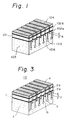
- FIG. 3 is a perspective view showing an embodiment of an ultrasound probe for a medical imaging system according to the present invention
- Fig. 4 is a partly diagrammatic sectional view showing an example of the ultrasound probe shown in Fig. 3.
- reference numeral 1 denotes a piezoelectric vibrator
- 2a and 2b denote electrodes
- 3 denotes an ultrasound absorber
- 4 denotes an acoustic matching layer
- 5 denotes a lead
- 6 denotes cutting grooves
- references d denotes a depth of the cutting groove in the ultrasound absorber
- Z denotes an acoustic impedance of the ultrasound absorber 4
- Z ' denotes an acoustic impedance of a cut portion in the ultrasound absorber 4.
- This configuration of the ultrasound probe of the present embodiment is same as the existing-type probe of Fig. 1.
- an acoustic velocity of a cut portion 7 of the ultrasound absorber 3 is lower than that of a non-cut portion thereof.
- an acoustic impedance Z' of the cut portion 7 is smaller than an acoustic impedance Z of the non-cut portion in the ultrasound absorber 3.
- This configuration is equivalent to a new layer of a depth d having an acoustic impedance Z', which is smaller than an acoustic impedance Z, being mounted to a rear of the piezoelectric vibrator 1.
- an ultrasound probe effectively includes a new acoustic matching layer located to the rear of the piezoelectric vibrator 1, and the new acoustic matching layer has a depth of d and an impedance of Z'.
- the depth d of the new rear acoustic matching layer is changed, frequency characteristics of the ultrasound probe are changed as shown in Figs. 5 to 8.
- Figure 5 is a diagram showing an example of gain-frequency characteristics of an ultrasound probe.
- a gain against a frequency in the case of the depth d of each of the cutting grooves 6 is determined to ranges of ⁇ /4 to ⁇ /2 (which is indicated by a solid line), and ⁇ /2 to 3 ⁇ /4 (which is indicated by a dot line) are shown.
- ⁇ /4 to ⁇ /2 which is indicated by a solid line
- ⁇ /2 to 3 ⁇ /4 which is indicated by a dot line
- the gain-frequency characteristics of the ultrasound probe are not symmetrical in relation to a center frequency f0 of ultrasound waves which are radiated from the piezoelectric vibrator 1 and corresponds to the wave length ⁇ .
- FIG. 6 is a diagram showing an example of gain-frequency characteristics of an ultrasound probe applicable to the present invention.
- a gain against a frequency in the case of the depth d of each of the cutting grooves 6 is determined to 0, ⁇ /4 and ⁇ /2.
- the gain-frequency characteristics of the ultrasound probe are symmetrical in regard to a center frequency f0 of ultrasound waves which are radiated from the piezoelectric vibrator 1 and correspond to the wave length ⁇ .
- n 0 implies no grooves are present, and is outside the scope of the present invention.
- a depth d of each of the cutting grooves 6 equals 1/4 ⁇
- a height of the gain G reaches a highest value
- a depth d of each of the cutting grooves 6 equals 1/2 ⁇
- a band width of the gain G reaches a broadest value.
- Figure 7 is a diagram showing an example of a relationship between a gain (an ultrasound radiation gain of a center frequency f0) G and a depth d of a groove 6 in an ultrasound probe.
- Figure 8 is a diagram showing an example of a relationship between a relative band width ( ⁇ f/f0) BW and a depth d of a groove 6 in an ultrasound probe.
- the relative band is a value that a band width ⁇ f at positions lower by -6dB than an gain G of the center frequency f0 divided by the center frequency f0, when a depth d of each of the cutting grooves 6 is changed to various values.
- the relative band width BW reaches a highest value.
- Electrodes 2a and 2b are mounted on to both sides of the piezoelectric vibrator 1.
- an acoustic matching layer 4 is mounted on to a front of the piezoelectric vibrator 1
- an ultrasound absorber 3 is mounted on to a rear of the piezoelectric vibrator 1.
- the ultrasound probe is cut from the acoustic matching layer 4 to the ultrasound absorber 3 through the piezoelectric vibrator 1 and the electrodes 2a and 2b by a plurality of cutting grooves 6.
- Figure 9 is a partly diagrammatic sectional view showing a modification of the ultrasound probe shown in Fig. 4.
- the cutting grooves 6 of the embodiment shown in Fig. 4 are formed only by a wide cutting portion, however, the cutting grooves 6a of the modification shown in Fig. 9 are formed by a wide cutting portion 61 and a narrow cutting portion 62.
- Such cutting grooves 6a of the modification of the ultrasound probe can have the same coefficients as the cutting grooves 6 in the embodiment shown in Fig. 4.
- a depth d of a cutting groove 6 in an ultrasound absorber 3 is determined by a positive integer times a 1/4 wave length ⁇ corresponding to a center frequency f0 of an ultrasound wave generated by the piezoelectric vibrator 1, and an array type ultrasound probe having preferable and stable ultrasound frequency characteristics, for example, a symmetrical configuration, a high efficiency and a broad relative band, can be provided.
Landscapes
- Engineering & Computer Science (AREA)
- Mechanical Engineering (AREA)
- Transducers For Ultrasonic Waves (AREA)
- Ultra Sonic Daignosis Equipment (AREA)
- Investigating Or Analyzing Materials By The Use Of Ultrasonic Waves (AREA)
Claims (4)
- Ultraschallsonde für ein medizinisches Abbildungssystem, mit einem Ultraschallabsorber (3), einer ersten Elektrode (2a), die am Ultraschallabsorber (3) montiert ist, einem piezoelektrischen Vibrator (1), der an der genannten ersten Elektrode (2a) montiert ist, und einer zweiten Elektrode (2b), die am genannten piezoelektrischen Vibrator (1) montiert ist, wobei die genannte Ultraschallsonde durch eine Vielzahl von Schnittrillen (6), die von der Außenfläche der genannten zweiten Elektrode (2b) durch den genannten piezoelektrischen Vibrator (1) und die genannte erste Elektrode (2a) zum genannten Ultraschallabsorber (3) verlaufen, in Form eines Arrays eingeschnitten ist;
dadurch gekennzeichnet, daß die Schnittiefe d jeder Rille (6) bestimmt wird durch

worin λ eine Wellenlänge ist, die einer Mittenfrequenz f₀ von Ultraschallwellen, die vom genannten piezoelektrischen Vibrator (1) ausgesendet werden, entspricht, und n eine positive ganze Zahl ist. - Ultraschallsonde nach Anspruch 1, bei welcher n eine gerade Zahl ist.
- Ultraschallsonde nach Anspruch 1, bei welcher n eine ungerade Zahl ist.
- Ultraschallsonde nach Anspruch 1, 2 oder 3, welche ferner eine akustischen Anpaßschicht (4), die an der genannten Außenfläche der genannten zweiten Elektrode (2b) montiert ist, zum Anpassen der Ultraschallwelle umfaßt, und bei welcher die genannten Rillen (6) weiter durch die gesamte Dicke der genannten akustischen Anpaßschicht (4) verlaufen.
Applications Claiming Priority (2)
| Application Number | Priority Date | Filing Date | Title |
|---|---|---|---|
| JP63122438A JP2615132B2 (ja) | 1988-05-19 | 1988-05-19 | 超音波探触子 |
| JP122438/88 | 1988-05-19 |
Publications (3)
| Publication Number | Publication Date |
|---|---|
| EP0342874A2 EP0342874A2 (de) | 1989-11-23 |
| EP0342874A3 EP0342874A3 (de) | 1991-08-07 |
| EP0342874B1 true EP0342874B1 (de) | 1994-09-07 |
Family
ID=14835851
Family Applications (1)
| Application Number | Title | Priority Date | Filing Date |
|---|---|---|---|
| EP89304827A Expired - Lifetime EP0342874B1 (de) | 1988-05-19 | 1989-05-12 | Ultraschallwandler für eine medizinische Abbildungsanordnung |
Country Status (5)
| Country | Link |
|---|---|
| US (1) | US4992989A (de) |
| EP (1) | EP0342874B1 (de) |
| JP (1) | JP2615132B2 (de) |
| AU (1) | AU604408B2 (de) |
| DE (1) | DE68917985T2 (de) |
Cited By (1)
| Publication number | Priority date | Publication date | Assignee | Title |
|---|---|---|---|---|
| DE29708338U1 (de) * | 1997-05-12 | 1998-09-17 | DWL Elektronische Systeme GmbH, 78354 Sipplingen | Multifrequenz-Ultraschallsonde |
Families Citing this family (58)
| Publication number | Priority date | Publication date | Assignee | Title |
|---|---|---|---|---|
| US5005054A (en) * | 1990-07-02 | 1991-04-02 | Xerox Corporation | Frequency sweeping excitation of high frequency vibratory energy producing devices for electrophotographic imaging |
| US5010369A (en) * | 1990-07-02 | 1991-04-23 | Xerox Corporation | Segmented resonator structure having a uniform response for electrophotographic imaging |
| US5025291A (en) * | 1990-07-02 | 1991-06-18 | Zerox Corporation | Edge effect compensation in high frequency vibratory energy producing devices for electrophotographic imaging |
| US5611343A (en) * | 1995-04-05 | 1997-03-18 | Loral Aerospace Corp. | High resolution three-dimensional ultrasound imaging |
| US5655538A (en) * | 1995-06-19 | 1997-08-12 | General Electric Company | Ultrasonic phased array transducer with an ultralow impedance backfill and a method for making |
| US6623430B1 (en) | 1997-10-14 | 2003-09-23 | Guided Therapy Systems, Inc. | Method and apparatus for safety delivering medicants to a region of tissue using imaging, therapy and temperature monitoring ultrasonic system |
| US6050943A (en) | 1997-10-14 | 2000-04-18 | Guided Therapy Systems, Inc. | Imaging, therapy, and temperature monitoring ultrasonic system |
| US7914453B2 (en) | 2000-12-28 | 2011-03-29 | Ardent Sound, Inc. | Visual imaging system for ultrasonic probe |
| CN100399596C (zh) * | 2003-03-12 | 2008-07-02 | 中国科学院声学研究所 | 用于扫描成像装置的相控阵探头 |
| US7393325B2 (en) | 2004-09-16 | 2008-07-01 | Guided Therapy Systems, L.L.C. | Method and system for ultrasound treatment with a multi-directional transducer |
| US9011336B2 (en) | 2004-09-16 | 2015-04-21 | Guided Therapy Systems, Llc | Method and system for combined energy therapy profile |
| US7824348B2 (en) | 2004-09-16 | 2010-11-02 | Guided Therapy Systems, L.L.C. | System and method for variable depth ultrasound treatment |
| US8535228B2 (en) | 2004-10-06 | 2013-09-17 | Guided Therapy Systems, Llc | Method and system for noninvasive face lifts and deep tissue tightening |
| US8444562B2 (en) | 2004-10-06 | 2013-05-21 | Guided Therapy Systems, Llc | System and method for treating muscle, tendon, ligament and cartilage tissue |
| US10864385B2 (en) | 2004-09-24 | 2020-12-15 | Guided Therapy Systems, Llc | Rejuvenating skin by heating tissue for cosmetic treatment of the face and body |
| US7530958B2 (en) * | 2004-09-24 | 2009-05-12 | Guided Therapy Systems, Inc. | Method and system for combined ultrasound treatment |
| PT2409728T (pt) | 2004-10-06 | 2017-11-16 | Guided Therapy Systems Llc | Sistema para o tratamento de tecidos por ultrassons |
| US8133180B2 (en) | 2004-10-06 | 2012-03-13 | Guided Therapy Systems, L.L.C. | Method and system for treating cellulite |
| US20060111744A1 (en) | 2004-10-13 | 2006-05-25 | Guided Therapy Systems, L.L.C. | Method and system for treatment of sweat glands |
| US8690778B2 (en) | 2004-10-06 | 2014-04-08 | Guided Therapy Systems, Llc | Energy-based tissue tightening |
| EP2279697A3 (de) | 2004-10-06 | 2014-02-19 | Guided Therapy Systems, L.L.C. | Verfahren und System zur nicht invasiven kosmetischen Verbesserung von Blutgefäßerkrankungen |
| US7758524B2 (en) | 2004-10-06 | 2010-07-20 | Guided Therapy Systems, L.L.C. | Method and system for ultra-high frequency ultrasound treatment |
| US9827449B2 (en) | 2004-10-06 | 2017-11-28 | Guided Therapy Systems, L.L.C. | Systems for treating skin laxity |
| US11883688B2 (en) | 2004-10-06 | 2024-01-30 | Guided Therapy Systems, Llc | Energy based fat reduction |
| US11235179B2 (en) | 2004-10-06 | 2022-02-01 | Guided Therapy Systems, Llc | Energy based skin gland treatment |
| US9694212B2 (en) | 2004-10-06 | 2017-07-04 | Guided Therapy Systems, Llc | Method and system for ultrasound treatment of skin |
| US11724133B2 (en) | 2004-10-07 | 2023-08-15 | Guided Therapy Systems, Llc | Ultrasound probe for treatment of skin |
| US11207548B2 (en) | 2004-10-07 | 2021-12-28 | Guided Therapy Systems, L.L.C. | Ultrasound probe for treating skin laxity |
| EP2533130A1 (de) | 2005-04-25 | 2012-12-12 | Ardent Sound, Inc. | Verfahren und System zur Verbesserung der peripheren Computersicherheit |
| RU2294061C1 (ru) * | 2005-06-14 | 2007-02-20 | Государственное образовательное учреждение высшего профессионального образования "Ростовский Государственный Университет" (РГУ) | Многоэлементный пьезоэлектрический преобразователь и способ его изготовления |
| US9566454B2 (en) * | 2006-09-18 | 2017-02-14 | Guided Therapy Systems, Llc | Method and sysem for non-ablative acne treatment and prevention |
| US20150174388A1 (en) | 2007-05-07 | 2015-06-25 | Guided Therapy Systems, Llc | Methods and Systems for Ultrasound Assisted Delivery of a Medicant to Tissue |
| TWI526233B (zh) | 2007-05-07 | 2016-03-21 | 指導治療系統股份有限公司 | 利用聲波能量調製藥劑輸送及效能之系統 |
| JP5358078B2 (ja) * | 2007-10-01 | 2013-12-04 | 日立アロカメディカル株式会社 | 超音波探触子 |
| JP2009082612A (ja) * | 2007-10-02 | 2009-04-23 | Toshiba Corp | 超音波探触子及び圧電振動子 |
| PT3058875T (pt) | 2008-06-06 | 2022-09-20 | Ulthera Inc | Sistema para tratamento cosmético e imagiologia |
| US12102473B2 (en) | 2008-06-06 | 2024-10-01 | Ulthera, Inc. | Systems for ultrasound treatment |
| JP2012513837A (ja) | 2008-12-24 | 2012-06-21 | ガイデッド セラピー システムズ, エルエルシー | 脂肪減少および/またはセルライト処置のための方法およびシステム |
| US8715186B2 (en) | 2009-11-24 | 2014-05-06 | Guided Therapy Systems, Llc | Methods and systems for generating thermal bubbles for improved ultrasound imaging and therapy |
| US9504446B2 (en) | 2010-08-02 | 2016-11-29 | Guided Therapy Systems, Llc | Systems and methods for coupling an ultrasound source to tissue |
| WO2012018391A2 (en) | 2010-08-02 | 2012-02-09 | Guided Therapy Systems, Llc | Methods and systems for treating plantar fascia |
| US8857438B2 (en) | 2010-11-08 | 2014-10-14 | Ulthera, Inc. | Devices and methods for acoustic shielding |
| JP5725978B2 (ja) * | 2011-06-02 | 2015-05-27 | 株式会社東芝 | 超音波プローブ |
| KR102068724B1 (ko) | 2011-07-10 | 2020-01-21 | 가이디드 테라피 시스템스, 엘.엘.씨. | 에너지원으로 초음파를 이용한 피부 외양을 개선하는 시스템 및 방법 |
| WO2013012641A1 (en) | 2011-07-11 | 2013-01-24 | Guided Therapy Systems, Llc | Systems and methods for coupling an ultrasound source to tissue |
| US9263663B2 (en) | 2012-04-13 | 2016-02-16 | Ardent Sound, Inc. | Method of making thick film transducer arrays |
| US9510802B2 (en) | 2012-09-21 | 2016-12-06 | Guided Therapy Systems, Llc | Reflective ultrasound technology for dermatological treatments |
| CN204637350U (zh) | 2013-03-08 | 2015-09-16 | 奥赛拉公司 | 美学成像与处理系统、多焦点处理系统和执行美容过程的系统 |
| WO2014146022A2 (en) | 2013-03-15 | 2014-09-18 | Guided Therapy Systems Llc | Ultrasound treatment device and methods of use |
| BR112016023889B1 (pt) | 2014-04-18 | 2023-02-07 | Ulthera, Inc | Sistema de transdução de ultrassom para ultrassom de focagem linear |
| SG11201804701QA (en) | 2016-01-18 | 2018-07-30 | Ulthera Inc | Compact ultrasound device having annular ultrasound array peripherally electrically connected to flexible printed circuit board and method of assembly thereof |
| DK3981466T3 (da) | 2016-08-16 | 2023-10-09 | Ulthera Inc | Systemer og fremgangsmåder til kosmetisk ultralydsbehandling af hud |
| TW202529848A (zh) | 2018-01-26 | 2025-08-01 | 美商奧賽拉公司 | 用於多個維度中的同時多聚焦超音治療的系統和方法 |
| US11944849B2 (en) | 2018-02-20 | 2024-04-02 | Ulthera, Inc. | Systems and methods for combined cosmetic treatment of cellulite with ultrasound |
| WO2020112688A1 (en) | 2018-11-30 | 2020-06-04 | Ulthera, Inc. | Systems and methods for enhancing efficacy of ultrasound treatment |
| US12377293B2 (en) | 2019-07-15 | 2025-08-05 | Ulthera, Inc. | Systems and methods for measuring elasticity with imaging of ultrasound multi-focus shearwaves in multiple dimensions |
| CN112353419B (zh) * | 2020-11-30 | 2024-03-15 | 中国科学院苏州生物医学工程技术研究所 | 多阵元扫描式超声波探头及超声成像系统和超声成像方法 |
| GB202019016D0 (en) * | 2020-12-02 | 2021-01-13 | Ionix Advanced Tech Ltd | Transducer and method of manufacture |
Family Cites Families (7)
| Publication number | Priority date | Publication date | Assignee | Title |
|---|---|---|---|---|
| EP0019267B1 (de) * | 1979-05-16 | 1984-08-22 | Toray Industries, Inc. | Piezoelektrischer Schwingungswandler |
| JPS56161799A (en) * | 1980-05-15 | 1981-12-12 | Matsushita Electric Ind Co Ltd | Ultrasonic wave probe |
| JPS58118739A (ja) * | 1982-01-05 | 1983-07-14 | テルモ株式会社 | 超音波探触子およびその製造方法 |
| JPS58195552A (ja) * | 1982-05-10 | 1983-11-14 | 松下電器産業株式会社 | 超音波探触子 |
| JPS5999900A (ja) * | 1982-11-29 | 1984-06-08 | Toshiba Corp | 超音波探触子 |
| JPS60196688A (ja) * | 1984-03-19 | 1985-10-05 | Hitachi Medical Corp | 走査形超音波装置 |
| US4671293A (en) * | 1985-10-15 | 1987-06-09 | North American Philips Corporation | Biplane phased array for ultrasonic medical imaging |
-
1988
- 1988-05-19 JP JP63122438A patent/JP2615132B2/ja not_active Expired - Fee Related
-
1989
- 1989-05-02 US US07/346,527 patent/US4992989A/en not_active Expired - Lifetime
- 1989-05-05 AU AU34092/89A patent/AU604408B2/en not_active Ceased
- 1989-05-12 DE DE68917985T patent/DE68917985T2/de not_active Expired - Fee Related
- 1989-05-12 EP EP89304827A patent/EP0342874B1/de not_active Expired - Lifetime
Cited By (1)
| Publication number | Priority date | Publication date | Assignee | Title |
|---|---|---|---|---|
| DE29708338U1 (de) * | 1997-05-12 | 1998-09-17 | DWL Elektronische Systeme GmbH, 78354 Sipplingen | Multifrequenz-Ultraschallsonde |
Also Published As
| Publication number | Publication date |
|---|---|
| AU604408B2 (en) | 1990-12-13 |
| JP2615132B2 (ja) | 1997-05-28 |
| DE68917985T2 (de) | 1995-02-09 |
| EP0342874A2 (de) | 1989-11-23 |
| JPH01291840A (ja) | 1989-11-24 |
| DE68917985D1 (de) | 1994-10-13 |
| EP0342874A3 (de) | 1991-08-07 |
| AU3409289A (en) | 1989-11-23 |
| US4992989A (en) | 1991-02-12 |
Similar Documents
| Publication | Publication Date | Title |
|---|---|---|
| EP0342874B1 (de) | Ultraschallwandler für eine medizinische Abbildungsanordnung | |
| US4507582A (en) | Matching region for damped piezoelectric ultrasonic apparatus | |
| EP0404154B1 (de) | Ultraschallprobe mit einer bedeckenden Schicht von Stoff mit unregelmässiger Dichte | |
| US6540677B1 (en) | Ultrasound transceiver system for remote operation through a minimal number of connecting wires | |
| CA1130439A (en) | Ultrasonic transducer array | |
| US5678554A (en) | Ultrasound transducer for multiple focusing and method for manufacture thereof | |
| US4241611A (en) | Ultrasonic diagnostic transducer assembly and system | |
| JP4242472B2 (ja) | 超音波トランスデューサ・アレイ及び超音波イメージング・システム | |
| US20030055337A1 (en) | Dual-frequency ultrasonic array transducer and method of harmonic imaging | |
| US4870972A (en) | Multiple-frequency acoustic transducer, especially for medical imaging | |
| KR100353131B1 (ko) | 어포다이즈된수직포커스를갖는초음파트랜스듀서어레이 | |
| US5296777A (en) | Ultrasonic probe | |
| GB2079456A (en) | Extended focus transducer system | |
| GB2117905A (en) | Ultrasonic imaging apparatus | |
| EP0110378B2 (de) | Ultraschallfühler | |
| DE3382720T2 (de) | Elektroakustischer Wandler und eine Sonde oder ein diagnostisches Ultraschallgerät mit einem solchen Wandler. | |
| JPS58135977A (ja) | コリメ−タを有する超音波リニアアレ−変換器 | |
| Ylitalo | On the signal-to-noise ratio of a synthetic aperture ultrasound imaging method | |
| US6312386B1 (en) | Medical ultrasound imaging system with composite delay profile | |
| EP1815795B1 (de) | Ultraschallgerät | |
| JPS649012B2 (de) | ||
| JP3468678B2 (ja) | 超音波探触子 | |
| JPH0226189B2 (de) | ||
| Frizzell et al. | Ultrasound phased arrays for hyperthermia treatment | |
| JP3644876B2 (ja) | 超音波探触子及び超音波診断装置 |
Legal Events
| Date | Code | Title | Description |
|---|---|---|---|
| PUAI | Public reference made under article 153(3) epc to a published international application that has entered the european phase |
Free format text: ORIGINAL CODE: 0009012 |
|
| AK | Designated contracting states |
Kind code of ref document: A2 Designated state(s): DE FR GB |
|
| PUAL | Search report despatched |
Free format text: ORIGINAL CODE: 0009013 |
|
| AK | Designated contracting states |
Kind code of ref document: A3 Designated state(s): DE FR GB |
|
| 17P | Request for examination filed |
Effective date: 19910912 |
|
| 17Q | First examination report despatched |
Effective date: 19930405 |
|
| GRAA | (expected) grant |
Free format text: ORIGINAL CODE: 0009210 |
|
| AK | Designated contracting states |
Kind code of ref document: B1 Designated state(s): DE FR GB |
|
| REF | Corresponds to: |
Ref document number: 68917985 Country of ref document: DE Date of ref document: 19941013 |
|
| ET | Fr: translation filed | ||
| PLBE | No opposition filed within time limit |
Free format text: ORIGINAL CODE: 0009261 |
|
| STAA | Information on the status of an ep patent application or granted ep patent |
Free format text: STATUS: NO OPPOSITION FILED WITHIN TIME LIMIT |
|
| 26N | No opposition filed | ||
| REG | Reference to a national code |
Ref country code: FR Ref legal event code: TP |
|
| REG | Reference to a national code |
Ref country code: GB Ref legal event code: 732E |
|
| REG | Reference to a national code |
Ref country code: GB Ref legal event code: IF02 |
|
| PGFP | Annual fee paid to national office [announced via postgrant information from national office to epo] |
Ref country code: GB Payment date: 20030507 Year of fee payment: 15 |
|
| PGFP | Annual fee paid to national office [announced via postgrant information from national office to epo] |
Ref country code: FR Payment date: 20030508 Year of fee payment: 15 |
|
| PGFP | Annual fee paid to national office [announced via postgrant information from national office to epo] |
Ref country code: DE Payment date: 20030522 Year of fee payment: 15 |
|
| PG25 | Lapsed in a contracting state [announced via postgrant information from national office to epo] |
Ref country code: GB Free format text: LAPSE BECAUSE OF NON-PAYMENT OF DUE FEES Effective date: 20040512 |
|
| PG25 | Lapsed in a contracting state [announced via postgrant information from national office to epo] |
Ref country code: DE Free format text: LAPSE BECAUSE OF NON-PAYMENT OF DUE FEES Effective date: 20041201 |
|
| GBPC | Gb: european patent ceased through non-payment of renewal fee |
Effective date: 20040512 |
|
| PG25 | Lapsed in a contracting state [announced via postgrant information from national office to epo] |
Ref country code: FR Free format text: LAPSE BECAUSE OF NON-PAYMENT OF DUE FEES Effective date: 20050131 |
|
| REG | Reference to a national code |
Ref country code: FR Ref legal event code: ST |