EP0342874B1 - Ultrasound probe for medical imaging system - Google Patents
Ultrasound probe for medical imaging system Download PDFInfo
- Publication number
- EP0342874B1 EP0342874B1 EP89304827A EP89304827A EP0342874B1 EP 0342874 B1 EP0342874 B1 EP 0342874B1 EP 89304827 A EP89304827 A EP 89304827A EP 89304827 A EP89304827 A EP 89304827A EP 0342874 B1 EP0342874 B1 EP 0342874B1
- Authority
- EP
- European Patent Office
- Prior art keywords
- ultrasound
- ultrasound probe
- piezoelectric vibrator
- depth
- absorber
- Prior art date
- Legal status (The legal status is an assumption and is not a legal conclusion. Google has not performed a legal analysis and makes no representation as to the accuracy of the status listed.)
- Expired - Lifetime
Links
Images


Classifications
-
- B—PERFORMING OPERATIONS; TRANSPORTING
- B06—GENERATING OR TRANSMITTING MECHANICAL VIBRATIONS IN GENERAL
- B06B—METHODS OR APPARATUS FOR GENERATING OR TRANSMITTING MECHANICAL VIBRATIONS OF INFRASONIC, SONIC, OR ULTRASONIC FREQUENCY, e.g. FOR PERFORMING MECHANICAL WORK IN GENERAL
- B06B1/00—Methods or apparatus for generating mechanical vibrations of infrasonic, sonic, or ultrasonic frequency
- B06B1/02—Methods or apparatus for generating mechanical vibrations of infrasonic, sonic, or ultrasonic frequency making use of electrical energy
- B06B1/06—Methods or apparatus for generating mechanical vibrations of infrasonic, sonic, or ultrasonic frequency making use of electrical energy operating with piezoelectric effect or with electrostriction
- B06B1/0607—Methods or apparatus for generating mechanical vibrations of infrasonic, sonic, or ultrasonic frequency making use of electrical energy operating with piezoelectric effect or with electrostriction using multiple elements
- B06B1/0622—Methods or apparatus for generating mechanical vibrations of infrasonic, sonic, or ultrasonic frequency making use of electrical energy operating with piezoelectric effect or with electrostriction using multiple elements on one surface
Definitions
- the present invention relates to an ultrasound probe for a medical imaging system, more particularly, to an array type ultrasound probe.
- An ultrasound probe which is used as an analog front end for a medical imaging system, provides a large number of independent channels, transduces electric signals to acoustic pressure, and generates sufficient acoustic energy to examine the various structures in the human body. Further, the ultrasound probe converts the weak returning acoustic echoes to a set of electrical signals which can be processed into an image.
- an ultrasound probe for a medical imaging system comprises an ultrasound absorber and a piezoelectric vibrator mounted on the ultrasound absorber, and is cut from the surface of the piezoelectric vibrator to the ultrasound absorber into the form of an array by a plurality of cutting grooves.
- Such an ultrasound probe is disclosed in Japanese Unexamined Patent Publication (Kokai) No. 58-118739.
- An embodiment of the present invention may provide an ultrasound probe for a medical imaging system having preferable frequency characteristics by setting a depth d of each cutting groove in an ultrasound absorber to a specific value.
- the coefficient n may be an even number or an odd number.
- the existing ultrasound probe comprises an ultrasound absorber 103, a piezoelectric vibrator 101, a first and a second electrodes 102a and 102b, and an acoustic matching layer 104.
- the ultrasound absorber 103 is used for absorbing unnecessary (unwanted) ultrasound waves radiated from the piezoelectric vibrator 101.
- the piezoelectric vibrator 101 is mounted on the ultrasound absorber 103 through the first electrode 102a, and the acoustic matching layer 104 is mounted on the piezoelectric vibrator 101 through the second electrode 102b. Namely, the piezoelectric vibrator 101 is positioned between the first electrode 102a and the second electrode 102b and driven by the first and second electrodes 102a and 102b.
- the acoustic matching layer 104 is used for acoustic impedance matching between the human body and the piezoelectric vibrator 101.
- 105 is a lead.
- the ultrasound probe is cut from the surface of the acoustic matching layer 104 toward the ultrasound absorber 103 in the form of an array by a plurality of cutting grooves 106.
- a cutting depth of each cutting groove 106 is not considered or a relationship between the cutting depth and a gain has not been studied sufficiently, and thus the depths of the cutting grooves 106 are scattered.
- the ultrasound absorber 103 is deeply cut by the cutting grooves 106 out of necessity, and in other cases, the ultrasound absorber 103 is shallowly cut or is not cut at all by the cutting grooves 106, and the depth of the cutting grooves 106 in the ultrasound absorber 103 is not defined to be a specific value. Consequently, symmetrical electro-acoustic conversion characteristics of the existing ultrasound probe cannot be satisfied in the frequency domain.
- the ultrasound diagnostic apparatus is, for example, used for diagnosing a human body by using an ultrasound wave. Namely, the ultrasound diagnostic apparatus diagnoses internal organs or tumors of the human body by their shapes or acoustic characteristics thereof. Note, recently, the acoustic characteristics of tissues in the internal organs or tumors are, for example, characterized by an attenuation coefficient and a scattered coefficient. When the attenuation coefficient and the scattered coefficient are used in the ultrasound diagnostic apparatus, a pervasive disease or, e.g. cancer of a liver can be detected, furthermore, a myocardial infarction can be detected by the ultrasound diagnostic apparatus.
- FIG. 2 is a block diagram showing an example of an ultrasound diagnostic apparatus using an ultrasound probe for a medical imaging system according to the present invention.
- reference numerals 10 denotes an ultrasound probe
- 11 denotes a transmitting amplifier
- 12 denotes a receiving amplifier
- 19 denotes a display
- references BS denotes a body surface and ROI denotes a region of interest.
- the ultrasound probe 10 is used for radiating an ultrasound beam to a region of interest ROI in a human body through the body surface BS, and receiving an ultrasound wave reflected by the region of interest ROI.
- the transmitting amplifier (which is an ultrasound pulser) 11 supplied with signals from a timing control portion 16, is used for driving the ultrasound probe 10 by inputting pulse signals to the ultrasound probe 10.
- the receiving amplifier 12 is used for amplifying the ultrasound wave signals received by the ultrasound probe 10.
- An output signal of the receiving amplifier 12 is supplied to a B-mode receiving circuit 13, a scattered spectrum calculation portion 14, and a scattered power calculation portion 15, respectively.
- the region of interest ROI is, for example, a part of internal organs, tumors, etc., which are suspected of a disease.
- the B-mode receiving circuit 13 generates a B-mode image by luminance signals corresponding to a signal strength of the reflected ultrasound wave signals output from the receiving amplifier 12. An output signal of the B-mode receiving circuit 13 is supplied to the display 19.
- the scattered spectrum calculation portion 14 is used for calculating a scattered spectrum based on the ultrasound wave signals output from the receiving amplifier 12.
- the scattered power calculation portion 15 is used for calculating a scattered ultrasound wave power based on the ultrasound wave signals output from the receiving amplifier 12.
- the timing control portion 16 controls timings of various signals, and output signals of the timing control portion 26 are supplied to the scattered power calculation portion 15 and a ROM 17.
- the ROM 17 is a read only memory for storing various data in response to addresses.
- the stored data of the ROM 17 are, for example, scattered characteristics of the ultrasound beam, transmit and receive characteristics, and power transfer functions including frequency characteristics of the ultrasound diagnostic apparatus.
- Output signals of the scattered spectrum calculation portion 14, the scattered power calculation portion 15, and the ROM 17 are supplied to a coefficient calculation portion 18.
- the coefficient calculation portion 18 is used for calculating an attenuation coefficient, a scattered coefficient, etc., and an output of the coefficient calculation portion 18 is supplied to the display 19. Consequently, the display 19 is able to indicate both a B-mode picture image and a picture image characterized by the scattered coefficient and the attenuation coefficient.
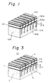
- FIG. 3 is a perspective view showing an embodiment of an ultrasound probe for a medical imaging system according to the present invention
- Fig. 4 is a partly diagrammatic sectional view showing an example of the ultrasound probe shown in Fig. 3.
- reference numeral 1 denotes a piezoelectric vibrator
- 2a and 2b denote electrodes
- 3 denotes an ultrasound absorber
- 4 denotes an acoustic matching layer
- 5 denotes a lead
- 6 denotes cutting grooves
- references d denotes a depth of the cutting groove in the ultrasound absorber
- Z denotes an acoustic impedance of the ultrasound absorber 4
- Z ' denotes an acoustic impedance of a cut portion in the ultrasound absorber 4.
- This configuration of the ultrasound probe of the present embodiment is same as the existing-type probe of Fig. 1.
- an acoustic velocity of a cut portion 7 of the ultrasound absorber 3 is lower than that of a non-cut portion thereof.
- an acoustic impedance Z' of the cut portion 7 is smaller than an acoustic impedance Z of the non-cut portion in the ultrasound absorber 3.
- This configuration is equivalent to a new layer of a depth d having an acoustic impedance Z', which is smaller than an acoustic impedance Z, being mounted to a rear of the piezoelectric vibrator 1.
- an ultrasound probe effectively includes a new acoustic matching layer located to the rear of the piezoelectric vibrator 1, and the new acoustic matching layer has a depth of d and an impedance of Z'.
- the depth d of the new rear acoustic matching layer is changed, frequency characteristics of the ultrasound probe are changed as shown in Figs. 5 to 8.
- Figure 5 is a diagram showing an example of gain-frequency characteristics of an ultrasound probe.
- a gain against a frequency in the case of the depth d of each of the cutting grooves 6 is determined to ranges of ⁇ /4 to ⁇ /2 (which is indicated by a solid line), and ⁇ /2 to 3 ⁇ /4 (which is indicated by a dot line) are shown.
- ⁇ /4 to ⁇ /2 which is indicated by a solid line
- ⁇ /2 to 3 ⁇ /4 which is indicated by a dot line
- the gain-frequency characteristics of the ultrasound probe are not symmetrical in relation to a center frequency f0 of ultrasound waves which are radiated from the piezoelectric vibrator 1 and corresponds to the wave length ⁇ .
- FIG. 6 is a diagram showing an example of gain-frequency characteristics of an ultrasound probe applicable to the present invention.
- a gain against a frequency in the case of the depth d of each of the cutting grooves 6 is determined to 0, ⁇ /4 and ⁇ /2.
- the gain-frequency characteristics of the ultrasound probe are symmetrical in regard to a center frequency f0 of ultrasound waves which are radiated from the piezoelectric vibrator 1 and correspond to the wave length ⁇ .
- n 0 implies no grooves are present, and is outside the scope of the present invention.
- a depth d of each of the cutting grooves 6 equals 1/4 ⁇
- a height of the gain G reaches a highest value
- a depth d of each of the cutting grooves 6 equals 1/2 ⁇
- a band width of the gain G reaches a broadest value.
- Figure 7 is a diagram showing an example of a relationship between a gain (an ultrasound radiation gain of a center frequency f0) G and a depth d of a groove 6 in an ultrasound probe.
- Figure 8 is a diagram showing an example of a relationship between a relative band width ( ⁇ f/f0) BW and a depth d of a groove 6 in an ultrasound probe.
- the relative band is a value that a band width ⁇ f at positions lower by -6dB than an gain G of the center frequency f0 divided by the center frequency f0, when a depth d of each of the cutting grooves 6 is changed to various values.
- the relative band width BW reaches a highest value.
- Electrodes 2a and 2b are mounted on to both sides of the piezoelectric vibrator 1.
- an acoustic matching layer 4 is mounted on to a front of the piezoelectric vibrator 1
- an ultrasound absorber 3 is mounted on to a rear of the piezoelectric vibrator 1.
- the ultrasound probe is cut from the acoustic matching layer 4 to the ultrasound absorber 3 through the piezoelectric vibrator 1 and the electrodes 2a and 2b by a plurality of cutting grooves 6.
- Figure 9 is a partly diagrammatic sectional view showing a modification of the ultrasound probe shown in Fig. 4.
- the cutting grooves 6 of the embodiment shown in Fig. 4 are formed only by a wide cutting portion, however, the cutting grooves 6a of the modification shown in Fig. 9 are formed by a wide cutting portion 61 and a narrow cutting portion 62.
- Such cutting grooves 6a of the modification of the ultrasound probe can have the same coefficients as the cutting grooves 6 in the embodiment shown in Fig. 4.
- a depth d of a cutting groove 6 in an ultrasound absorber 3 is determined by a positive integer times a 1/4 wave length ⁇ corresponding to a center frequency f0 of an ultrasound wave generated by the piezoelectric vibrator 1, and an array type ultrasound probe having preferable and stable ultrasound frequency characteristics, for example, a symmetrical configuration, a high efficiency and a broad relative band, can be provided.
Landscapes
- Engineering & Computer Science (AREA)
- Mechanical Engineering (AREA)
- Ultra Sonic Daignosis Equipment (AREA)
- Transducers For Ultrasonic Waves (AREA)
- Investigating Or Analyzing Materials By The Use Of Ultrasonic Waves (AREA)
Description
- The present invention relates to an ultrasound probe for a medical imaging system, more particularly, to an array type ultrasound probe.
- An ultrasound probe, which is used as an analog front end for a medical imaging system, provides a large number of independent channels, transduces electric signals to acoustic pressure, and generates sufficient acoustic energy to examine the various structures in the human body. Further, the ultrasound probe converts the weak returning acoustic echoes to a set of electrical signals which can be processed into an image.
- Typically, an ultrasound probe for a medical imaging system comprises an ultrasound absorber and a piezoelectric vibrator mounted on the ultrasound absorber, and is cut from the surface of the piezoelectric vibrator to the ultrasound absorber into the form of an array by a plurality of cutting grooves. Such an ultrasound probe is disclosed in Japanese Unexamined Patent Publication (Kokai) No. 58-118739.
- However, until now, a cutting depth d of each cutting groove has not been thought important, since a relationship between the cutting depth d and a gain has not been studied sufficiently. Therefore, symmetrical electro-acoustic conversion characteristics of the ultrasound probe cannot be satisfactorily obtained in frequency domain.
- An embodiment of the present invention may provide an ultrasound probe for a medical imaging system having preferable frequency characteristics by setting a depth d of each cutting groove in an ultrasound absorber to a specific value.
- According to the present invention, there is provided an ultrasound probe for a medical imaging system, having an ultrasound absorber, a first electrode mounted on the ultrasonic absorber, a piezoelectric vibrator mounted on said first electrode, and a second electrode mounted on said piezoelectric vibrator, wherein said ultrasound probe is cut into the form of an array by a plurality of cutting grooves extending from the outer surface of said second electrode, through said piezoelectric vibrator and said first electrode (2a) to said ultrasound absorber;
characterised in that:-
a cutting depth d of each groove is determined by

where λ is a wavelength corresponding to a center frequency fo of ultrasound waves radiated from said piezoelectric vibrator, and n is a positive integer. - The coefficient n may be an even number or an odd number.
- Reference is made, by way of example, to the accompanying drawings, in which:-
- Fig. 1 is a perspective view shgowing one example of an ultrasound probe for a medical imaging system;
- Fig. 2 is a block diagram showing an example of an ultrasound diagnostic apparatus using an ultrasound probe for a medical imaging system according to the present invention;
- Fig. 3 is a perspective view showing an embodiment of the ultrasound probe;
- Fig. 4 is a partly diagrammatic sectional view of the probe of Fig. 3;
- Figs. 5 and 6 are diagrams showing examples of gain-frequency characteristics of ultrasound probes;
- Fig. 7 is a diagram showing an example of a relationship between gain and groove depth in an ultrasound probe;
- Fig. 8 is a diagram showing an example of a relationship between relative band width and groove depth in an ultrasound probe; and
- Fig. 9 shows a modification of the ultrasound probe of Fig. 4.
- For a better understanding of the preferred embodiments, the problems of the related art will be first explained with reference to Fig. 1.
- The existing ultrasound probe comprises an ultrasound absorber 103, a
piezoelectric vibrator 101, a first and a second electrodes 102a and 102b, and anacoustic matching layer 104. Theultrasound absorber 103 is used for absorbing unnecessary (unwanted) ultrasound waves radiated from thepiezoelectric vibrator 101. Thepiezoelectric vibrator 101 is mounted on the ultrasound absorber 103 through the first electrode 102a, and theacoustic matching layer 104 is mounted on thepiezoelectric vibrator 101 through the second electrode 102b. Namely, thepiezoelectric vibrator 101 is positioned between the first electrode 102a and the second electrode 102b and driven by the first and second electrodes 102a and 102b. Note, theacoustic matching layer 104 is used for acoustic impedance matching between the human body and thepiezoelectric vibrator 101. 105 is a lead. - Further, the ultrasound probe is cut from the surface of the acoustic matching
layer 104 toward the ultrasound absorber 103 in the form of an array by a plurality ofcutting grooves 106. Note, a cutting depth of eachcutting groove 106 is not considered or a relationship between the cutting depth and a gain has not been studied sufficiently, and thus the depths of thecutting grooves 106 are scattered. In some cases, the ultrasound absorber 103 is deeply cut by thecutting grooves 106 out of necessity, and in other cases, theultrasound absorber 103 is shallowly cut or is not cut at all by thecutting grooves 106, and the depth of thecutting grooves 106 in theultrasound absorber 103 is not defined to be a specific value. Consequently, symmetrical electro-acoustic conversion characteristics of the existing ultrasound probe cannot be satisfied in the frequency domain. - Next, an ultrasound diagnostic apparatus using an ultrasound probe for a medical imaging system embodying the present invention will be explained.
- The ultrasound diagnostic apparatus is, for example, used for diagnosing a human body by using an ultrasound wave. Namely, the ultrasound diagnostic apparatus diagnoses internal organs or tumors of the human body by their shapes or acoustic characteristics thereof. Note, recently, the acoustic characteristics of tissues in the internal organs or tumors are, for example, characterized by an attenuation coefficient and a scattered coefficient. When the attenuation coefficient and the scattered coefficient are used in the ultrasound diagnostic apparatus, a pervasive disease or, e.g. cancer of a liver can be detected, furthermore, a myocardial infarction can be detected by the ultrasound diagnostic apparatus.
- Figure 2 is a block diagram showing an example of an ultrasound diagnostic apparatus using an ultrasound probe for a medical imaging system according to the present invention. In Fig. 2,
reference numerals 10 denotes an ultrasound probe, 11 denotes a transmitting amplifier, 12 denotes a receiving amplifier, 19 denotes a display, and references BS denotes a body surface and ROI denotes a region of interest. - The
ultrasound probe 10 is used for radiating an ultrasound beam to a region of interest ROI in a human body through the body surface BS, and receiving an ultrasound wave reflected by the region of interest ROI. The transmitting amplifier (which is an ultrasound pulser) 11 supplied with signals from atiming control portion 16, is used for driving theultrasound probe 10 by inputting pulse signals to theultrasound probe 10. Thereceiving amplifier 12 is used for amplifying the ultrasound wave signals received by theultrasound probe 10. An output signal of thereceiving amplifier 12 is supplied to a B-mode receiving circuit 13, a scatteredspectrum calculation portion 14, and a scatteredpower calculation portion 15, respectively. Note, the region of interest ROI is, for example, a part of internal organs, tumors, etc., which are suspected of a disease. - The B-
mode receiving circuit 13 generates a B-mode image by luminance signals corresponding to a signal strength of the reflected ultrasound wave signals output from thereceiving amplifier 12. An output signal of the B-mode receiving circuit 13 is supplied to thedisplay 19. The scatteredspectrum calculation portion 14 is used for calculating a scattered spectrum based on the ultrasound wave signals output from thereceiving amplifier 12. The scatteredpower calculation portion 15 is used for calculating a scattered ultrasound wave power based on the ultrasound wave signals output from thereceiving amplifier 12. - The
timing control portion 16 controls timings of various signals, and output signals of the timing control portion 26 are supplied to the scatteredpower calculation portion 15 and aROM 17. TheROM 17 is a read only memory for storing various data in response to addresses. The stored data of theROM 17 are, for example, scattered characteristics of the ultrasound beam, transmit and receive characteristics, and power transfer functions including frequency characteristics of the ultrasound diagnostic apparatus. - Output signals of the scattered
spectrum calculation portion 14, the scatteredpower calculation portion 15, and theROM 17 are supplied to acoefficient calculation portion 18. Thecoefficient calculation portion 18 is used for calculating an attenuation coefficient, a scattered coefficient, etc., and an output of thecoefficient calculation portion 18 is supplied to thedisplay 19. Consequently, thedisplay 19 is able to indicate both a B-mode picture image and a picture image characterized by the scattered coefficient and the attenuation coefficient. - Below, the preferred embodiments of the present invention will be explained with reference to Figs. 3 to 9.
- Figure 3 is a perspective view showing an embodiment of an ultrasound probe for a medical imaging system according to the present invention, and Fig. 4 is a partly diagrammatic sectional view showing an example of the ultrasound probe shown in Fig. 3. In Figs. 3 and 4,
reference numeral 1 denotes a piezoelectric vibrator, 2a and 2b denote electrodes, 3 denotes an ultrasound absorber, 4 denotes an acoustic matching layer, 5 denotes a lead, 6 denotes cutting grooves, and references d denotes a depth of the cutting groove in the ultrasound absorber, Z denotes an acoustic impedance of the ultrasound absorber 4, and Z ' denotes an acoustic impedance of a cut portion in the ultrasound absorber 4. - This configuration of the ultrasound probe of the present embodiment is same as the existing-type probe of Fig. 1. The difference between the present ultrasound probe and the Fig. 1 ultrasound probe exists in a cutting depth d of each
cutting groove 6. That is, the cutting depth d of each of the cutting grooves d in the ultrasound absorber 3 of the present invention is determined by the equation: d = n · ( λ / 4 ), where, the reference λ is a wave length corresponding to a center frequency f₀ of ultrasound waves radiated from the piezoelectric vibrator, and the coefficient n is a positive integer (1, 2, ...). - Below, an effect on frequency characteristics of an ultrasound probe of changing a depth d of each
cutting groove 6 will be explained. - In Figs. 3 and 4, when an ultrasound absorb 3 is cut by cutting
grooves 6 of depth d, an acoustic velocity of acut portion 7 of theultrasound absorber 3 is lower than that of a non-cut portion thereof. Further, an acoustic impedance Z' of thecut portion 7 is smaller than an acoustic impedance Z of the non-cut portion in theultrasound absorber 3. This configuration is equivalent to a new layer of a depth d having an acoustic impedance Z', which is smaller than an acoustic impedance Z, being mounted to a rear of thepiezoelectric vibrator 1. Therefore, an ultrasound probe according to the present embodiment effectively includes a new acoustic matching layer located to the rear of thepiezoelectric vibrator 1, and the new acoustic matching layer has a depth of d and an impedance of Z'. When the depth d of the new rear acoustic matching layer is changed, frequency characteristics of the ultrasound probe are changed as shown in Figs. 5 to 8. - Figure 5 is a diagram showing an example of gain-frequency characteristics of an ultrasound probe.
- In Fig. 5, a gain against a frequency in the case of the depth d of each of the cutting
grooves 6 is determined to ranges of λ/4 to λ/2 (which is indicated by a solid line), and λ/2 to 3λ/4 (which is indicated by a dot line) are shown. As indicated by these curves, when the depth d of each of the cuttinggrooves 6 is determined between the two specific values, a peak of the gain G tends to be in a high frequency direction or a low frequency direction and becomes asymmetrical. When the cutting depth d of each of the cuttinggrooves 6 is determined by the ranges: λ/4 < d < λ/2 or λ/2 < d < 3λ/4, the gain-frequency characteristics of the ultrasound probe are not symmetrical in relation to a center frequency f₀ of ultrasound waves which are radiated from thepiezoelectric vibrator 1 and corresponds to the wave length λ. - Figure 6 is a diagram showing an example of gain-frequency characteristics of an ultrasound probe applicable to the present invention. In Fig. 6, a gain against a frequency in the case of the depth d of each of the cutting
grooves 6 is determined to 0, λ/4 and λ/2. As indicated by these curves, when the depth d of each of the cuttinggrooves 6 is determined by an integer (which includes zero) times a 1/4 wave length λ , frequency characteristics become symmetrical. Namely, when a cutting depth d of each of the cuttinggrooves 6 is determined by the equation: d = n · ( λ/4 ), where, n = 0, 1, 2, ... ... , the gain-frequency characteristics of the ultrasound probe are symmetrical in regard to a center frequency f₀ of ultrasound waves which are radiated from thepiezoelectric vibrator 1 and correspond to the wave length λ . (Note: n = 0 implies no grooves are present, and is outside the scope of the present invention). Furthermore, when a depth d of each of the cuttinggrooves 6 equals 1/4 λ , a height of the gain G reaches a highest value, and when a depth d of each of the cuttinggrooves 6 equals 1/2 λ , a band width of the gain G reaches a broadest value. - Figure 7 is a diagram showing an example of a relationship between a gain (an ultrasound radiation gain of a center frequency f₀) G and a depth d of a
groove 6 in an ultrasound probe. - As indicated by this curve, when a depth d of each of the cutting
grooves 6 is determined to odd times of 1/4 λ , the gain G reaches a highest value. Namely, a cutting depth d of each of the cuttinggrooves 6 is determined by the equation: d = n · (λ/4), where, n = 1, 3, 5, ... ... , the gain G is positioned to a local maximum. - Figure 8 is a diagram showing an example of a relationship between a relative band width (Δf/f₀) BW and a depth d of a
groove 6 in an ultrasound probe. Note, the relative band is a value that a band width Δf at positions lower by -6dB than an gain G of the center frequency f₀ divided by the center frequency f₀, when a depth d of each of the cuttinggrooves 6 is changed to various values. As indicated by this curve, when a depth d of the cuttinggrooves 6 is determined to even times of 1/4 λ , the relative band width BW reaches a highest value. Namely, a cutting depth d of each of the cuttinggrooves 6 is determined by the equation: d = n · ( λ/4 ), where, n = 2, 4, 6, ... ..., the relative band width BW is positioned to a local maximum. - Therefore, an ultrasound probe having a symmetrical frequency characteristic can be provided by determining a depth d of each of the cutting
grooves 6 by the equation: d = n · ( λ/4 ), where, n = 1, 2, ... ... (i.e. a positive integer). If n is odd, an ultrasound probe having a symmetrical frequency characteristic and a high gain G can be provided. If n is even, an ultrasound probe having a symmetrical frequency characteristic and a high relative band width BW can be provided. - Next, a manufacturing method of an ultrasound probe will be described with reference to Fig. 3. First,
electrodes piezoelectric vibrator 1. Next, anacoustic matching layer 4 is mounted on to a front of thepiezoelectric vibrator 1, and anultrasound absorber 3 is mounted on to a rear of thepiezoelectric vibrator 1. Further, the ultrasound probe is cut from theacoustic matching layer 4 to theultrasound absorber 3 through thepiezoelectric vibrator 1 and theelectrodes grooves 6. - Figure 9 is a partly diagrammatic sectional view showing a modification of the ultrasound probe shown in Fig. 4. The cutting
grooves 6 of the embodiment shown in Fig. 4 are formed only by a wide cutting portion, however, the cuttinggrooves 6a of the modification shown in Fig. 9 are formed by awide cutting portion 61 and anarrow cutting portion 62.Such cutting grooves 6a of the modification of the ultrasound probe can have the same coefficients as the cuttinggrooves 6 in the embodiment shown in Fig. 4. - As described above, by means of the present invention, when a
piezoelectric vibrator 1 is divided in the form of an array type ultrasound probe, a depth d of a cuttinggroove 6 in anultrasound absorber 3 is determined by a positive integer times a 1/4 wave length λ corresponding to a center frequency f₀ of an ultrasound wave generated by thepiezoelectric vibrator 1, and an array type ultrasound probe having preferable and stable ultrasound frequency characteristics, for example, a symmetrical configuration, a high efficiency and a broad relative band, can be provided.
Claims (4)
- An ultrasound probe for a medical imaging system, having an ultrasound absorber (3), a first electrode (2a) mounted on the ultrasonic absorber (3), a piezoelectric vibrator (1) mounted on said first electrode (2a), and a second electrode (2b) mounted on said piezoelectric vibrator (1), wherein said ultrasound probe is cut into the form of an array by a plurality of cutting grooves (6) extending from the outer surface of said second electrode (2b) through said piezoelectric vibrator (1) and said first electrode (2a) to said ultrasound absorber (3);
characterised in that:-
a cutting depth d of each groove (6) is determined by

where λ is a wavelength corresponding to a center frequency f₀ of ultrasound waves radiated from said piezoelectric vibrator (1), and n is a positive integer. - An ultrasound probe according to claim 2, wherein n is even.
- An ultrasound probe according to claim 2, wherein n is odd.
- An ultrasound probe as claimed in claim 1, 2, or 3, further comprising an acoustic matching layer (4), mounted on said outer surface ofsaid second electrode (2b), for matching the ultrasound wave, and wherein said grooves (6) further extend through the whole thickness of said acoustic matching layer (4).
Applications Claiming Priority (2)
| Application Number | Priority Date | Filing Date | Title |
|---|---|---|---|
| JP122438/88 | 1988-05-19 | ||
| JP63122438A JP2615132B2 (en) | 1988-05-19 | 1988-05-19 | Ultrasonic probe |
Publications (3)
| Publication Number | Publication Date |
|---|---|
| EP0342874A2 EP0342874A2 (en) | 1989-11-23 |
| EP0342874A3 EP0342874A3 (en) | 1991-08-07 |
| EP0342874B1 true EP0342874B1 (en) | 1994-09-07 |
Family
ID=14835851
Family Applications (1)
| Application Number | Title | Priority Date | Filing Date |
|---|---|---|---|
| EP89304827A Expired - Lifetime EP0342874B1 (en) | 1988-05-19 | 1989-05-12 | Ultrasound probe for medical imaging system |
Country Status (5)
| Country | Link |
|---|---|
| US (1) | US4992989A (en) |
| EP (1) | EP0342874B1 (en) |
| JP (1) | JP2615132B2 (en) |
| AU (1) | AU604408B2 (en) |
| DE (1) | DE68917985T2 (en) |
Cited By (1)
| Publication number | Priority date | Publication date | Assignee | Title |
|---|---|---|---|---|
| DE29708338U1 (en) * | 1997-05-12 | 1998-09-17 | DWL Elektronische Systeme GmbH, 78354 Sipplingen | Multifrequency ultrasound probe |
Families Citing this family (58)
| Publication number | Priority date | Publication date | Assignee | Title |
|---|---|---|---|---|
| US5005054A (en) * | 1990-07-02 | 1991-04-02 | Xerox Corporation | Frequency sweeping excitation of high frequency vibratory energy producing devices for electrophotographic imaging |
| US5025291A (en) * | 1990-07-02 | 1991-06-18 | Zerox Corporation | Edge effect compensation in high frequency vibratory energy producing devices for electrophotographic imaging |
| US5010369A (en) * | 1990-07-02 | 1991-04-23 | Xerox Corporation | Segmented resonator structure having a uniform response for electrophotographic imaging |
| US5611343A (en) * | 1995-04-05 | 1997-03-18 | Loral Aerospace Corp. | High resolution three-dimensional ultrasound imaging |
| US5655538A (en) * | 1995-06-19 | 1997-08-12 | General Electric Company | Ultrasonic phased array transducer with an ultralow impedance backfill and a method for making |
| US6050943A (en) | 1997-10-14 | 2000-04-18 | Guided Therapy Systems, Inc. | Imaging, therapy, and temperature monitoring ultrasonic system |
| US6623430B1 (en) | 1997-10-14 | 2003-09-23 | Guided Therapy Systems, Inc. | Method and apparatus for safety delivering medicants to a region of tissue using imaging, therapy and temperature monitoring ultrasonic system |
| US7914453B2 (en) | 2000-12-28 | 2011-03-29 | Ardent Sound, Inc. | Visual imaging system for ultrasonic probe |
| CN100399596C (en) * | 2003-03-12 | 2008-07-02 | 中国科学院声学研究所 | Phased Array Probes for Scanning Imaging Setups |
| US7393325B2 (en) | 2004-09-16 | 2008-07-01 | Guided Therapy Systems, L.L.C. | Method and system for ultrasound treatment with a multi-directional transducer |
| US9011336B2 (en) | 2004-09-16 | 2015-04-21 | Guided Therapy Systems, Llc | Method and system for combined energy therapy profile |
| US7824348B2 (en) | 2004-09-16 | 2010-11-02 | Guided Therapy Systems, L.L.C. | System and method for variable depth ultrasound treatment |
| US7530958B2 (en) * | 2004-09-24 | 2009-05-12 | Guided Therapy Systems, Inc. | Method and system for combined ultrasound treatment |
| US8444562B2 (en) | 2004-10-06 | 2013-05-21 | Guided Therapy Systems, Llc | System and method for treating muscle, tendon, ligament and cartilage tissue |
| US8535228B2 (en) | 2004-10-06 | 2013-09-17 | Guided Therapy Systems, Llc | Method and system for noninvasive face lifts and deep tissue tightening |
| US10864385B2 (en) | 2004-09-24 | 2020-12-15 | Guided Therapy Systems, Llc | Rejuvenating skin by heating tissue for cosmetic treatment of the face and body |
| ES2630221T3 (en) | 2004-10-06 | 2017-08-18 | Guided Therapy Systems, L.L.C. | Procedure and system for the treatment of tissues by ultrasound |
| US11235179B2 (en) | 2004-10-06 | 2022-02-01 | Guided Therapy Systems, Llc | Energy based skin gland treatment |
| US9827449B2 (en) | 2004-10-06 | 2017-11-28 | Guided Therapy Systems, L.L.C. | Systems for treating skin laxity |
| EP1879502A2 (en) * | 2004-10-06 | 2008-01-23 | Guided Therapy Systems, L.L.C. | Method and system for cosmetic enhancement |
| US9694212B2 (en) | 2004-10-06 | 2017-07-04 | Guided Therapy Systems, Llc | Method and system for ultrasound treatment of skin |
| US8133180B2 (en) | 2004-10-06 | 2012-03-13 | Guided Therapy Systems, L.L.C. | Method and system for treating cellulite |
| US11883688B2 (en) | 2004-10-06 | 2024-01-30 | Guided Therapy Systems, Llc | Energy based fat reduction |
| US8690778B2 (en) | 2004-10-06 | 2014-04-08 | Guided Therapy Systems, Llc | Energy-based tissue tightening |
| US7758524B2 (en) | 2004-10-06 | 2010-07-20 | Guided Therapy Systems, L.L.C. | Method and system for ultra-high frequency ultrasound treatment |
| US20060111744A1 (en) | 2004-10-13 | 2006-05-25 | Guided Therapy Systems, L.L.C. | Method and system for treatment of sweat glands |
| US11207548B2 (en) | 2004-10-07 | 2021-12-28 | Guided Therapy Systems, L.L.C. | Ultrasound probe for treating skin laxity |
| US11724133B2 (en) | 2004-10-07 | 2023-08-15 | Guided Therapy Systems, Llc | Ultrasound probe for treatment of skin |
| EP1875327A2 (en) | 2005-04-25 | 2008-01-09 | Guided Therapy Systems, L.L.C. | Method and system for enhancing computer peripheral saftey |
| RU2294061C1 (en) * | 2005-06-14 | 2007-02-20 | Государственное образовательное учреждение высшего профессионального образования "Ростовский Государственный Университет" (РГУ) | Multicomponent piezoelectric transducer and its manufacturing process |
| US9566454B2 (en) * | 2006-09-18 | 2017-02-14 | Guided Therapy Systems, Llc | Method and sysem for non-ablative acne treatment and prevention |
| WO2008137942A1 (en) | 2007-05-07 | 2008-11-13 | Guided Therapy Systems, Llc. | Methods and systems for modulating medicants using acoustic energy |
| US20150174388A1 (en) | 2007-05-07 | 2015-06-25 | Guided Therapy Systems, Llc | Methods and Systems for Ultrasound Assisted Delivery of a Medicant to Tissue |
| JP5358078B2 (en) * | 2007-10-01 | 2013-12-04 | 日立アロカメディカル株式会社 | Ultrasonic probe |
| JP2009082612A (en) * | 2007-10-02 | 2009-04-23 | Toshiba Corp | Ultrasonic probe and piezoelectric vibrator |
| US12102473B2 (en) | 2008-06-06 | 2024-10-01 | Ulthera, Inc. | Systems for ultrasound treatment |
| US10537304B2 (en) | 2008-06-06 | 2020-01-21 | Ulthera, Inc. | Hand wand for ultrasonic cosmetic treatment and imaging |
| EP2382010A4 (en) | 2008-12-24 | 2014-05-14 | Guided Therapy Systems Llc | Methods and systems for fat reduction and/or cellulite treatment |
| US8715186B2 (en) | 2009-11-24 | 2014-05-06 | Guided Therapy Systems, Llc | Methods and systems for generating thermal bubbles for improved ultrasound imaging and therapy |
| US9504446B2 (en) | 2010-08-02 | 2016-11-29 | Guided Therapy Systems, Llc | Systems and methods for coupling an ultrasound source to tissue |
| WO2012018386A2 (en) | 2010-08-02 | 2012-02-09 | Guided Therapy Systems, Llc | Systems and methods for ultrasound treatment |
| US8857438B2 (en) | 2010-11-08 | 2014-10-14 | Ulthera, Inc. | Devices and methods for acoustic shielding |
| JP5725978B2 (en) * | 2011-06-02 | 2015-05-27 | 株式会社東芝 | Ultrasonic probe |
| EP2729215A4 (en) | 2011-07-10 | 2015-04-15 | Guided Therapy Systems Llc | Methods and systems for ultrasound treatment |
| US9011337B2 (en) | 2011-07-11 | 2015-04-21 | Guided Therapy Systems, Llc | Systems and methods for monitoring and controlling ultrasound power output and stability |
| US9263663B2 (en) | 2012-04-13 | 2016-02-16 | Ardent Sound, Inc. | Method of making thick film transducer arrays |
| US9510802B2 (en) | 2012-09-21 | 2016-12-06 | Guided Therapy Systems, Llc | Reflective ultrasound technology for dermatological treatments |
| CN204017181U (en) | 2013-03-08 | 2014-12-17 | 奥赛拉公司 | Aesthetic imaging and treatment system, multifocal treatment system and system for performing cosmetic procedures |
| US10561862B2 (en) | 2013-03-15 | 2020-02-18 | Guided Therapy Systems, Llc | Ultrasound treatment device and methods of use |
| JP2017513587A (en) | 2014-04-18 | 2017-06-01 | ウルセラ インコーポレイテッド | Band transducer ultrasound therapy |
| RU2720661C2 (en) | 2016-01-18 | 2020-05-12 | Ультера, Инк. | Compact ultrasonic device comprising an annular ultrasonic matrix electrically connected in periphery with a flexible printed circuit board, and a method of assembling such a device |
| RU2748788C2 (en) | 2016-08-16 | 2021-05-31 | Ультера, Инк. | Systems and methods for cosmetic ultrasonic skin treatment |
| TWI883390B (en) | 2018-01-26 | 2025-05-11 | 美商奧賽拉公司 | Systems and methods for simultaneous multi-focus ultrasound therapy in multiple dimensions |
| WO2019164836A1 (en) | 2018-02-20 | 2019-08-29 | Ulthera, Inc. | Systems and methods for combined cosmetic treatment of cellulite with ultrasound |
| AU2019385902B2 (en) | 2018-11-30 | 2025-07-10 | Ulthera, Inc. | Systems and methods for enhancing efficacy of ultrasound treatment |
| BR112022000062A2 (en) | 2019-07-15 | 2022-06-07 | Ulthera Inc | Systems and methods for measuring elasticity with multifocal ultrasound imaging of multifocal shear waves in multiple dimensions |
| CN112353419B (en) * | 2020-11-30 | 2024-03-15 | 中国科学院苏州生物医学工程技术研究所 | Multi-array element scanning type ultrasonic probe, ultrasonic imaging system and ultrasonic imaging method |
| GB202019016D0 (en) * | 2020-12-02 | 2021-01-13 | Ionix Advanced Tech Ltd | Transducer and method of manufacture |
Family Cites Families (7)
| Publication number | Priority date | Publication date | Assignee | Title |
|---|---|---|---|---|
| DE3069001D1 (en) * | 1979-05-16 | 1984-09-27 | Toray Industries | Piezoelectric vibration transducer |
| JPS56161799A (en) * | 1980-05-15 | 1981-12-12 | Matsushita Electric Ind Co Ltd | Ultrasonic wave probe |
| JPS58118739A (en) * | 1982-01-05 | 1983-07-14 | テルモ株式会社 | Ultasonic probe and production thereof |
| JPS58195552A (en) * | 1982-05-10 | 1983-11-14 | 松下電器産業株式会社 | ultrasonic probe |
| JPS5999900A (en) * | 1982-11-29 | 1984-06-08 | Toshiba Corp | Ultrasonic wave probe |
| JPS60196688A (en) * | 1984-03-19 | 1985-10-05 | Hitachi Medical Corp | Scanning type ultrasonic wave apparatus |
| US4671293A (en) * | 1985-10-15 | 1987-06-09 | North American Philips Corporation | Biplane phased array for ultrasonic medical imaging |
-
1988
- 1988-05-19 JP JP63122438A patent/JP2615132B2/en not_active Expired - Fee Related
-
1989
- 1989-05-02 US US07/346,527 patent/US4992989A/en not_active Expired - Lifetime
- 1989-05-05 AU AU34092/89A patent/AU604408B2/en not_active Ceased
- 1989-05-12 DE DE68917985T patent/DE68917985T2/en not_active Expired - Fee Related
- 1989-05-12 EP EP89304827A patent/EP0342874B1/en not_active Expired - Lifetime
Cited By (1)
| Publication number | Priority date | Publication date | Assignee | Title |
|---|---|---|---|---|
| DE29708338U1 (en) * | 1997-05-12 | 1998-09-17 | DWL Elektronische Systeme GmbH, 78354 Sipplingen | Multifrequency ultrasound probe |
Also Published As
| Publication number | Publication date |
|---|---|
| EP0342874A2 (en) | 1989-11-23 |
| AU604408B2 (en) | 1990-12-13 |
| JP2615132B2 (en) | 1997-05-28 |
| US4992989A (en) | 1991-02-12 |
| JPH01291840A (en) | 1989-11-24 |
| AU3409289A (en) | 1989-11-23 |
| EP0342874A3 (en) | 1991-08-07 |
| DE68917985T2 (en) | 1995-02-09 |
| DE68917985D1 (en) | 1994-10-13 |
Similar Documents
| Publication | Publication Date | Title |
|---|---|---|
| EP0342874B1 (en) | Ultrasound probe for medical imaging system | |
| US4507582A (en) | Matching region for damped piezoelectric ultrasonic apparatus | |
| EP0404154B1 (en) | Ultrasonic probe having backing material layer of uneven thickness | |
| US6540677B1 (en) | Ultrasound transceiver system for remote operation through a minimal number of connecting wires | |
| CA1130439A (en) | Ultrasonic transducer array | |
| US5678554A (en) | Ultrasound transducer for multiple focusing and method for manufacture thereof | |
| US4241611A (en) | Ultrasonic diagnostic transducer assembly and system | |
| JP4242472B2 (en) | Ultrasonic transducer array and ultrasonic imaging system | |
| US20030055337A1 (en) | Dual-frequency ultrasonic array transducer and method of harmonic imaging | |
| US4870972A (en) | Multiple-frequency acoustic transducer, especially for medical imaging | |
| US5296777A (en) | Ultrasonic probe | |
| GB2079456A (en) | Extended focus transducer system | |
| GB2117905A (en) | Ultrasonic imaging apparatus | |
| EP0110378B2 (en) | Ultrasonic probe | |
| DE3382720T2 (en) | Electroacoustic transducer and a probe or diagnostic ultrasound device with such a transducer. | |
| JPS58135977A (en) | Ultrasonic linear array transducer with collimator | |
| Ylitalo | On the signal-to-noise ratio of a synthetic aperture ultrasound imaging method | |
| US6312386B1 (en) | Medical ultrasound imaging system with composite delay profile | |
| EP1815795B1 (en) | Ultrasonographic device | |
| JPS649012B2 (en) | ||
| JP3468678B2 (en) | Ultrasonic probe | |
| JPH0226189B2 (en) | ||
| Frizzell et al. | Ultrasound phased arrays for hyperthermia treatment | |
| JP3644876B2 (en) | Ultrasonic probe and ultrasonic diagnostic apparatus | |
| Karrer et al. | A phased array acoustic imaging system for medical use |
Legal Events
| Date | Code | Title | Description |
|---|---|---|---|
| PUAI | Public reference made under article 153(3) epc to a published international application that has entered the european phase |
Free format text: ORIGINAL CODE: 0009012 |
|
| AK | Designated contracting states |
Kind code of ref document: A2 Designated state(s): DE FR GB |
|
| PUAL | Search report despatched |
Free format text: ORIGINAL CODE: 0009013 |
|
| AK | Designated contracting states |
Kind code of ref document: A3 Designated state(s): DE FR GB |
|
| 17P | Request for examination filed |
Effective date: 19910912 |
|
| 17Q | First examination report despatched |
Effective date: 19930405 |
|
| GRAA | (expected) grant |
Free format text: ORIGINAL CODE: 0009210 |
|
| AK | Designated contracting states |
Kind code of ref document: B1 Designated state(s): DE FR GB |
|
| REF | Corresponds to: |
Ref document number: 68917985 Country of ref document: DE Date of ref document: 19941013 |
|
| ET | Fr: translation filed | ||
| PLBE | No opposition filed within time limit |
Free format text: ORIGINAL CODE: 0009261 |
|
| STAA | Information on the status of an ep patent application or granted ep patent |
Free format text: STATUS: NO OPPOSITION FILED WITHIN TIME LIMIT |
|
| 26N | No opposition filed | ||
| REG | Reference to a national code |
Ref country code: FR Ref legal event code: TP |
|
| REG | Reference to a national code |
Ref country code: GB Ref legal event code: 732E |
|
| REG | Reference to a national code |
Ref country code: GB Ref legal event code: IF02 |
|
| PGFP | Annual fee paid to national office [announced via postgrant information from national office to epo] |
Ref country code: GB Payment date: 20030507 Year of fee payment: 15 |
|
| PGFP | Annual fee paid to national office [announced via postgrant information from national office to epo] |
Ref country code: FR Payment date: 20030508 Year of fee payment: 15 |
|
| PGFP | Annual fee paid to national office [announced via postgrant information from national office to epo] |
Ref country code: DE Payment date: 20030522 Year of fee payment: 15 |
|
| PG25 | Lapsed in a contracting state [announced via postgrant information from national office to epo] |
Ref country code: GB Free format text: LAPSE BECAUSE OF NON-PAYMENT OF DUE FEES Effective date: 20040512 |
|
| PG25 | Lapsed in a contracting state [announced via postgrant information from national office to epo] |
Ref country code: DE Free format text: LAPSE BECAUSE OF NON-PAYMENT OF DUE FEES Effective date: 20041201 |
|
| GBPC | Gb: european patent ceased through non-payment of renewal fee |
Effective date: 20040512 |
|
| PG25 | Lapsed in a contracting state [announced via postgrant information from national office to epo] |
Ref country code: FR Free format text: LAPSE BECAUSE OF NON-PAYMENT OF DUE FEES Effective date: 20050131 |
|
| REG | Reference to a national code |
Ref country code: FR Ref legal event code: ST |