EP0342837A1 - Vorrichtung zur elektrolytischen Behandlung von Artikeln - Google Patents
Vorrichtung zur elektrolytischen Behandlung von Artikeln Download PDFInfo
- Publication number
- EP0342837A1 EP0342837A1 EP89304612A EP89304612A EP0342837A1 EP 0342837 A1 EP0342837 A1 EP 0342837A1 EP 89304612 A EP89304612 A EP 89304612A EP 89304612 A EP89304612 A EP 89304612A EP 0342837 A1 EP0342837 A1 EP 0342837A1
- Authority
- EP
- European Patent Office
- Prior art keywords
- workpiece
- carrier wheel
- carrier
- treatment apparatus
- electrolytic treatment
- Prior art date
- Legal status (The legal status is an assumption and is not a legal conclusion. Google has not performed a legal analysis and makes no representation as to the accuracy of the status listed.)
- Withdrawn
Links
- 238000011282 treatment Methods 0.000 title claims description 35
- 238000004070 electrodeposition Methods 0.000 claims abstract description 59
- 239000003792 electrolyte Substances 0.000 claims abstract description 44
- 238000012360 testing method Methods 0.000 claims abstract description 12
- 239000000969 carrier Substances 0.000 claims description 45
- 230000002093 peripheral effect Effects 0.000 claims description 25
- 239000012530 fluid Substances 0.000 claims description 21
- 230000005291 magnetic effect Effects 0.000 claims description 19
- 239000002184 metal Substances 0.000 claims description 12
- 239000000463 material Substances 0.000 claims description 8
- 230000005294 ferromagnetic effect Effects 0.000 claims description 3
- 230000000295 complement effect Effects 0.000 claims description 2
- 230000001419 dependent effect Effects 0.000 claims 2
- 238000000576 coating method Methods 0.000 description 8
- 239000011248 coating agent Substances 0.000 description 6
- 238000000034 method Methods 0.000 description 6
- 230000008569 process Effects 0.000 description 6
- 239000011324 bead Substances 0.000 description 5
- 230000008901 benefit Effects 0.000 description 3
- CWYNVVGOOAEACU-UHFFFAOYSA-N Fe2+ Chemical compound [Fe+2] CWYNVVGOOAEACU-UHFFFAOYSA-N 0.000 description 2
- 235000013361 beverage Nutrition 0.000 description 2
- 230000000694 effects Effects 0.000 description 2
- 238000004519 manufacturing process Methods 0.000 description 2
- 238000012544 monitoring process Methods 0.000 description 2
- 238000003860 storage Methods 0.000 description 2
- 230000001360 synchronised effect Effects 0.000 description 2
- 230000008859 change Effects 0.000 description 1
- 238000010276 construction Methods 0.000 description 1
- 230000007812 deficiency Effects 0.000 description 1
- 238000010586 diagram Methods 0.000 description 1
- 238000001962 electrophoresis Methods 0.000 description 1
- 238000009713 electroplating Methods 0.000 description 1
- 230000002349 favourable effect Effects 0.000 description 1
- 238000013101 initial test Methods 0.000 description 1
- 239000011810 insulating material Substances 0.000 description 1
- 239000000696 magnetic material Substances 0.000 description 1
- 238000012986 modification Methods 0.000 description 1
- 230000004048 modification Effects 0.000 description 1
- 239000011368 organic material Substances 0.000 description 1
- 238000003825 pressing Methods 0.000 description 1
- 230000001681 protective effect Effects 0.000 description 1
- 238000004080 punching Methods 0.000 description 1
- 230000008439 repair process Effects 0.000 description 1
- 239000012260 resinous material Substances 0.000 description 1
- 238000005096 rolling process Methods 0.000 description 1
Images

Classifications
-
- C—CHEMISTRY; METALLURGY
- C25—ELECTROLYTIC OR ELECTROPHORETIC PROCESSES; APPARATUS THEREFOR
- C25D—PROCESSES FOR THE ELECTROLYTIC OR ELECTROPHORETIC PRODUCTION OF COATINGS; ELECTROFORMING; APPARATUS THEREFOR
- C25D7/00—Electroplating characterised by the article coated
- C25D7/04—Tubes; Rings; Hollow bodies
-
- C—CHEMISTRY; METALLURGY
- C25—ELECTROLYTIC OR ELECTROPHORETIC PROCESSES; APPARATUS THEREFOR
- C25D—PROCESSES FOR THE ELECTROLYTIC OR ELECTROPHORETIC PRODUCTION OF COATINGS; ELECTROFORMING; APPARATUS THEREFOR
- C25D13/00—Electrophoretic coating characterised by the process
- C25D13/12—Electrophoretic coating characterised by the process characterised by the article coated
- C25D13/14—Tubes; Rings; Hollow bodies
Definitions
- This invention relates to electrolytic treatment apparatus for electrolytically treating disc-like metal workpieces, and particularly but not exclusively to such apparatus for electro-phoretically coating (electro-coating) workpieces such as can ends for use in the manufacture of metal cans for food and beverage storage.
- Patent specification GB 1,361,657 discloses an apparatus for electro-coating circular metal parts having raw, cut edges, such as can ends, with a resinous, organic coating material. That apparatus comprises an electro-coating bath for containing the resinous organic material; an electrically energisable first guide member situated above the electro-coating bath; and a non-conducting, second guide member disposed in the bath.
- the guide members define a pair of vertically aligned grooves for receiving and guiding can ends which are rolled on edge between them by virtue of the movement of one of the guide members.
- the movable guide member comprises either a endless belt, or alternatively the periphery of a rotatable wheel.
- the groove in the energisable guide member is shaped so as to effect a rolling, wiping electrical contact with the raw, cud edge of each can end, so that as each can end progresses through the bath of coating material, it becomes electro-phoretically coated with resinous material.
- the can ends act as anodes to a cathode immersed in the bath of coating material.
- Patent specification US 4,659,445 discloses an apparatus for electro-coating metal can bodies.
- can bodies are loaded on to the peripheral parts of a rotatable carrier wheel which has its lower portion submerged in an electro-coating fluid contained in a tank below the carrier wheel. Rotation of the wheel carries each can body in turn down into, through and out of the electro-coating fluid. Whilst each can body is submerged in the electro-coating fluid, electro-coating material is deposited on the can body by virtue of the electrical energisation of the carrier wheel and the can bodies carried thereon relative to a counter electrode which is likewise submerged in the electro-coating fluid.
- the carrier wheel shaft is submerged in the electro-coating fluid, and the can bodies are gripped at their open ends by mechanical grippers carried by the carrier wheel, with the open ends of the can bodies facing radially inwards.
- the carrier wheel shaft is disposed wholly above the free surface of the electro-coating fluid, and the can bodies are held magnetically at their closed ends by magnetic carriers which are pivotally secured on the carrier wheel, and which are pivoted as the carrier wheel rotates so as reverse the disposition of the can bodies, so that their open ends face radially inwards.
- all of the can bodies carried into the electro-coating fluid are energised simultaneously and in a parallel manner whilst in the fluid, so that it is not possible to monitor and control the electro-coating of the respective individual can bodies, whereby to ensure uniform electro-coating of the respective can bodies.
- the present invention seeks to overcome this deficiency, and thus to provide an apparatus in which the electro-coating of each successive can body can be individually monitored and controlled to achieve the desired electro-coating of each specific can body.
- the present invention is concerned with an electrolytic treatment apparatus for electrolytically treating metal workpieces, which apparatus comprises:
- such an apparatus is characterised in that -
- each slipring is electrically conductive over only a predetermined circumferential portion of its peripheral surface, which portion is positioned in relationship to the associated workpiece carrier and the associated brush so as to electrically energise the associated workpiece carrier only during its travel below the electrolyte surface level during each revolution of the carrier wheel, a complementary circumferential portion of the slipring peripheral surface being electrically non-conductive.
- each conductive surface portion of a slipring is of such circumferential length that the associated workpiece carrier is energised for substantially the whole of the travel of that workpiece carrier below the electrolyte surface level during each revolution of the carrier wheel.
- each of a plurality of selected sliprings may conveniently be replaced, in part, by one or more correspondingly-positioned conductive surface portions of other such sliprings, thereby (a) to energise two or more workpiece carriers in spaced succession from each selected slipring and its associated brush during each revolution of the carrier wheel, and (b) to reduce the number of separate sliprings and associated brushes otherwise required for energising the workpiece carriers.
- the carrier wheel carries 'x.N' workpiece carriers ('x' and 'N' both being integral), and (b) the electrolyte surface level is positioned such that at least 'N' workpiece carriers lie below the electrolyte surface level, maximum advantage is obtained when 'N' sliprings, each having 'x' conductive porions, are used.
- 'x' has the value '3'.
- An electrolytic treatment apparatus may also include any suitable combination of the optional features set out below:
- Electrolytic treatment apparatus may include a filling of an electro-coating fluid reaching up to the said electrolyte surface level, and be used for electro-coating disc-like metal workpieces.
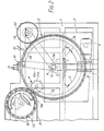
- the apparatus there shown comprises a frame 1 which supports an electrolyte tank 2, and above it, a rotatable carrier wheel 3. That wheel is carried for rotation on a driving shaft 4 which is mounted in bearings 5 carried on the frame 1. Only the lower part of the carrier wheel3 dips down below the free surface level 'L' (see Figure 2) of an electro-coating fluid contained in the tank 2.
- the driving shaft 4 is coupled through a speed reducing gear box 6 to an electric driving motor 7.
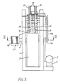
- the carrier wheel 3 has secured around its peripheral portion two parallel circles of workpiece carriers (or pallets) 8 of a conductive metal. Each such pallet incorporates a circular aperture 9 which constitutes a workpiece pocket for receiving workpieces in the form of 'can ends' for use in the manufacture of metal cans for food and beverage storage. Such can ends are generally disc-like and are fed to the respective pockets, as the carrier wheel rotates, by a workpiece feeding unit 10. That unit, driven by a belt 10A from the carrier wheel shaft 4, includes two vertical stacks of can ends confined by groups of upright rods 11, and is arranged to feed the bottom can end from each such stack into the next free workpiece pocket as it comes into line with the stack.
- each detector supplies an output signal to a control unit 33 (shown in Figure 5) indicative of the presence or absence of a workpiece in a pallet passing thereby. That signal is stored in the control unit 33.
- a 'can end absent' signal acts to inhibit the later energisation of an empty pallet when slipring control means (likewise shown in Figure 5 and to be described later) signifies that that pallet has become submerged in the electro-coating bath and should be energised to effect electro-coating.
- each pair of adjacent pallets in turn to pass below respective pressure rolls 13, which are driven by a belt 13A from the carrier wheel shaft 4 and which press the workpieces lodged in the respective pockets 9 more firmly into position in those pockets.
- Arcuate magnetic rails 14 disposed concentrically with and radially inwards of the pallets 8 assist in positioning ferrous workpieces by magnetically pulling them firmly into good electrical contact with annular contact surfaces provided by upstanding beads 28 formed in the respective pockets 9.
- the control unit 33 performs an electrical circuit resistance test so as to ascertain whether circuit conditions satisfactory for the commencement of the electro-coating process exist, i.e whether the workpiece is in good electrical contact with the pocket in which it is disposed.
- the electro-coating process is carried out, under the control of the control unit 33 and the slipring control means, during rotation of the carrier wheel 3 through an angle which has as a maximum value the angle designated 'C' in Figure 2, that is before the workpiece is lifted out of the electro-coating fluid.
- a workpiece outfeed device which comprises a magnetic belt 15 carried on a driving pulley wheel 16.
- the latter device is synchronised to the carrier wheel shaft 4 by electrical or mechanical means not shown.
- the magnetic influence of the counter electrode rails 14 is overcome and the coated workpieces are magnetically attracted to and are carried away by the magnetic belt 15.
- the apparatus described above can be used for a variety of electro-coating treatments, and with a suitable change of electolyte, for various other electrolytic treatments, such as electro-plating.
- Such apparatus is particularly suited to the application (by electro-phoresis) of repair coatings to metal can ends after they have been produced by mechanical punching and pressing operations from metal feedstock sheet, which may have been pre-coated, or un-coated.
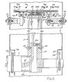
- FIG. 4 shows in detail the various parts of the carrier wheel 3 and the tank 2 which participate in the electro-coating process.
- the carrier wheel 3 comprises a pair of axially spaced annular plates or discs 19A, 19B which are secured by bolts 20 to a hub 21 which forms part of the carrier wheel shaft 4.
- the two plates 19A, 19B are secured by bolts to opposite ends of a short, thick-walled, generally cylindrical, peripheral member 22 (which in the embodiment shown is constituted by a plurality of plane, axial segments disposed circumferentially adjacent one another), and define between them an annular cavity.
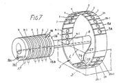
- That cavity commumicates through radial holes 21A formed in periphery of the hub with the bore 4A of the non-driving part of the shaft 4, which part carries outboard of the tank 2 a slipring assembly which comprises a set of sliprings 18 carried on an insulating tubular support 34 (see Figures 5 and 6).
- That shaft is provided inboard of the respective side walls of the tank 2 with respective flinger wheels 23 which are enclosed in cowls 24 for catching and returning to the electrolyte bath any electrolyte flying off the flinger wheels.
- the respective workpiece carriers 8 are denoted in Figure 4 by the references 8A and 8B respectively, and are shown secured by metal studs 25, 25B which extend in an electrically insulated manner through radial holes formed in the respective segments constituting the peripheral member 22 and which are held captive in electrical connectors 26.
- Those connectors are themselves secured in an insulated manner in axial holes formed in the respective segments constituting the peripheral member 22, and have radial holes in which the ends of respective cables 27 are disposed and clamped by grub screws 26A.
- Those cables extend in a fluid-tight manner through the radial holes 21A in the hub 21, and then extend along the dry bore 4A of the shaft 4 to the slipring assembly carried at the end of that shaft.
- connection studs 18A which protude axially from the slipring assembly and are connected with respective conducting segments 18B of the various sliprings 18.
- the workpiece carriers 8A and 8B are shown in Figure 4 as being of different sizes, and are intended to receive workpieces of correspondingly different sizes. However, if desired, the workpiece carriers may be replaced by other such carriers intended to receive other workpieces of equal sizes.
- the pallet 8B is shown in Figure 4 as confining the periphery of a can end 29. Actual electrical contact with the can end is made between the raw, cut edge of the can end 29 and an annular contact surface of a bead 28 which reaches up inside the peripheral curled part of the can end.
- the arcuate rails 14 act as both (a) magnetic retaining means to hold the can ends 29 in contact with the pocket beads 28, and (b) as cathodes, being negatively energised relative to the adjacent circle of pallets 8 and can ends 29.
- Those rails are supported in the tank 2 by electrical terminal blocks 30 which are themselves carried in electrically insulating grommets 31 which extend through the wall of the tank. Cables 32 connect the terminal blocks 30 with the control unit 33 shown in the Figure 5.
- the magnetic rail may be clothed in a corrosion-proof protective sheath, and an exposed arcuate electrode may be provided alongside the sheathed magnetic rail.
- arcuate cathodes 14A may be placed alongside each arcuate rail 14 (which then serves only as a magnetic retaining means) radially inwards of the pallets 8A and 8B, whilst other pairs of arcuate cathodes 14B may be placed radially outwards of the pallets 8A and 8B.
- the control unit 33 is arranged to receive control signals from the respective can end detectors 12. As mentioned earlier, if such a detector provides a 'can end absent' signal, the control unit 33 is inhibited from energising the relevant pallet 9 at the appropriate later time. On the other hand, in the presence of a 'can end present' signal from a detector 12, the control unit 33 passes temporarily a small test current to the relevant pallet 8 to ascertain whether the workpiece is in good electrical contact with the annular bead 28 in the pallet.
- the control unit 33 If the test indicates that the workpiece is in good electrical contact with its pallet, the control unit 33 fully energises the pallet and workpiece relative to the adjacent cathode rail 14, via the appropriate slipring 18, to electro-coat the can end. If for some reason, a workpiece is incorrectly seated in the pallet pocket, the resultant test signal inhibits the control unit 33 so that it is unable to supply an electro-coating current to the pallet.
- each pallet 8 remains submerged in the electro-coating fluid for approximately one third of a carrier wheel revolution, and no benefit derives from energising a pallet when it is not so submerged, it is possible in a more compact slipring assembly to energise a pallet from one of three similar arcuate conductive segments 18B which together form a single slipring 18.
- Each such segment 18B is electrically insulated from the others, and spans approximately one third of the circumference of the slipring.
- the three segments of each such slipring are electrically connected with respective pallets 8 that lie spaced apart on the carrier wheel at an angular pitch of 120°, and corresponding segments in adjacent sliprings are staggered relative to one another by the angular pitch of the pallets 8 on the carrier wheel.
- each slipring 18, and hence its associated brush 17 serves three separate pallets in turn, in time-spaced succession, and each successive pallet on the carrier wheel is energised in correct succession as it becomes submerged in the electro-coating fluid, and is subsequently de-energised in correct succession before it leaves that fluid. Since each pallet is served by an individual slipring segment 18B, and since three such segments constitute a single slipring 18, the number of such sliprings 18, and associated brushes 17, is one third of the number of pallets on the carrier wheel.
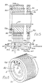
- Figures 5 and 6 show such a compact slipring assembly.
- the assembly comprises a number of sliprings 18 which are spaced apart along the insulating bush 34.
- Each such slipring is made up of three equal conducting segments 18B, each of which is insulated from the others and subtends an angle at its centre of almost 120 degrees. That angle is substantially equal to the angle subtended by the immersed arc of the carrier wheel 3, as indicated in Figure 2 by the intersection of the free surface 'L' of the electrolyte with the periphery of the carrier wheel 3. That arc encompasses the arcs of carrier wheel travel which have been designated 'T' (test) and 'C' (electro-coating treatment).
- Corresponding segments 18B in adjacent sliprings 18 are staggered angularly relative to one another by one pallet pitch, as shown in Figure 6. Hence, the energisation of the respective pallets relative to their respective counter electrodes is timed so as to co-incide with the respective periods during which the associated pallets are travelling submerged in the electro-coating fluid.
- the carrier wheel has two circles of thirty-six pallets; just over one third of them are immersed in the fluid at any given time; each slipring 18 has three conductive segments; and the number of such sliprings for each circle of pallets is twelve.
- the slipring bush 34 is firmly secured on the shaft 4 in a predetermined angular position relative to the carrier wheel such as to achieve the desired electro-coating of each workpiece as it travels through the electro-coating fluid.
- the slipring segments 18B are shown as having connections 18C which pass radially inwards through the insulating bush 34 and then axially so as to protrude from the free end of the slipring assembly as the terminals 18A for receiving the various cables 27.
- a similar slipring arrangement is provided for the other circle of pallets 8B.
- Each of the slipring segments 18B may be sub-divided, if desired, into a short, initial, test portion insulated from a following, longer, electro-coating portion.
- the control unit 33 includes in respect of each brush 17: (a) monitoring means 33M for monitoring the electro-coating current passing through the brush to the associated slipring segment 18B, (b) integrating means 33I for integrating that electric current to provide a measure of the electric charge passed so far in the electro-coating process (and hence the amount of electro-coating material so far deposited on the associated workpiece 29), (c) comparison means 33C for comparing the amount of electric charge with a reference signal derived from a reference signal source 33R, and (d) switching means 33S for terminating the flow of electric current to the brush when the charge so far supplied through it has reached the reference level.
- each pallet and workpiece from its neighbours The benefits arising from electrically isolating each pallet and workpiece from its neighbours are, firstly, it becomes possible to monitor each workpiece for sound electrical contact with its pallet before commencing the electro-coating treatment, and subsequently to reject any workpiece that is not properly located in its pocket. Secondly, it becomes possible to supply power to only such pallets as contain a correctly seated workpiece, thus avoiding treatment of the workpiece supporting surface in the event that a workpiece is absent from, or incorrectly seated in, the pocket. In the case of electro-coating treatments, a pocket not containing a workpiece, or a pocket having an incorrectly seated workpiece, would become electro-coated with an insulating material, thus making it more difficult to treat a workpiece subsequently properly placed in the pocket. Thirdly, it becomes possible to individually monitor and control the electro-coating of each separate workpiece.
- each slipring segment 18B would, in one example, have a non-conductive surface portion extending around approximately two-thirds of its periphery.
- two-thirds of each slipring is usefully occupied by two other similar slipring segments 18B, which feed other pallets 8 that are spaced corresponding distances around the periphery of the carrier wheel 3.
Landscapes
- Chemical & Material Sciences (AREA)
- Engineering & Computer Science (AREA)
- Chemical Kinetics & Catalysis (AREA)
- Electrochemistry (AREA)
- Materials Engineering (AREA)
- Metallurgy (AREA)
- Organic Chemistry (AREA)
- Electroplating Methods And Accessories (AREA)
- Electrolytic Production Of Metals (AREA)
Applications Claiming Priority (2)
| Application Number | Priority Date | Filing Date | Title |
|---|---|---|---|
| GB888811982A GB8811982D0 (en) | 1988-05-20 | 1988-05-20 | Apparatus for electrolytic treatment of articles |
| GB8811982 | 1988-05-20 |
Publications (1)
| Publication Number | Publication Date |
|---|---|
| EP0342837A1 true EP0342837A1 (de) | 1989-11-23 |
Family
ID=10637239
Family Applications (1)
| Application Number | Title | Priority Date | Filing Date |
|---|---|---|---|
| EP89304612A Withdrawn EP0342837A1 (de) | 1988-05-20 | 1989-05-08 | Vorrichtung zur elektrolytischen Behandlung von Artikeln |
Country Status (5)
| Country | Link |
|---|---|
| US (1) | US4909917A (de) |
| EP (1) | EP0342837A1 (de) |
| JP (1) | JPH0219496A (de) |
| GB (2) | GB8811982D0 (de) |
| ZA (1) | ZA893660B (de) |
Families Citing this family (16)
| Publication number | Priority date | Publication date | Assignee | Title |
|---|---|---|---|---|
| US5120410A (en) * | 1990-09-17 | 1992-06-09 | Service Tool Die & Mfg. Company | Rotary electrocoating machine |
| AT2361U1 (de) * | 1997-08-13 | 1998-09-25 | Blau Automobiltechnik Gmbh | Vorrichtung zum galvanisieren von schöpfenden teilen |
| EP1135547B1 (de) | 1998-10-22 | 2003-01-22 | Alcan International Limited | Dekorierte getränkedosenzargen |
| US6792817B2 (en) * | 2002-08-09 | 2004-09-21 | Visteon Global Technologies, Inc. | Fixtures and processes for magnetizing magnetoelastic shafts circumferentially |
| FR2900162B1 (fr) * | 2006-04-21 | 2008-08-01 | Frederic Vacheron | Installation de traitement de surface de pieces metalliques, notamment par electrolyse. |
| EA201500948A1 (ru) | 2013-03-15 | 2016-03-31 | Модьюметл, Инк. | Способ изготовления изделия и изделие, изготовленное вышеуказанным способом |
| WO2014146117A2 (en) | 2013-03-15 | 2014-09-18 | Modumetal, Inc. | A method and apparatus for continuously applying nanolaminate metal coatings |
| BR112017005534A2 (pt) | 2014-09-18 | 2017-12-05 | Modumetal Inc | métodos de preparação de artigos por processos de eletrodeposição e fabricação aditiva |
| EP3194642A4 (de) | 2014-09-18 | 2018-07-04 | Modumetal, Inc. | Verfahren und vorrichtung zum kontinuierlichen auftragen von nanolaminierten metallbeschichtungen |
| CN109922936A (zh) | 2016-09-09 | 2019-06-21 | 莫杜美拓有限公司 | 通过在工件上沉积材料层来制造模具,通过该工艺得到的模具和制品 |
| KR102412452B1 (ko) | 2016-09-14 | 2022-06-23 | 모두메탈, 인크. | 신뢰가능한 고처리량 복합 전기장 발생을 위한 시스템, 및 그로부터 코팅을 제조하는 방법 |
| US12076965B2 (en) | 2016-11-02 | 2024-09-03 | Modumetal, Inc. | Topology optimized high interface packing structures |
| MX2019011073A (es) * | 2017-03-23 | 2019-11-12 | Ykk Corp | Dispositivo de recubrimiento por electrodeposicion. |
| EP3612669A1 (de) * | 2017-04-21 | 2020-02-26 | Modumetal, Inc. | Rohrförmige artikel mit galvanischen beschichtungen und systeme und verfahren zur herstellung derselben |
| WO2019210264A1 (en) | 2018-04-27 | 2019-10-31 | Modumetal, Inc. | Apparatuses, systems, and methods for producing a plurality of articles with nanolaminated coatings using rotation |
| FR3124806A1 (fr) * | 2021-07-02 | 2023-01-06 | Lag2M | Equipment de traitement au défilé de pièces par oxydation micro-arc |
Citations (1)
| Publication number | Priority date | Publication date | Assignee | Title |
|---|---|---|---|---|
| US4659445A (en) * | 1983-02-12 | 1987-04-21 | Herberts Gesellschaft Mit Beschrankter Haftung | Process for coating hollow bodies, which are open on one end |
Family Cites Families (8)
| Publication number | Priority date | Publication date | Assignee | Title |
|---|---|---|---|---|
| US2448117A (en) * | 1942-08-05 | 1948-08-31 | Continental Can Co | Electrolytic can treating machine |
| US3759810A (en) * | 1971-03-29 | 1973-09-18 | American Can Co | Roll through method for electro coating can ends |
| US3849284A (en) * | 1972-09-01 | 1974-11-19 | American Can Co | Apparatus method and valve for electrodepositing a coating on interior surfaces of container bodies |
| GB2085474B (en) * | 1980-10-15 | 1984-10-10 | Metal Box Co Ltd | Electrocoating |
| GB2085922B (en) * | 1980-10-15 | 1984-01-25 | Metal Box Co Ltd | Electrocoating apparatus |
| JPS6021395A (ja) * | 1983-07-15 | 1985-02-02 | Electroplating Eng Of Japan Co | 小径の筒状内面を有するメツキ物のメツキ方法 |
| GB2192899B (en) * | 1986-07-07 | 1991-01-09 | Metal Box Plc | Electro-coating apparatus and method |
| GB2192407B (en) * | 1986-07-07 | 1990-12-19 | Metal Box Plc | Electro-coating apparatus and method |
-
1988
- 1988-05-20 GB GB888811982A patent/GB8811982D0/en active Pending
-
1989
- 1989-05-08 EP EP89304612A patent/EP0342837A1/de not_active Withdrawn
- 1989-05-10 GB GB8910723A patent/GB2219005B/en not_active Expired - Lifetime
- 1989-05-15 US US07/351,635 patent/US4909917A/en not_active Expired - Fee Related
- 1989-05-16 ZA ZA893660A patent/ZA893660B/xx unknown
- 1989-05-20 JP JP1125592A patent/JPH0219496A/ja active Pending
Patent Citations (1)
| Publication number | Priority date | Publication date | Assignee | Title |
|---|---|---|---|---|
| US4659445A (en) * | 1983-02-12 | 1987-04-21 | Herberts Gesellschaft Mit Beschrankter Haftung | Process for coating hollow bodies, which are open on one end |
Also Published As
| Publication number | Publication date |
|---|---|
| ZA893660B (en) | 1990-01-31 |
| GB2219005B (en) | 1992-08-12 |
| JPH0219496A (ja) | 1990-01-23 |
| GB8910723D0 (en) | 1989-06-28 |
| GB8811982D0 (en) | 1988-06-22 |
| US4909917A (en) | 1990-03-20 |
| GB2219005A (en) | 1989-11-29 |
Similar Documents
| Publication | Publication Date | Title |
|---|---|---|
| US4909917A (en) | Electrolytic treatment apparatus | |
| US4800001A (en) | Method and apparatus for continuously galvanizing flat workpieces, and especially printed circuit boards | |
| WO1988000255A1 (en) | Removing a can from a rotating turret | |
| US2506794A (en) | Apparatus for electroplating | |
| HK126596A (en) | Device for the electrolytic treatment of platelike articles | |
| CN101426962A (zh) | 电解涂覆的装置和方法 | |
| US20170335485A1 (en) | Method and apparatus for electrolytically depositing a deposition metal on a workpiece | |
| EP0271089B1 (de) | Verfahren zur Elektroabscheidungsbeschichtung | |
| US3476666A (en) | Centrifugally operating electrodeposition apparatus and method of use | |
| EP0255268B1 (de) | Verfahren zur Elektrotauchlackierung | |
| US4659445A (en) | Process for coating hollow bodies, which are open on one end | |
| US5393395A (en) | Method of surface-treating a half sliding bearing and apparatus for same | |
| US3282819A (en) | Treating of workpieces | |
| US3694336A (en) | Method for can electrodeposition | |
| JP3647508B2 (ja) | メッキ用マガジン | |
| KR0185625B1 (ko) | 알미늄판의 연속 전해에칭, 산화피막 형성방법 및 형성장치 | |
| US3647675A (en) | Automatic rotary electrodeposition apparatus | |
| US2559926A (en) | Anode basket | |
| US20060011479A1 (en) | Method and apparatus for the bulk coating of components | |
| US6926812B2 (en) | Electric feeding method and apparatus for a continuous plating apparatus | |
| GB2104025A (en) | Improvements in or relating to electro-plating machines | |
| US6090262A (en) | Barrel plating method | |
| Harrison et al. | Electrical Energisation of Workpieces in Electrolytic Treatment Apparatus | |
| US4659446A (en) | Apparatus for electroplating printing cylinders | |
| US4946571A (en) | Electrode |
Legal Events
| Date | Code | Title | Description |
|---|---|---|---|
| PUAI | Public reference made under article 153(3) epc to a published international application that has entered the european phase |
Free format text: ORIGINAL CODE: 0009012 |
|
| 17P | Request for examination filed |
Effective date: 19890516 |
|
| AK | Designated contracting states |
Kind code of ref document: A1 Designated state(s): AT BE CH DE ES FR GB GR IT LI LU NL SE |
|
| RAP1 | Party data changed (applicant data changed or rights of an application transferred) |
Owner name: CMB PACKAGING (UK) LIMITED |
|
| RAP1 | Party data changed (applicant data changed or rights of an application transferred) |
Owner name: CMB FOODCAN PLC |
|
| 17Q | First examination report despatched |
Effective date: 19911219 |
|
| RAP1 | Party data changed (applicant data changed or rights of an application transferred) |
Owner name: CARNAUDMETALBOX PLC |
|
| STAA | Information on the status of an ep patent application or granted ep patent |
Free format text: STATUS: THE APPLICATION IS DEEMED TO BE WITHDRAWN |
|
| 18D | Application deemed to be withdrawn |
Effective date: 19930609 |