EP0342789B1 - Verfahren zum Abschätzen der Referenzgeschwindigkeit und der Referenzbeschleunigung bei einer Antriebssteuerung und einer Gleitschutzbremssteuerung - Google Patents
Verfahren zum Abschätzen der Referenzgeschwindigkeit und der Referenzbeschleunigung bei einer Antriebssteuerung und einer Gleitschutzbremssteuerung Download PDFInfo
- Publication number
- EP0342789B1 EP0342789B1 EP89303560A EP89303560A EP0342789B1 EP 0342789 B1 EP0342789 B1 EP 0342789B1 EP 89303560 A EP89303560 A EP 89303560A EP 89303560 A EP89303560 A EP 89303560A EP 0342789 B1 EP0342789 B1 EP 0342789B1
- Authority
- EP
- European Patent Office
- Prior art keywords
- ref
- acceleration
- wheel
- current
- speed
- Prior art date
- Legal status (The legal status is an assumption and is not a legal conclusion. Google has not performed a legal analysis and makes no representation as to the accuracy of the status listed.)
- Expired - Lifetime
Links
- 230000001133 acceleration Effects 0.000 title claims description 58
- 238000000034 method Methods 0.000 title claims description 28
- 230000003044 adaptive effect Effects 0.000 claims description 7
- 230000005484 gravity Effects 0.000 claims description 2
- 230000001419 dependent effect Effects 0.000 claims 1
- 239000012530 fluid Substances 0.000 description 7
- 238000013459 approach Methods 0.000 description 4
- 238000012935 Averaging Methods 0.000 description 3
- 230000008878 coupling Effects 0.000 description 3
- 238000010168 coupling process Methods 0.000 description 3
- 238000005859 coupling reaction Methods 0.000 description 3
- 230000000694 effects Effects 0.000 description 3
- 238000010586 diagram Methods 0.000 description 2
- 238000004364 calculation method Methods 0.000 description 1
- 230000008859 change Effects 0.000 description 1
- 238000012937 correction Methods 0.000 description 1
- 230000003247 decreasing effect Effects 0.000 description 1
- 230000003993 interaction Effects 0.000 description 1
- 230000008569 process Effects 0.000 description 1
- 238000012545 processing Methods 0.000 description 1
Images


Classifications
-
- B—PERFORMING OPERATIONS; TRANSPORTING
- B60—VEHICLES IN GENERAL
- B60T—VEHICLE BRAKE CONTROL SYSTEMS OR PARTS THEREOF; BRAKE CONTROL SYSTEMS OR PARTS THEREOF, IN GENERAL; ARRANGEMENT OF BRAKING ELEMENTS ON VEHICLES IN GENERAL; PORTABLE DEVICES FOR PREVENTING UNWANTED MOVEMENT OF VEHICLES; VEHICLE MODIFICATIONS TO FACILITATE COOLING OF BRAKES
- B60T8/00—Arrangements for adjusting wheel-braking force to meet varying vehicular or ground-surface conditions, e.g. limiting or varying distribution of braking force
- B60T8/17—Using electrical or electronic regulation means to control braking
- B60T8/176—Brake regulation specially adapted to prevent excessive wheel slip during vehicle deceleration, e.g. ABS
- B60T8/1761—Brake regulation specially adapted to prevent excessive wheel slip during vehicle deceleration, e.g. ABS responsive to wheel or brake dynamics, e.g. wheel slip, wheel acceleration or rate of change of brake fluid pressure
- B60T8/17616—Microprocessor-based systems
-
- B—PERFORMING OPERATIONS; TRANSPORTING
- B60—VEHICLES IN GENERAL
- B60T—VEHICLE BRAKE CONTROL SYSTEMS OR PARTS THEREOF; BRAKE CONTROL SYSTEMS OR PARTS THEREOF, IN GENERAL; ARRANGEMENT OF BRAKING ELEMENTS ON VEHICLES IN GENERAL; PORTABLE DEVICES FOR PREVENTING UNWANTED MOVEMENT OF VEHICLES; VEHICLE MODIFICATIONS TO FACILITATE COOLING OF BRAKES
- B60T8/00—Arrangements for adjusting wheel-braking force to meet varying vehicular or ground-surface conditions, e.g. limiting or varying distribution of braking force
- B60T8/17—Using electrical or electronic regulation means to control braking
- B60T8/171—Detecting parameters used in the regulation; Measuring values used in the regulation
-
- B—PERFORMING OPERATIONS; TRANSPORTING
- B60—VEHICLES IN GENERAL
- B60T—VEHICLE BRAKE CONTROL SYSTEMS OR PARTS THEREOF; BRAKE CONTROL SYSTEMS OR PARTS THEREOF, IN GENERAL; ARRANGEMENT OF BRAKING ELEMENTS ON VEHICLES IN GENERAL; PORTABLE DEVICES FOR PREVENTING UNWANTED MOVEMENT OF VEHICLES; VEHICLE MODIFICATIONS TO FACILITATE COOLING OF BRAKES
- B60T8/00—Arrangements for adjusting wheel-braking force to meet varying vehicular or ground-surface conditions, e.g. limiting or varying distribution of braking force
- B60T8/17—Using electrical or electronic regulation means to control braking
- B60T8/175—Brake regulation specially adapted to prevent excessive wheel spin during vehicle acceleration, e.g. for traction control
-
- B—PERFORMING OPERATIONS; TRANSPORTING
- B60—VEHICLES IN GENERAL
- B60T—VEHICLE BRAKE CONTROL SYSTEMS OR PARTS THEREOF; BRAKE CONTROL SYSTEMS OR PARTS THEREOF, IN GENERAL; ARRANGEMENT OF BRAKING ELEMENTS ON VEHICLES IN GENERAL; PORTABLE DEVICES FOR PREVENTING UNWANTED MOVEMENT OF VEHICLES; VEHICLE MODIFICATIONS TO FACILITATE COOLING OF BRAKES
- B60T8/00—Arrangements for adjusting wheel-braking force to meet varying vehicular or ground-surface conditions, e.g. limiting or varying distribution of braking force
- B60T8/17—Using electrical or electronic regulation means to control braking
- B60T8/176—Brake regulation specially adapted to prevent excessive wheel slip during vehicle deceleration, e.g. ABS
- B60T8/1769—Brake regulation specially adapted to prevent excessive wheel slip during vehicle deceleration, e.g. ABS specially adapted for vehicles having more than one driven axle, e.g. four-wheel drive vehicles
-
- B—PERFORMING OPERATIONS; TRANSPORTING
- B60—VEHICLES IN GENERAL
- B60T—VEHICLE BRAKE CONTROL SYSTEMS OR PARTS THEREOF; BRAKE CONTROL SYSTEMS OR PARTS THEREOF, IN GENERAL; ARRANGEMENT OF BRAKING ELEMENTS ON VEHICLES IN GENERAL; PORTABLE DEVICES FOR PREVENTING UNWANTED MOVEMENT OF VEHICLES; VEHICLE MODIFICATIONS TO FACILITATE COOLING OF BRAKES
- B60T2250/00—Monitoring, detecting, estimating vehicle conditions
- B60T2250/04—Vehicle reference speed; Vehicle body speed
- B60T2250/042—Reference speed calculation in ASR or under wheel spinning condition
Definitions
- the invention relates generally to traction and anti-skid braking vehicle wheel control systems. More specifically, the invention concerns a method for obtaining an estimate of vehicle reference speed and acceleration suitable for use in determining wheel slip in such systems.
- Known anti-skid braking control systems use various mathematical manipulations to estimate the speed of a vehicle for comparison with the rotational speed of a given vehicle wheel to calculate wheel "slip" for that wheel, wheel slip being a parameter needed in order to make decisions concerning wheel lock control.
- a method for estimating a vehicle reference speed and reference acceleration suitable for determining relative wheel slip of an individual wheel of the vehicle includes the steps of periodically determining extrapolated values of reference speed and reference acceleration from previously updated values thereof, estimating the current wheel slip from the extrapolated reference speed, computing adaptive filter gains which are functions of the current estimate of wheel slip and the current estimate of wheel acceleration, generating an error signal as a function of the difference between a current wheel speed and the extrapolated value of the reference speed, and generating updated values of reference speed and reference acceleration by adding to the extrapolated values of reference speed and acceleration a product of the computed filter gains and the error signal.
- the method does not require averaging or comparison with other wheel speeds to obtain an estimate of the wheel slip appropriate to a single wheel.
- braking may be improved through its use, since it is not necessary to maintain low slip values on some wheels in order to obtain a suitable reference speed estimate.
- FIG. 1 depicts a perspective view of an automotive vehicle and shows the typical location of major components of an anti-lock brake system.
- Vehicle 100 includes a hydraulic unit 110 which feeds brakes at the four wheels of the vehicle via brake fluid lines 160.
- the hydraulic unit 110 is controlled via an electronic controller 120 which utilises wheel speed sensor data from wheel speed sensors such as 150 coupled via electrical busses 170 to the electronic controller 120.
- the electronic controller 120 utilises wheel speed and acceleration data to estimate wheel slip. This estimated data is then utilised by an anti-lock algorithm to issue various commands to the hydraulic unit 110 for modulatng brake pressure to the individual vehicle wheels.
- a proportioning valve 140 is shown in the hydraulic feed to the rear wheels.
- this proportioning valve may not be necessary, since the speed estimates derived through use of the invention do not require that the rear wheels be maintained at a relatively low value of slip during the braking process as with the prior art.
- Relays 130 are used to relay electronic control signals from electronic controller 120 to the various other systems such as hydraulic unit 110.
- FIG. 2 The functional block diagram of Figure 2 sets forth in more detail the functional elements of a typical anti-lock brake system and is used to explain where the adaptive filters used to implement a part of the method of the present invention would be located with respect to the overall vehicular control system.
- wheel speed sensors 150-1, 150-2, 150-3 and 150-4 monitor respectively the rotational speeds of wheel 210-1, 210-2, 210-3 and 210-4.
- This wheel speed data is coupled via busses 170-1 through 170-4 to sensor processing circuitry 220 which converts the signals to an appropriate level for coupling via bus 170-6 to electronic controller 120.
- Electronic controller 120 is powered basically by battery 224 over bus 170-7.
- scanpoints which feed failure switches 222 whose outputs are coupled via bus 170-5 to electronic controller 120.
- Electronic controller 120 includes routines for estimating wheel speed, wheel acceleration, tyre slip, and vehicle speed.
- the various data estimates are utilised by an algorithm resident in electronic controller 120 to implement various brake control commands via brake control logic 120-1.
- the routines for the data estimation and fault protection are shown in functional block dashed form in electronic controller 120 as tyre slip estimation routine 120-2, wheel acceleration estimation routine 120-3, wheel speed estimation routine 120-4, vehicle speed estimation routine 120-5 and fault protection 120-6.
- brake control logic 120-1 issues various brake pressure modulation control signals via bus 170-9 to solenoid drivers 250.
- the solenoid drive control signals are coupled via bus 170-10 to electro-hydraulic solenoids such as 240, 242, and 244 which are placed in the brake fluid lines 160 feeding the various brake calipers associated with the vehicle wheels to modulate the brake pressure applied thereto.
- the controller algorithm in use also utilises information concerning the states of the various brakes from a brake switch 230, the information being coupled to the electronic controller 120 via bus 170-8.
- Brake switch 230 is coupled to a driver 232 which in turn is coupled to a master cylinder 234, then to a servomaster 236 then via brake fluid lines 160-5 to the electro-hydraulic solenoids 240-244.
- An electro-hydraulic pump 239 is coupled to a conventional accumulator 238 which is, in turn, coupled by brake fluid lines 160-4 to servomaster 236 and to the electro-hydraulic solenoids 240, 242, and 244.
- Electro-hydraulic solenoid 240 is coupled between the servomaster 236 and brake calipers 260-3 and 260-4 for the rear wheels 210-3, 210-4 via brake fluid lines 160-5 and 160-3. Electro-hydraulic solenoids 242 and 244 are likewise respectively coupled to brake calipers 260-1 and 260-2 which are associated with the front wheels 210-1, 210-2 of the vehicle. The coupling between the electro-hydraulic solenoids 242, 244 and the front brake calipers 260-1, 260-2 is via brake fluid lines 160-1 and 160-2, while the coupling from electro-hydraulic solenoid 240 passes via brake fluid line 160-3 to both brake calipers 260-3 and 260-4 for the rear wheels 210-3, 210-4.
- the present invention pertains to a method for generating the gain values for adaptive filters used in estimating the vehicle reference speed and reference acceleration through use of the appropriate routines resident in (microcomputer-based) electronic controller 120 of Figures 1 or 2.
- the speed and acceleration estimates are used, in turn, for calculating slip at individual vehicle wheels for use by the anti-skid braking or traction control algorithms.
- Figures 3 and 4 show plots of wheel speed versus time for a typical anti-skid brake system and a traction control system, respectively.
- the objective is to find a smooth curve which interpolates between periods of high wheel acceleration, the smooth curve being shown in Figures 3 and 4 as dashed curves 304 and 404, respectively.
- the interpolation is to be performed using only current wheel speed and acceleration data to, in effect, form a smooth envelope embracing the peaks 308 of curve 302 of Figure 3 and the valleys 406 of curve 402 of Figure 4.
- the estimates of the instantaneous wheel speed and acceleration are available using a conventional software implemented linear filter, for example, operating on wheel speed sensor data.
- the estimated reference speed and acceleration are computed at intervals which depend upon the speed of the (microprocessor-based) electronic controller 120 of Figures 1 and 2, but in any case, less frequently than the wheel speed calculations.
- a typical update interval for reference speed and acceleration computation is 10 msec.
- the following illustrative procedure could be used.
- the reference speed and acceleration are set to zero.
- wheel slip s i suitable for traction control as well as anti-skid braking is given in accordance with the following.
- a typical range for s0 is about 0.08 to about 0.12, while a typical range for a0 is from about 1.0g to about 1.4g, where g is the acceleration of gravity.
- Suitable filter performance means that one may be able to smoothly extrapolate between the speed peaks 308 in Figure 3 or valleys 406 in Figure 4.
Landscapes
- Engineering & Computer Science (AREA)
- Transportation (AREA)
- Mechanical Engineering (AREA)
- Microelectronics & Electronic Packaging (AREA)
- Physics & Mathematics (AREA)
- Fluid Mechanics (AREA)
- Chemical & Material Sciences (AREA)
- Combustion & Propulsion (AREA)
- Regulating Braking Force (AREA)
Claims (14)
- Ein Verfahren zum Abschätzen einer Fahrzeug-Referenzgeschwindigkeit und -Referenzbeschleunigung, die zum Bestimmen eines relativen Radschlupfes von einem einzelnen Rad des Fahrzeuges geeignet sind, gekennzeichnet durch die Schritte, daß periodisch extrapolierte Werte (v' ref , a' ref ) der Referenzgeschwindigkeit und Referenzbeschleunigung aus deren vorher aktualisierten Werten (v ref , a ref ) bestimmt werden; ein aktueller Radschlupf (s i ) des einzelnen Rades aus dem extrapolierten Wert der Referenzgeschwindigkeit abgeschätzt wird; erste und zweite adaptive Filtergewinne (K v , K a ) berechnet werden, die Funktionen einer aktuellen Abschätzung des Radschlupfes und einer aktuellen Abschätzung der Radbeschleunigung (a i ) sind; ein Fehlersignal [(s i , a i ) × e i ] als eine Funktion einer Differenz (e i ) zwischen der aktuellen Radgeschwindigkeit und dem extrapolierten Wert der Referenzgeschwindigkeit erzeugt wird; und aktualisierte Werte der Referenzgeschwindigkeit und Referenzbeschleunigung erzeugt werden, indem ein Produkt des ersten Gewinnes und des Fehlersignals zu dem extrapolierten Wert der Referenzgeschwindigkeit addiert wird und indem ein Produkt des zweiten Gewinnes und des Fehlersignals zu dem extrapolierten Wert der Referenzbeschleunigung addiert wird.
- Ein Verfahren nach Anspruch 1, worin die ersten und zweiten Filtergewinne relativ klein sind, wann immer die aktuellen Abschätzungen des Schlupfes und der Radbeschleunigung außerhalb jeweiliger, vorher bestimmter Bereiche liegen, und relativ groß sind, wann immer die aktuellen Abschätzungen des Schlupfes und der Radbeschleunigung innerhalb der jeweiligen, vorher bestimmten Bereiche liegen.
- Ein Verfahren nach Anspruch 2, worin der extrapolierte Wert der Referenzgeschwindigkeit gleich dem vorher aktualisierten Wert der Referenzgeschwindigkeit plus dem Produkt des vorher aktualisierten Wertes der Referenzbeschleunigung und einer vorher ausgewählten Aktualisierungzeitspanne ist.
- Ein Verfahren nach Anspruch 3, worin der extrapolierte Wert der Referenzbeschleunigung gleich dem vorher aktualisierten Wert der Referenzbeschleunigung ist.
- Ein Verfahren nach irgendeinem der Ansprüche 2 bis 4, worin der erste und/oder zweite Gewinnfaktor eine Summe aus einer ersten, vorher ausgewählten Konstanten und einem Produkt einer ersten Funktion des aktuellen abgeschätzten Radschlupfes und einer zweiten Funktion der aktuellen Radbeschleunigung aufweist.
- Ein Verfahren nach Anspruch 5, worin die erste Funktion proportional zu (1 - s i /s₀) ist, wenn s i kleiner als s₀ ist, und gleich Null andernfalls ist, wo s i der aktuelle abgeschätzte Radschlupf ist und s₀ ein vorher ausgewählter positiver konstanter Referenzschlupfwert ist; und worin die zweite Funktion proportional zu


- Ein Verfahren nach irgendeinem der Ansprüche 1 bis 6, worin der aktuelle abgeschätzte Radschlupf so definiert ist, daß er sowohl für eine Antriebs- als auch eine Anti-Blockier-Spurregelung verwendet werden kann.
- Ein Verfahren nach Anspruch 7, worin der aktuelle abgeschätzte Radschlupf s i aus einem Beschleunigungsvorzeichenwert SIGN, der aktuellen Radgeschwindigkeit v i , dem extrapolierten Wert der Referenzgeschwindigkeit v' ref und dem extrapolierten Wert der Referenzbeschleunigung a' ref bestimmt wird gemäß


- Ein Verfahren zum Abschätzen einer Fahrzeug-Referenzgeschwindigkeit und -Referenzbeschleunigung, die zum Bestimmen des Radschlupfes eines einzelnen Rades des Fahrzeuges geeignet sind, gekennzeichnet durch die Schritte, daßa) anfangs die aktualisierte Referenzgeschwindigkeit v ref und die aktualisierte Referenzbeschleunigung a ref auf Null gesetzt werden;b) für ein vorher ausgewähltes Aktualisierungszeitintervall dt gewartet wird;c) extrapolierte Werte der Referenzgeschwindigkeit v' ref und Referenzbeschleunigung a' ref derart erzeugt werden, daß


d) eine Differenz e i zwischen einer aktuellen Radgeschwindigkeit v i und v' ref oder
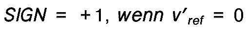
 e) eine Vorzeichenfunktion SIGN gemäß dem folgenden bestimmt wird


f) ein aktueller Wert des Radschlupfes s i gemäß dem folgenden berechnet wird


g) eine relative Radbeschleunigung da i durch h) ein positiver konstanter Referenzschlupfwert s₀ und ein positiver konstanter Referenzbeschleunigungswert a₀ ausgewählt werden;i) zwei Hilfsfunktionen f₁ und f₂ gemäß dem folgenden berechnet werden


j) zwei adaptive Filtergewinne K v und K a gemäß dem folgenden berechnet werden und
und Konstanten sind, die ausgewählt werden, um eine gewünschte Filterfunktion zu erhalten;
 k) neue aktualisierte Werte der Referenzgeschwindigkeit v ref und Referenzbeschleunigung a ref gemäß dem folgenden berechnet werden
 l) zu Schritt b) zurückgekehrt wird.
 - Ein Verfahren nach Anspruch 9, worin typische Werte für s₀ in dem Bereich von etwa 0,08 bis etwa 0,12 liegen.
- Ein Verfahren nach Anspruch 9 oder Anspruch 10, worin typische Werte für a₀ in dem Bereich von etwa 1,0g bis etwa 1,4g liegen, wo g die Gravitationsbeschleunigung ist.
- Ein Verfahren nach irgendeinem der Ansprüche 9 bis 11, worin typische Werte fürund
 in dem Bereich von etwa 0,01 bis etwa 0,07 liegen.
- Ein Verfahren nach irgendeinem der Ansprüche 9 bis 12, worin typische Werte fürund
 in dem Bereich von etwa 0,2 bis etwa 0,4 liegen.
- Ein Verfahren gemäß Anspruch 9, worin a₀ und s₀ aus einer Vielzahl von Werten ausgewählt werden, die von einer aktuellen Abschätzung der Fahrzeug-Referenzgeschwindigkeit abhängen.
Applications Claiming Priority (2)
| Application Number | Priority Date | Filing Date | Title |
|---|---|---|---|
| US194362 | 1988-05-16 | ||
| US07/194,362 US4818037A (en) | 1988-05-16 | 1988-05-16 | Method for estimating reference speed and acceleration for traction and anti-skid braking control |
Publications (3)
| Publication Number | Publication Date |
|---|---|
| EP0342789A2 EP0342789A2 (de) | 1989-11-23 |
| EP0342789A3 EP0342789A3 (de) | 1991-01-30 |
| EP0342789B1 true EP0342789B1 (de) | 1993-08-04 |
Family
ID=22717293
Family Applications (1)
| Application Number | Title | Priority Date | Filing Date |
|---|---|---|---|
| EP89303560A Expired - Lifetime EP0342789B1 (de) | 1988-05-16 | 1989-04-11 | Verfahren zum Abschätzen der Referenzgeschwindigkeit und der Referenzbeschleunigung bei einer Antriebssteuerung und einer Gleitschutzbremssteuerung |
Country Status (3)
| Country | Link |
|---|---|
| US (1) | US4818037A (de) |
| EP (1) | EP0342789B1 (de) |
| DE (1) | DE68908007T2 (de) |
Families Citing this family (39)
| Publication number | Priority date | Publication date | Assignee | Title |
|---|---|---|---|---|
| US5233529A (en) * | 1987-02-28 | 1993-08-03 | Robert Bosch Gmbh | Automatic anti-skid brake control system |
| JP2646572B2 (ja) * | 1987-09-04 | 1997-08-27 | 日産自動車株式会社 | アンチスキッド制御装置の擬似車速発生装置 |
| JP2783799B2 (ja) * | 1987-09-04 | 1998-08-06 | 日産自動車株式会社 | アンチスキッド制御装置の擬似車速発生装置 |
| JP2731149B2 (ja) * | 1987-09-04 | 1998-03-25 | 日産自動車株式会社 | アンスキッド制御装置の擬似車速発生装置 |
| US5132907A (en) * | 1987-10-12 | 1992-07-21 | Nissan Motor Company, Limited | Control system for controlling wheel slippage with projection of vehicle speed representative data |
| DE3806213A1 (de) * | 1988-02-26 | 1989-09-07 | Lucas Ind Plc | Verfahren zum regeln des bremsdruckes |
| JP2977037B2 (ja) * | 1988-02-29 | 1999-11-10 | 日産自動車株式会社 | アンチスキッド制御装置 |
| US5255193A (en) * | 1988-05-12 | 1993-10-19 | Nissan Motor Company | Traction control system for controlling engine output and brake for maintaining optimum wheel traction with road friction level dependent brake control |
| GB8814931D0 (en) * | 1988-06-23 | 1988-07-27 | Lucas Ind Plc | Vehicle speed estimation in anti-lock braking systems |
| JP2688948B2 (ja) * | 1988-10-26 | 1997-12-10 | 株式会社曙ブレーキ中央技術研究所 | 車両のアンチロック制御方法 |
| US5117361A (en) * | 1988-11-17 | 1992-05-26 | Toshio Takayama | Anti-skid brake control apparatus |
| JPH02141355A (ja) * | 1988-11-22 | 1990-05-30 | Sumitomo Electric Ind Ltd | アンチロック制御装置 |
| DE3841956A1 (de) * | 1988-12-14 | 1990-06-21 | Bosch Gmbh Robert | Antiblockierregelsystem |
| US4916619A (en) * | 1989-04-13 | 1990-04-10 | General Motors Corporation | Adaptive wheel slip threshold |
| DE3915879C5 (de) * | 1989-05-16 | 2005-07-14 | Continental Teves Ag & Co. Ohg | Verfahren und Schaltungsanordnung zur Auswertung der Radgeschwindigkeitssignale für eine Blockierschutz- oder Antriebsschlupfregelung |
| JP2741415B2 (ja) * | 1989-11-10 | 1998-04-15 | 本田技研工業株式会社 | 四輪操舵車両のトラクション制御装置 |
| US5043896A (en) * | 1990-06-11 | 1991-08-27 | Ford Motor Company | Vehicle braking system controller/road friction and hill slope tracking system |
| DE4024815A1 (de) * | 1990-08-04 | 1992-02-13 | Bosch Gmbh Robert | Verfahren zur schaetzung der geschwindigkeit |
| JP2796039B2 (ja) * | 1993-05-14 | 1998-09-10 | 株式会社日立製作所 | 電気自動車の制動装置 |
| US5388895A (en) * | 1993-07-30 | 1995-02-14 | Kelsey-Hayes Company | Method and system for detecting and correcting vehicle speed reference signals in anti-lock brake systems |
| US5424962A (en) * | 1993-12-29 | 1995-06-13 | Comsat | Method and system for projecting steady state conditions of a product from transient monotonic or cyclic data |
| DE19503271A1 (de) * | 1995-02-02 | 1996-08-08 | Bosch Gmbh Robert | Antiblockierregelsystem |
| DE19534566C2 (de) * | 1995-09-18 | 1999-02-11 | Hella Kg Hueck & Co | Verfahren zur Filterung eines Geschwindigkeitssignals für Kraftfahrzeuganwendungen |
| US5764137A (en) * | 1996-12-09 | 1998-06-09 | Chrysler Corporation | System and method for diagnosing loss of pressure in tires of a vehicle |
| DE19713251A1 (de) | 1997-03-29 | 1998-10-01 | Bosch Gmbh Robert | Verfahren und Vorrichtung zur Ermittlung einer die Fahrzeuggeschwindigkeit beschreibenden Größe |
| DE19747093C2 (de) * | 1997-10-24 | 2002-10-17 | Siemens Ag | Elektrisch betätigte Bremsanlage |
| DE19805091C2 (de) * | 1998-02-09 | 2002-10-17 | Siemens Ag | Verfahren zum Ermitteln der Verzögerung eines Kraftfahrzeuges und Bremsanlage, die dieses Verfahren verwendet |
| DE10254628A1 (de) | 2002-11-22 | 2004-06-03 | Volkswagen Ag | Verfahren zur Ermittlung einer Fahrzeug-Referenzgeschwindigkeit |
| US6882920B2 (en) * | 2003-04-29 | 2005-04-19 | Goodrich Corporation | Brake control system |
| US7121374B1 (en) * | 2005-04-30 | 2006-10-17 | Cnh America Llc | Four-wheel drive combine with slip control |
| KR101129257B1 (ko) * | 2008-01-16 | 2012-03-26 | 주식회사 만도 | 자동차 차체 전자제어 시스템의 추정 기준 차체 속도결정방법 |
| CN103144621B (zh) | 2009-01-08 | 2015-05-27 | 株式会社小松制作所 | 牵引控制装置 |
| JP5020388B2 (ja) * | 2009-01-08 | 2012-09-05 | 株式会社小松製作所 | 車両速度推定装置及びトラクションコントロール装置 |
| US9555783B2 (en) | 2011-03-03 | 2017-01-31 | Robert Bosch Gmbh | Wheel speed estimation using a drivetrain model |
| US9463873B2 (en) * | 2014-07-13 | 2016-10-11 | The Boeing Company | Vehicle braking system having braking control and skid reduction functions |
| ITUB20159358A1 (it) * | 2015-12-22 | 2017-06-22 | Faiveley Transport Italia Spa | Procedimento per il controllo e il recupero dell'aderenza delle ruote di un assile controllato di un veicolo ferroviario. |
| DE102016122245A1 (de) * | 2016-11-18 | 2018-05-24 | Dr. Ing. H.C. F. Porsche Aktiengesellschaft | Verfahren und Vorrichtung zur Traktionskontrolle für ein Fahrzeug |
| CN109307782B (zh) * | 2017-07-28 | 2020-10-27 | 华创车电技术中心股份有限公司 | 车速估算装置、车速估算方法、及计算器可读介质 |
| US11091135B2 (en) * | 2018-06-07 | 2021-08-17 | Mando Corporation | Electronic control apparatus and method of controlling the same |
Family Cites Families (15)
| Publication number | Priority date | Publication date | Assignee | Title |
|---|---|---|---|---|
| SE332570B (de) * | 1968-10-22 | 1971-02-08 | O Kullberg | |
| US3985396A (en) * | 1972-07-20 | 1976-10-12 | Aisin Seiki Kabushiki Kaisha | Method, circuit, and apparatus for anti-skid brake control in motor vehicles |
| US3934938A (en) * | 1972-07-20 | 1976-01-27 | Aisin Seiki Kabushiki Kaisha | Method, circuit, and apparatus for anti-skid brake control in motor vehicles |
| US3857613A (en) * | 1972-09-29 | 1974-12-31 | Nippon Air Brake Co | Electronic controller for use in anti-skid system for vehicles |
| US3953080A (en) * | 1973-11-28 | 1976-04-27 | General Motors Corporation | Adaptive anti-lock brake control system |
| US3964796A (en) * | 1975-03-27 | 1976-06-22 | General Motors Corporation | Adaptive anti-lock brake control apparatus |
| US4076332A (en) * | 1977-01-24 | 1978-02-28 | General Motors Corporation | Wheel lock control circuit |
| JPS5653944A (en) * | 1979-10-09 | 1981-05-13 | Nissan Motor Co Ltd | Antiskid controller |
| DE3152999C2 (de) * | 1980-08-25 | 1991-04-18 | Honda Giken Kogyo K.K., Tokio/Tokyo, Jp | |
| JPS596163A (ja) * | 1982-07-02 | 1984-01-13 | Honda Motor Co Ltd | アンチロツク制動装置 |
| JPS6035647A (ja) * | 1983-08-09 | 1985-02-23 | Nippon Denso Co Ltd | アンチスキツド制御装置 |
| US4715662A (en) * | 1983-12-16 | 1987-12-29 | Robert Bosch Gmbh | Method for determining an optimal slip value |
| DE3345730C2 (de) * | 1983-12-17 | 1994-06-23 | Teves Gmbh Alfred | Anordnung zur Erzeugung einer Fahrzeugreferenzgeschwindigkeit |
| US4656588A (en) * | 1984-04-17 | 1987-04-07 | Nissan Motor Company, Limited | Anti-skid brake control system with a plurality of independently operative digital controllers |
| EP0176785B1 (de) * | 1984-09-28 | 1992-12-02 | Toyota Jidosha Kabushiki Kaisha | Radschlupfregelsystem |
-
1988
- 1988-05-16 US US07/194,362 patent/US4818037A/en not_active Expired - Lifetime
-
1989
- 1989-04-11 DE DE89303560T patent/DE68908007T2/de not_active Expired - Lifetime
- 1989-04-11 EP EP89303560A patent/EP0342789B1/de not_active Expired - Lifetime
Also Published As
| Publication number | Publication date |
|---|---|
| US4818037A (en) | 1989-04-04 |
| EP0342789A2 (de) | 1989-11-23 |
| EP0342789A3 (de) | 1991-01-30 |
| DE68908007T2 (de) | 1993-12-02 |
| DE68908007D1 (de) | 1993-09-09 |
Similar Documents
| Publication | Publication Date | Title |
|---|---|---|
| EP0342789B1 (de) | Verfahren zum Abschätzen der Referenzgeschwindigkeit und der Referenzbeschleunigung bei einer Antriebssteuerung und einer Gleitschutzbremssteuerung | |
| EP1317363B1 (de) | Schlechtwegerkennung mit verwendung von daten des radaufhängungssystems | |
| EP0495242B1 (de) | Lastzüge-Bremssteuersystem | |
| US5388896A (en) | Method for braking motor vehicle wheels while reducing a yawing moment of an antilock braking system | |
| EP0261783B1 (de) | Sich anpassender Antiblockierbremsregler | |
| US7114787B2 (en) | Braking system for trailers of utility vehicles | |
| EP0497392B1 (de) | Berechnung der Referenzgeschwindigkeit in Blockierschutzbremssystemen | |
| EP0982206B1 (de) | Verfahren zur Schätzung der Fahrzeuggiergeschwindigkeit | |
| EP0796185B1 (de) | Verfahren zur Berechnung der Radreferenzgeschwindigkeit bei einer Antiblockierbremssystem | |
| US6859712B2 (en) | Adaptive compensation method for an anti-lock brake control | |
| US6618660B2 (en) | Anti-lock brake yaw control method | |
| EP0788955A3 (de) | Steuerverfahren für Antiblockier-Bremssysteme mit Dehnungssensor und Messeinrichtung für Radbetätigungskraft | |
| US6079801A (en) | Method for electrically actuated braking of a motor vehicle and electrically actuated brake system | |
| US6490518B1 (en) | Anti-lock brake control method having adaptive exit criteria | |
| JP2792975B2 (ja) | ロツク防止制御装置 | |
| US5102202A (en) | Method for calculating a value indicative of dynamic turning radius of curvature | |
| US6588859B2 (en) | System and method for vehicle stability enhancement control with surface estimate | |
| EP0428777B1 (de) | Blockierschutz-Bremssteuervorrichtung | |
| US5686662A (en) | Brake control system | |
| US5941924A (en) | Method and device for controlling a vehicle braking system | |
| EP0992411B1 (de) | Schätzung der Fahrzeuggeschwindigkeit für Regulierung der ABS-Funktion | |
| CA1252181A (en) | Antiskid control system responsive to road surface reaction | |
| US6272419B1 (en) | Method for controlling vehicle behavior during cornering and a braking system for implementation thereof | |
| US20040002804A1 (en) | Method for determining optimal abs slip and deceleration thresholds | |
| US6553304B2 (en) | Anti-lock brake control method having adaptive initial brake pressure reduction |
Legal Events
| Date | Code | Title | Description |
|---|---|---|---|
| PUAI | Public reference made under article 153(3) epc to a published international application that has entered the european phase |
Free format text: ORIGINAL CODE: 0009012 |
|
| AK | Designated contracting states |
Kind code of ref document: A2 Designated state(s): DE FR GB |
|
| PUAL | Search report despatched |
Free format text: ORIGINAL CODE: 0009013 |
|
| AK | Designated contracting states |
Kind code of ref document: A3 Designated state(s): DE FR GB |
|
| RHK1 | Main classification (correction) |
Ipc: B60T 8/32 |
|
| 17P | Request for examination filed |
Effective date: 19910320 |
|
| 17Q | First examination report despatched |
Effective date: 19920429 |
|
| GRAA | (expected) grant |
Free format text: ORIGINAL CODE: 0009210 |
|
| AK | Designated contracting states |
Kind code of ref document: B1 Designated state(s): DE FR GB |
|
| REF | Corresponds to: |
Ref document number: 68908007 Country of ref document: DE Date of ref document: 19930909 |
|
| ET | Fr: translation filed | ||
| PLBE | No opposition filed within time limit |
Free format text: ORIGINAL CODE: 0009261 |
|
| STAA | Information on the status of an ep patent application or granted ep patent |
Free format text: STATUS: NO OPPOSITION FILED WITHIN TIME LIMIT |
|
| 26N | No opposition filed | ||
| REG | Reference to a national code |
Ref country code: GB Ref legal event code: IF02 |
|
| PGFP | Annual fee paid to national office [announced via postgrant information from national office to epo] |
Ref country code: DE Payment date: 20080602 Year of fee payment: 20 |
|
| PGFP | Annual fee paid to national office [announced via postgrant information from national office to epo] |
Ref country code: FR Payment date: 20080417 Year of fee payment: 20 |
|
| PGFP | Annual fee paid to national office [announced via postgrant information from national office to epo] |
Ref country code: GB Payment date: 20080429 Year of fee payment: 20 |
|
| REG | Reference to a national code |
Ref country code: GB Ref legal event code: PE20 Expiry date: 20090410 |
|
| PG25 | Lapsed in a contracting state [announced via postgrant information from national office to epo] |
Ref country code: GB Free format text: LAPSE BECAUSE OF EXPIRATION OF PROTECTION Effective date: 20090410 |