EP0342707B1 - Vorrichtung zum schnurlosen Telefonieren - Google Patents
Vorrichtung zum schnurlosen Telefonieren Download PDFInfo
- Publication number
- EP0342707B1 EP0342707B1 EP89109104A EP89109104A EP0342707B1 EP 0342707 B1 EP0342707 B1 EP 0342707B1 EP 89109104 A EP89109104 A EP 89109104A EP 89109104 A EP89109104 A EP 89109104A EP 0342707 B1 EP0342707 B1 EP 0342707B1
- Authority
- EP
- European Patent Office
- Prior art keywords
- base unit
- mobile
- mobile units
- unit
- section
- Prior art date
- Legal status (The legal status is an assumption and is not a legal conclusion. Google has not performed a legal analysis and makes no representation as to the accuracy of the status listed.)
- Expired - Lifetime
Links
- 239000004973 liquid crystal related substance Substances 0.000 claims description 2
- 230000000007 visual effect Effects 0.000 claims 1
- 239000011159 matrix material Substances 0.000 description 5
- 230000005540 biological transmission Effects 0.000 description 3
- 238000010586 diagram Methods 0.000 description 3
- 238000000034 method Methods 0.000 description 2
- 230000006978 adaptation Effects 0.000 description 1
- 238000004891 communication Methods 0.000 description 1
- 238000005516 engineering process Methods 0.000 description 1
- 238000009434 installation Methods 0.000 description 1
- 238000000926 separation method Methods 0.000 description 1
- 230000001052 transient effect Effects 0.000 description 1
Images

Classifications
-
- H—ELECTRICITY
- H04—ELECTRIC COMMUNICATION TECHNIQUE
- H04W—WIRELESS COMMUNICATION NETWORKS
- H04W84/00—Network topologies
- H04W84/02—Hierarchically pre-organised networks, e.g. paging networks, cellular networks, WLAN [Wireless Local Area Network] or WLL [Wireless Local Loop]
- H04W84/10—Small scale networks; Flat hierarchical networks
- H04W84/16—WPBX [Wireless Private Branch Exchange]
Definitions
- the invention relates to a device for cordless telephoning, consisting of a fixed part with radio and line part and several mobile parts, each with an individual identifier that can be exchanged with the fixed part.
- EP-A-0 180 178 describes a cordless telephone system in which several handsets are assigned to a fixed part. The handsets differ by their device-specific identification. Several secondary handsets are subordinate to a main handset. It is only possible from the main handset to make outgoing calls and to accept incoming ones. Only incoming calls can be accepted from the secondary handsets (see page 2 and claim 1). This prevents outgoing calls from possibly unattended handsets from being made and charges the subscriber.
- a cordless private branch exchange (“wireless PBX”) is already known from the European patent application (EP-A-0 219 885).
- This private branch exchange has a plurality of base stations (transceivers), each base station communicating with only one assigned mobile part.
- a cordless telephone is described in telcom report 10 (1987), number 2, pages 130-137. It can also be integrated into a private branch exchange instead of a corded telephone. However, the technical and financial effort increases considerably if several extensions are to be equipped with cordless telephones. A special connection module, a fixed part and a mobile part must be provided for each of these subscribers.
- the invention has for its object to reduce the technical effort when setting up multiple extensions with cordless phones.
- a duplex radio channel can be set up for each mobile part at the same time, whereby this one fixed part supplies several mobile parts. Due to the device-specific, different identifier, each handset functions as a full extension despite its conventional structure. Since a charging rack that is independent of the fixed part only requires a mains connection, the installation location can be changed more easily than with the fixed part connected to the external line. One or more loading trays can also be molded onto the fixed part or releasably connected to it. Both trunk lines and cross-connection lines to a higher-level private branch exchange can be connected to the line section.
- At least one subscriber set for a corded telephone and / or a door intercom is connected to the switching matrix. This also allows adaptation to different national postal regulations.
- the performance of the private branch exchange is increased by the fact that the fixed part is equipped with a direct dialing device to the extensions. This feature is an example of the expandability of the private branch exchange with cordless subscriber lines.
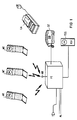
- a fixed part FT is in radio communication with up to three mobile parts MT. There is also a corded phone ST and a door intercom TSS connected as extensions to the fixed part FT.
- Charging trays LA which are set up individually or form part of the fixed part FT, are used to hold the mobile telephones MT. The rechargeable battery for the power supply of the mobile part MT is charged or the charge is held in the charging station LA. They can also be used to hold a spare battery.
- the exchange lines AL are connected via exchange rates AS and the corded telephone ST and the door intercom TSS via subscriber rates TS to a switching matrix KF in the fixed part.
- Switching circuits for example a direct dialing device to the extensions, are connected to the switching matrix KF.
- a door opener contact TK complements the door intercom TSS.
- a switching control VS not only controls the switching network KF, but also the further signal processing in a low-frequency and radio part NT, FKT.
- the high-frequency signals are emitted or received via an antenna AN.
- Each handset has its own device-specific identifier, which is exchanged with the fixed part. This process is monitored by the exchange control VS. Since each handset can thus be identified, it can be connected to another extension or to one of the trunk lines AL via the switching matrix KF. With a liquid crystal display in the handset, current information such as charges, calling or called number, incoming call with line number etc. can be displayed.
- the low-frequency part shown in FIG. 3 contains a signal processing path for each of the three mobile parts.
- each signal processing line is made up of an active hook switch GS, followed by a compander KP.
- the switching-related data such as, for example, the exchange of identifiers, are taken from the switching controller VS and added to the signal processing path. That happens mainly when setting up and clearing a connection between fixed and handset.
- a band filter BF limits the frequency band in order to avoid interference with an adjacent channel when transmitting.
- the switching data from the modem M are coupled in on the transmission side via the band filter BF.
- the modem M is directly connected on the receiving end.
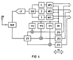
- Fig. 4 shows the continuation of the signal processing routes in the radio part.
- the low-frequency signal is modulated onto a carrier signal from the 900 MHz band. This takes place in a modulable frequency synthesizer MFS, which is stabilized by a reference oscillator R0 in a PLL circuit.
- the modulable frequency synthesizers MFS are connected to switches S, which only switch their output signal through after the transient process of about 1 ms.
- the high-frequency signals of the three signal processing links are added in a passive signal summing device SSV. It is built in 50-ohm technology and must be well decoupled and adapted. In this way, repercussions on the modulatable frequency synthesizers MFS are avoided.
- This sum signal is amplified by a linearized power amplifier LV, which has to work particularly linearly and without intermodulation.
- the sum signal is passed to the antenna AN and transmitted via a transmission / reception switch SEW.
- the signals received by the mobile parts are fed via the transmitting and receiving switch SEW to an active signal separation device STV. It is made up of three parallel amplifiers so that no additional losses occur on the received signal. Each of the three high-frequency signals is converted back into a low-frequency signal via carrier frequency synthesizer TFS and an intermediate frequency converter ZFU.
- the carrier frequency synthesizers TFS work in parallel to the modulatable frequency synthesizers MFS, cannot be modulated and generate a frequency that is matched to the carrier signal.
Landscapes
- Engineering & Computer Science (AREA)
- Computer Networks & Wireless Communication (AREA)
- Signal Processing (AREA)
- Mobile Radio Communication Systems (AREA)
- Soil Working Implements (AREA)
- Walking Sticks, Umbrellas, And Fans (AREA)
- Telephone Function (AREA)
- Fittings On The Vehicle Exterior For Carrying Loads, And Devices For Holding Or Mounting Articles (AREA)
- Telephone Set Structure (AREA)
Description
- Die Erfindung betrifft eine Vorrichtung zum schnurlosen Telefonieren, bestehend aus einem Festteil mit Funk- und Leitungsteil und mehreren Mobilteilen mit jeweils individueller, mit dem Festteil austauschbarer Kennung.
- In der EP-A-0 180 178 wird ein Schnurlos-Telefonsystem beschrieben, bei dem einem Festteil mehrere Mobilteile zugeordnet sind. Die Mobilteile unterscheiden sich durch ihre gerätespezifische Kennung. Einem Haupt-Mobilteil sind mehrere Neben-Mobilteile untergeordnet. Es ist nur vom Haupt-Mobilteil möglich, abgehende Gespräche zu führen und ankommende anzunehmen. Von den Neben-Mobilteilen können nur ankommende Gespräche entgegengenommen werden (siehe Seite 2 und Anspruch 1). Dadurch wird verhindert, daß von möglicherweise unbeaufsichtigten Mobilteilen abgehende Gespräche geführt werden, und der Teilnehmer mit Gebühren belastet wird.
- Aus der europäischen Patentanmeldung (EP-A-0 219 885) ist bereits eine schnurlose Nebenstellenanlage ("wireless PBX") bekannt. Diese Nebenstellenanlage weist eine Mehrzahl von Feststationen (Transceiver) auf, wobei jede Feststation jeweils nur mit einem zugeordneten Mobilteil kommuniziert.
- Ein Schnurlostelefon ist im telcom report 10 (1987), Heft 2, Seite 130-137 beschrieben. Es läßt sich auch als Nebenstelle statt eines Schnurtelefones in eine Nebenstellenanlage integrieren. Der technische und finanzielle Aufwand steigt jedoch beträchtlich, wenn mehrere Nebenstellen mit Schnurlostelefonen ausgestattet werden sollen. Für jeden dieser Teilnehmer ist eine spezielle Anschlußbaugruppe, ein Fest- und ein Mobilteil vorzusehen.
- Der Erfindung liegt die Aufgabe zugrunde, den technischen Aufwand beim Aufbau mehrerer Nebenstellen mit schnurlosen Telefonen zu verringern.
- Diese Aufgabe wird erfindungsgemäß mit den Merkmalen des Patentanspruchs 1 gelöst.
Mit einem Hochfrequenzteil und einer Antenne im Festteil kann gleichzeitig ein Duplexfunkkanal je Mobilteil aufgebaut werden, wodurch dieser eine Festteil mehrere Mobilteile versorgt. Jeder Mobilteil fungiert aufgrund der gerätespezifischen, unterschiedlichen Kennung trotz seines herkömmlichen Aufbaues als vollwertige Nebenstelle. Da eine vom Festteil unabhängige Ladeablage lediglich einen Netzstromanschluß benötigt, kann der Aufstellungsort einfacher geändert werden als bei dem mit der Amtsleitung verbundenen Festteil. Ein oder mehrere Ladeablagen können auch an dem Festteil angeformt oder lösbar mit ihm verbunden sein. Am Leitungsteil können sowohl Amtsleitungen, als auch Querverbindungsleitungen zu einer übergeordneten Nebenstellananlage angeschlossen werden. - Zur Gestaltung einer Heimtelefonanlage ist am Koppelfeld mindestens ein Teilnehmersatz für ein Schnurtelefon und/oder eine Türsprechstelle angeschlossen. Damit ist auch eine Anpassung an unterschiedliche nationale Postvorschriften möglich. Die Leistungsfähigkeit der Nebenstellenanlage wird dadurch erhöht, daß der Festteil mit einer Durchwahlvorrichtung zu den Nebenstellen bestückt ist. Dieses Leistungsmerkmal ist ein Beispiel für die Ausbaufähigkeit der Nebenstellenanlage mit schnurlosen Teilnehmeranschlüssen.
- Die Erfindung wird anhand eines Ausführungsbeispieles mit Zeichnungen näher erläutert. Es zeigen:
- Fig.1
- die Darstellung der Ausbaustufe des Ausführungsbeispiels,
- Fig.2
- ein Blockschaltbild seines Festteiles,
- Fig.3
- das detailliertere Blockschaltbild des Niederfrequenzteiles im Festteil und
- Fig.4
- das detailliertere Blockschaltbild des Funkteiles des Festteiles.
- Die Fig.1 zeigt eine Nebenstellenanlage, die an zwei Amtsleitungen AL angeschlossen ist. Ein Festteil FT steht mit bis zu drei Mobilteilen MT in Funkverbindung. Darüberhinaus sind ein Schnurtelefon ST und eine Türsprechstelle TSS als Nebenstellen mit dem Festteil FT verbunden. Zur Aufnahme der Mobiltelefone MT dienen Ladeablagen LA, die einzeln aufgestellt sind oder einen Teil des Festteiles FT bilden. In der Ladeablage LA wird der Akkumulator zur Stromversorgung des Mobilteiles MT aufgeladen bzw. die Ladung gehalten. Sie können auch der Aufnahme eines Reserve-Akkumulators dienen.
- Wie Fig.2 zeigt, sind die Amtsleitungen AL über Amtssätze AS und das Schnurtelefon ST und die Türsprechstelle TSS über Teilnehmersätze TS mit einem Koppelfeld KF im Festteil verbunden. Vermittlungstechnische Schaltungen, beispielsweise eine Durchwahlvorrichtung zu den Nebenstellen, sind an das Koppelfeld KF angeschlossen Ein Türöffnerkontakt TK ergänzt die Türsprechstelle TSS.
- Eine Vermittlungssteuerung VS steuert nicht nur das Koppelfeld KF, sondern auch die weitere Signalverarbeitung in einem Niederfrequenz- und Funkteil NT, FKT. Die Hochfrequenzsignale werden über eine Antenne AN abgestrahlt bzw. empfangen. Jeder Mobilteil verfügt über seine eigene gerätespezifische Kennung, die mit dem Festteil ausgetauscht wird. Dieser Vorgang wird von der Vermittlungssteuerung VS überwacht. Da somit jeder Mobilteil identifizierbar ist, kann er über das Koppelfeld KF mit einer anderen Nebenstelle oder einer der Amtsleitungen AL verbunden werden. Mit einer Flüssigkristallanzeige im Mobilteil können aktuelle Informationen, wie Gebühren, rufende oder gerufene Nummer, ankommender Ruf mit Leitungsnummer etc. angezeigt werden.
- Der in Fig.3 dargestellte Niederfrequenzteil enthält eine Signalverarbeitungsstrecke für jeden der drei Mobilteile. Nach dem Koppelfeld KF ist jede Signalverarbeitungsstrecke aus einem aktiven Gabelschalter GS aufgebaut, auf den ein Kompander KP folgt. Über ein Modem M werden der Signalverarbeitungsstrecke die vermittlungstechnischen Daten, wie beispielsweise der Kennungsaustausch, von der Vermittlungssteuerung VS entnommen und hinzugefügt. Das erfolgt hauptsächlich beim Auf- und Abbau einer Verbindung zwischen Fest-und Mobilteil. Ein Bandfilter BF begrenzt das Frequenzband, um beim Senden Überlagerungen mit einem benachbarten Kanal zu vermeiden. Darüberhinaus werden über das Bandfilter BF die vermittlungstechnischen Daten vom Modem M sendeseitig eingekoppelt. Empfangsseitig ist das Modem M direkt angeschlossen.
- Fig.4 zeigt die Fortsetzung der Signalverarbeitungsstrecken im Funkteil. Sendeseitig wird das Niederfrequenzsignal einem Trägersignal aus dem 900 MHz-Band aufmoduliert. Das erfolgt in einem modulierbaren Frequenzsynthesizer MFS, der von einem Referenzoszillator R0 in PLL-Schaltung stabilisiert wird. Die modulierbaren Frequenzsynthesizer MFS sind mit Schaltern S verbunden, die ihr Ausgangssignal erst nach dem Einschwingvorgang von etwa 1 ms durchschalten. Die Hochfrequenzsignale der drei Signalverarbeitungsstrecken werden in einer passiven Signalsummiervorrichtung SSV addiert. Sie ist in 50-Ohm-Technik aufgebaut und muß gut entkoppelt und angepaßt sein. So werden bei der Summierung Rückwirkungen auf die modulierbaren Frequenzsynthesizer MFS vermieden. Dieses Summensignal wird von einem linearisierten Leistungsverstärker LV verstärkt, der besonders linear und ohne Intermodulation arbeiten muß. Über eine Sende/Empfangsweiche SEW wird das Summensignal zur Antenne AN geleitet und abgestrahlt.
- Die von den Mobilteilen empfangenen Signale werden über die Sende/ und Empfangsweiche SEW einer aktiven Signaltrennvorrichtung STV zugeleitet. Sie ist aus drei parallelen Verstärkern aufgebaut, damit am Empfangssignal keine zusätzlichen Verluste auftreten. Jedes der drei Hochfrequenzsignale wird über Trägerfrequenzsynthesizer TFS und einen Zwischenfrequenzumsetzer ZFU in ein Niederfrequenzsignal rückgewandelt. Die Trägerfrequenzsynthesizer TFS arbeiten parallel zu den modulierbaren Frequenzsynthesizern MFS, sind nicht modulierbar und erzeugen eine auf das Trägersignal abgestimmte Frequenz.
Claims (6)
- Vorrichtung zum schnurlosen Telefonieren, bestehend aus einem Festteil (FT) mit Funk- und Leitungsteil und mehreren Mobilteilen (MT) mit jeweils individueller, mit dem Festteil (FT) austauschbarer Kennung,
dadurch gekennzeichnet,
daß der Festteil (FT) ein Koppelfeld (KF) aufweist, über das, gesteuert durch eine Vermittlungssteuerung (VS) Verbindungen der Mobilteile (MT) untereinander, Verbindungen zwischen Mobilteilen (MT) und weiteren Nebenstellen (ST,TSS) des als Nebenstellenanlage ausgebildeten Festteils (FT) und Verbindungen zwischen Mobilteilen (MT) und Amtsleitungen (AL) herstellbar sind,
daß der Festteil (FT) je Mobilteil (MT) eine Signalverarbeitungsstrecke aufweist, und
daß im Funkteil des Festteiles (FT) die Signalverarbeitungsstrecken mit einer von der Vermittlungssteuerung (VS) gesteuerten sendeseitigen Signalsummiervorrichtung (SSV) und einer empfangsseitigen Signaltrennungsvorrichtung (STV) verbunden sind. - Vorrichtung nach Anspruch 1,
dadurch gekennzeichnet,
daß am Koppelfeld (KF) mindestens ein Teilnehmersatz (TS) für ein Schnurtelefon (ST) und/oder eine Türsprechstelle (TSS) angeschlossen ist. - Vorrichtung nach Anspruch 1 oder 2,
dadurch gekennzeichnet,
daß der Festteil (FT) mit einer Durchwahlvorrichtung zu den Nebenstellen (MT,ST) bestückt ist. - Vorrichtung nach einem der Ansprüche 1 bis 3, dadurch ge kennzeichnet, daß für Mobilteile (MT) jeweils eine vom Festteil (FT) unabhängige oder eine einen Teil des Festteils (FT) bildende Ladeablage (LA) vorhanden ist.
- Vorrichtung nach Anspruch 4,
dadurch gekennzeichnet,
daß die Ladeablage (LA) einen Reserve-Akkumulator zur Stromversorgung des Mobilteils (MT) aufnimmt. - Vorrichtung zum schnurlosen Telefonieren nach einem der vorstehenden Ansprüche,
dadurch gekennzeichnet,
daß Mobilteile (MT) jeweils eine Flüssigkeitskristallanzeige zur optischen Darstellung von Informationen aufweisen.
Applications Claiming Priority (2)
| Application Number | Priority Date | Filing Date | Title |
|---|---|---|---|
| AT0133988A AT390702B (de) | 1988-05-20 | 1988-05-20 | Vorrichtung zum schnurlosen telefonieren |
| AT1339/88 | 1988-05-20 |
Publications (3)
| Publication Number | Publication Date |
|---|---|
| EP0342707A2 EP0342707A2 (de) | 1989-11-23 |
| EP0342707A3 EP0342707A3 (de) | 1992-04-01 |
| EP0342707B1 true EP0342707B1 (de) | 1994-12-14 |
Family
ID=3511760
Family Applications (1)
| Application Number | Title | Priority Date | Filing Date |
|---|---|---|---|
| EP89109104A Expired - Lifetime EP0342707B1 (de) | 1988-05-20 | 1989-05-19 | Vorrichtung zum schnurlosen Telefonieren |
Country Status (3)
| Country | Link |
|---|---|
| EP (1) | EP0342707B1 (de) |
| AT (2) | AT390702B (de) |
| DE (1) | DE58908757D1 (de) |
Cited By (10)
| Publication number | Priority date | Publication date | Assignee | Title |
|---|---|---|---|---|
| US7149514B1 (en) | 1997-07-30 | 2006-12-12 | Bellsouth Intellectual Property Corp. | Cellular docking station |
| US8000682B2 (en) | 2002-07-15 | 2011-08-16 | At&T Intellectual Property I, L.P. | Apparatus and method for restricting access to data |
| US8046007B2 (en) | 2001-12-26 | 2011-10-25 | At&T Intellectual Property I, L.P. | Auto sensing home base station for mobile telephone with remote answering capabilities |
| US8243908B2 (en) | 2002-07-15 | 2012-08-14 | At&T Intellectual Property I, Lp | Systems and methods for restricting the use and movement of telephony devices |
| US8249570B2 (en) | 1997-07-30 | 2012-08-21 | At&T Intellectual Property I, L.P. | Apparatus, method, and computer-readable medium for interfacing devices with communications networks |
| US8275371B2 (en) | 2002-07-15 | 2012-09-25 | At&T Intellectual Property I, L.P. | Apparatus and method for providing communications and connection-oriented services to devices |
| US8416804B2 (en) | 2002-07-15 | 2013-04-09 | At&T Intellectual Property I, L.P. | Apparatus and method for providing a user interface for facilitating communications between devices |
| US8526466B2 (en) | 2002-07-15 | 2013-09-03 | At&T Intellectual Property I, L.P. | Apparatus and method for prioritizing communications between devices |
| US8543098B2 (en) | 2002-07-15 | 2013-09-24 | At&T Intellectual Property I, L.P. | Apparatus and method for securely providing communications between devices and networks |
| US8554187B2 (en) | 2002-07-15 | 2013-10-08 | At&T Intellectual Property I, L.P. | Apparatus and method for routing communications between networks and devices |
Families Citing this family (12)
| Publication number | Priority date | Publication date | Assignee | Title |
|---|---|---|---|---|
| DE4000859A1 (de) * | 1990-01-13 | 1991-07-18 | Hagenuk Telecom Gmbh | Vorrichtung zum betreiben von schnurlosen telefonen |
| JP3025712B2 (ja) * | 1991-05-20 | 2000-03-27 | パイオニアコミュニケーションズ株式会社 | コードレス電話の子機間通話方式 |
| JP2954389B2 (ja) * | 1991-06-06 | 1999-09-27 | パイオニアコミュニケーションズ株式会社 | コードレス電話の子機間転送装置 |
| CA2082244C (en) * | 1992-01-08 | 1996-09-03 | Samuel Rocco Paniccia Jr. | Two-handset cordless telephone system |
| CA2085722C (en) * | 1992-01-08 | 1997-02-25 | Samuel Rocco Paniccia Jr. | Use of a vcxo in the base unit of a two-handset cordless telephone system |
| DE4207775A1 (de) * | 1992-03-11 | 1993-09-16 | Philips Patentverwaltung | Aus schnurlosen telefonen gebildete nebenstellenanlage |
| DE9311289U1 (de) * | 1993-07-28 | 1993-09-09 | Siemens AG, 80333 München | Kleines Telekommunikationssystem, insbesondere Heimtelefonsystem |
| US5528666A (en) * | 1994-07-01 | 1996-06-18 | Motorola, Inc. | Personal phone expansion system |
| EP0910916B1 (de) | 1996-07-11 | 2003-10-15 | BRITISH TELECOMMUNICATIONS public limited company | Schnurloses telefongerät |
| WO1998003003A1 (en) * | 1996-07-11 | 1998-01-22 | British Telecommunications Public Limited Company | Telephone apparatus |
| US7194083B1 (en) | 2002-07-15 | 2007-03-20 | Bellsouth Intellectual Property Corporation | System and method for interfacing plain old telephone system (POTS) devices with cellular networks |
| US6411802B1 (en) | 1999-03-15 | 2002-06-25 | Bellsouth Intellectual Property Management Corporation | Wireless backup telephone device |
Family Cites Families (12)
| Publication number | Priority date | Publication date | Assignee | Title |
|---|---|---|---|---|
| JPS581843B2 (ja) * | 1977-10-14 | 1983-01-13 | 日本電信電話株式会社 | 陸上移動無線基地局送信アンテナ共用方式 |
| DE3004817A1 (de) * | 1980-02-09 | 1981-08-20 | Deutsche Bundespost vertreten durch den Präsidenten des Fernmeldetechnischen Zentralamtes, 6100 Darmstadt | Schaltungsanordnung zum gegeneinander entkoppelten anschalten mehrerer sender an ein antennensystem |
| GB2138652B (en) * | 1983-04-23 | 1986-04-23 | Standard Telephones Cables Ltd | Distributed pabx |
| US4731813A (en) * | 1983-12-30 | 1988-03-15 | Motorola, Inc. | Address encoding system for portable battery-operated devices |
| JPS60223340A (ja) * | 1984-04-20 | 1985-11-07 | Sony Corp | コ−ドレステレホン |
| ATE38751T1 (de) * | 1984-06-14 | 1988-12-15 | Airtech Ltd | Vielfachkopplersystem. |
| GB2166622A (en) * | 1984-09-14 | 1986-05-08 | British Telecomm | Cordless telephone system |
| JPS61105138A (ja) * | 1984-10-29 | 1986-05-23 | Nec Corp | 無線電話装置 |
| GB8521159D0 (en) * | 1985-08-23 | 1985-10-02 | Pa Consulting Services | Two-way radio communications system |
| KR870004587A (ko) * | 1985-10-16 | 1987-05-11 | 엘리 와이스 | 무선 근거리 통신 장치 |
| JPH06101698B2 (ja) * | 1986-04-25 | 1994-12-12 | 日本電気株式会社 | 無線電話装置 |
| JPH0815350B2 (ja) * | 1986-05-09 | 1996-02-14 | 日本電気株式会社 | 無線電話装置 |
-
1988
- 1988-05-20 AT AT0133988A patent/AT390702B/de not_active IP Right Cessation
-
1989
- 1989-05-19 DE DE58908757T patent/DE58908757D1/de not_active Expired - Lifetime
- 1989-05-19 EP EP89109104A patent/EP0342707B1/de not_active Expired - Lifetime
- 1989-05-19 AT AT89109104T patent/ATE115804T1/de not_active IP Right Cessation
Cited By (13)
| Publication number | Priority date | Publication date | Assignee | Title |
|---|---|---|---|---|
| US7149514B1 (en) | 1997-07-30 | 2006-12-12 | Bellsouth Intellectual Property Corp. | Cellular docking station |
| US9258845B2 (en) | 1997-07-30 | 2016-02-09 | At&T Intellectual Property I, L.P. | Cellular docking station |
| US8249570B2 (en) | 1997-07-30 | 2012-08-21 | At&T Intellectual Property I, L.P. | Apparatus, method, and computer-readable medium for interfacing devices with communications networks |
| US8046007B2 (en) | 2001-12-26 | 2011-10-25 | At&T Intellectual Property I, L.P. | Auto sensing home base station for mobile telephone with remote answering capabilities |
| US8515417B2 (en) | 2001-12-26 | 2013-08-20 | At&T Intellectual Property I, L.P. | Auto sensing home base station for mobile telephone with remote answering capabilities |
| US8416804B2 (en) | 2002-07-15 | 2013-04-09 | At&T Intellectual Property I, L.P. | Apparatus and method for providing a user interface for facilitating communications between devices |
| US8275371B2 (en) | 2002-07-15 | 2012-09-25 | At&T Intellectual Property I, L.P. | Apparatus and method for providing communications and connection-oriented services to devices |
| US8243908B2 (en) | 2002-07-15 | 2012-08-14 | At&T Intellectual Property I, Lp | Systems and methods for restricting the use and movement of telephony devices |
| US8526466B2 (en) | 2002-07-15 | 2013-09-03 | At&T Intellectual Property I, L.P. | Apparatus and method for prioritizing communications between devices |
| US8543098B2 (en) | 2002-07-15 | 2013-09-24 | At&T Intellectual Property I, L.P. | Apparatus and method for securely providing communications between devices and networks |
| US8554187B2 (en) | 2002-07-15 | 2013-10-08 | At&T Intellectual Property I, L.P. | Apparatus and method for routing communications between networks and devices |
| US8885666B2 (en) | 2002-07-15 | 2014-11-11 | At&T Intellectual Property I, L.P. | Apparatus and method for providing a user interface for facilitating communications between devices |
| US8000682B2 (en) | 2002-07-15 | 2011-08-16 | At&T Intellectual Property I, L.P. | Apparatus and method for restricting access to data |
Also Published As
| Publication number | Publication date |
|---|---|
| EP0342707A3 (de) | 1992-04-01 |
| EP0342707A2 (de) | 1989-11-23 |
| ATE115804T1 (de) | 1994-12-15 |
| ATA133988A (de) | 1989-11-15 |
| AT390702B (de) | 1990-06-25 |
| DE58908757D1 (de) | 1995-01-26 |
Similar Documents
| Publication | Publication Date | Title |
|---|---|---|
| AT390702B (de) | Vorrichtung zum schnurlosen telefonieren | |
| DE69428191T2 (de) | Steuerungsverfahren fuer eine teilnehmerstation in einem funksystem | |
| EP0466736B1 (de) | Schnurlos-telefonsystem mit einer nebenstellen-kommunikationsanlage | |
| DE69120204T2 (de) | Mobiles Funkkommunikationssystem mit mobiler Basisstation und tragbares Gerät als Mobilstation | |
| DE3783789T2 (de) | Selektiv in voll-duplex- und halb-duplex-mode arbeitendes radiotelefonsystem mit mehreren eingaengen. | |
| DE3687727T2 (de) | Kommunikationssystem mit Bürodiensten für mobile Teilnehmer in einem Zellularsystem. | |
| DE69321858T2 (de) | Adapter zum Koppeln eines tragbaren Funktelefons an ein Mobiltelefon | |
| DE69414818T2 (de) | Verfahren, mobilvermittlung und teilnehmerstation in einem mobilfunksystem zum verbindungsaufbau eines hochprioritaetsanrufs | |
| DE69730493T2 (de) | Alternatives leitweglenkungssystem für mobiltelefongespräche | |
| EP0647074A2 (de) | Festes zellulares Kommunikationssystem | |
| DE69228859T2 (de) | Mobiles Kommunikationssystem mit zentraler Funkrufstation zum Anruf von mobilen Teilnehmern durch Basisstationen | |
| DE3781934T2 (de) | Schnurloses fernsprechersystem. | |
| DE69730994T2 (de) | Rufverwaltung in einem schnurlosen übertragungssystem | |
| EP0849965A1 (de) | Telefonvorrichtung | |
| DE69116949T2 (de) | Verfahren und Vorrichtung zur drahtlosen Kommunikation zwischen entfernten Lagen | |
| EP0476755B1 (de) | Fernsprechapparat für ein dienstintegriertes digitales Nachrichtennetz (ISDN) | |
| US3975594A (en) | Apparatus utilizing a phantom circuit for connecting additional subscribers to a telecommunication system | |
| EP0506795B1 (de) | Funkkommunikationsnetz auf basis digitaler ortsvermittlungsstellen | |
| DE10359908A1 (de) | Drahtloses Telefon | |
| DE69513322T2 (de) | Zellulares Festendgerät | |
| DE3787597T2 (de) | Mobiles Kommunikationssystem zur Vermeidung von Interferenz mit dem Steuerkanal. | |
| DE69310432T2 (de) | Anschlusseinheit zum Verbinden eines oder mehrerer konventioneller Telefonapparate an ein zellulares Funknetz | |
| EP0623273A1 (de) | Vermittlungseinrichtung und -verfahren für ein funktelefoniersystem mit dem charakter einer orts- oder nebenstellenvermittlung | |
| EP0630140A2 (de) | Schnurloses Telefon | |
| DE69217238T2 (de) | Schnurlose schnittstelle. |
Legal Events
| Date | Code | Title | Description |
|---|---|---|---|
| PUAI | Public reference made under article 153(3) epc to a published international application that has entered the european phase |
Free format text: ORIGINAL CODE: 0009012 |
|
| AK | Designated contracting states |
Kind code of ref document: A2 Designated state(s): AT CH DE GB LI |
|
| 17P | Request for examination filed |
Effective date: 19901220 |
|
| PUAL | Search report despatched |
Free format text: ORIGINAL CODE: 0009013 |
|
| AK | Designated contracting states |
Kind code of ref document: A3 Designated state(s): AT CH DE GB LI |
|
| 17Q | First examination report despatched |
Effective date: 19921016 |
|
| GRAA | (expected) grant |
Free format text: ORIGINAL CODE: 0009210 |
|
| AK | Designated contracting states |
Kind code of ref document: B1 Designated state(s): AT CH DE GB LI |
|
| REF | Corresponds to: |
Ref document number: 115804 Country of ref document: AT Date of ref document: 19941215 Kind code of ref document: T |
|
| REF | Corresponds to: |
Ref document number: 58908757 Country of ref document: DE Date of ref document: 19950126 |
|
| GBT | Gb: translation of ep patent filed (gb section 77(6)(a)/1977) |
Effective date: 19950217 |
|
| PLBI | Opposition filed |
Free format text: ORIGINAL CODE: 0009260 |
|
| 26 | Opposition filed |
Opponent name: INTERESSENGEMEINSCHAFT FUER RUNDFUNKSCHUTZRECHTE G Effective date: 19950914 |
|
| PLBF | Reply of patent proprietor to notice(s) of opposition |
Free format text: ORIGINAL CODE: EPIDOS OBSO |
|
| PLBF | Reply of patent proprietor to notice(s) of opposition |
Free format text: ORIGINAL CODE: EPIDOS OBSO |
|
| PLBO | Opposition rejected |
Free format text: ORIGINAL CODE: EPIDOS REJO |
|
| PLBN | Opposition rejected |
Free format text: ORIGINAL CODE: 0009273 |
|
| STAA | Information on the status of an ep patent application or granted ep patent |
Free format text: STATUS: OPPOSITION REJECTED |
|
| 27O | Opposition rejected |
Effective date: 19970804 |
|
| REG | Reference to a national code |
Ref country code: GB Ref legal event code: IF02 |
|
| PGFP | Annual fee paid to national office [announced via postgrant information from national office to epo] |
Ref country code: AT Payment date: 20080416 Year of fee payment: 20 |
|
| PGFP | Annual fee paid to national office [announced via postgrant information from national office to epo] |
Ref country code: DE Payment date: 20080721 Year of fee payment: 20 Ref country code: CH Payment date: 20080807 Year of fee payment: 20 |
|
| PGFP | Annual fee paid to national office [announced via postgrant information from national office to epo] |
Ref country code: GB Payment date: 20080519 Year of fee payment: 20 |
|
| REG | Reference to a national code |
Ref country code: CH Ref legal event code: PFA Owner name: SIEMENS AKTIENGESELLSCHAFT Free format text: SIEMENS AKTIENGESELLSCHAFT#WITTELSBACHERPLATZ 2#D-80333 MUENCHEN (DE) -TRANSFER TO- SIEMENS AKTIENGESELLSCHAFT#WITTELSBACHERPLATZ 2#D-80333 MUENCHEN (DE) |
|
| REG | Reference to a national code |
Ref country code: CH Ref legal event code: PL |
|
| REG | Reference to a national code |
Ref country code: GB Ref legal event code: PE20 Expiry date: 20090518 |
|
| PG25 | Lapsed in a contracting state [announced via postgrant information from national office to epo] |
Ref country code: GB Free format text: LAPSE BECAUSE OF EXPIRATION OF PROTECTION Effective date: 20090518 |