EP0342513B1 - Gas detecting method and system - Google Patents
Gas detecting method and system Download PDFInfo
- Publication number
- EP0342513B1 EP0342513B1 EP89108443A EP89108443A EP0342513B1 EP 0342513 B1 EP0342513 B1 EP 0342513B1 EP 89108443 A EP89108443 A EP 89108443A EP 89108443 A EP89108443 A EP 89108443A EP 0342513 B1 EP0342513 B1 EP 0342513B1
- Authority
- EP
- European Patent Office
- Prior art keywords
- histogram
- threshold value
- gas
- sensor output
- detection threshold
- Prior art date
- Legal status (The legal status is an assumption and is not a legal conclusion. Google has not performed a legal analysis and makes no representation as to the accuracy of the status listed.)
- Expired - Lifetime
Links
- 238000000034 method Methods 0.000 title claims description 14
- 238000001514 detection method Methods 0.000 claims description 45
- 230000004044 response Effects 0.000 claims description 3
- 239000007789 gas Substances 0.000 description 43
- 230000007423 decrease Effects 0.000 description 6
- 238000010586 diagram Methods 0.000 description 5
- 238000005070 sampling Methods 0.000 description 4
- 239000004065 semiconductor Substances 0.000 description 4
- UGFAIRIUMAVXCW-UHFFFAOYSA-N Carbon monoxide Chemical compound [O+]#[C-] UGFAIRIUMAVXCW-UHFFFAOYSA-N 0.000 description 3
- QVGXLLKOCUKJST-UHFFFAOYSA-N atomic oxygen Chemical compound [O] QVGXLLKOCUKJST-UHFFFAOYSA-N 0.000 description 3
- 230000006399 behavior Effects 0.000 description 3
- 229910002091 carbon monoxide Inorganic materials 0.000 description 3
- 239000003344 environmental pollutant Substances 0.000 description 3
- 239000001301 oxygen Substances 0.000 description 3
- 229910052760 oxygen Inorganic materials 0.000 description 3
- 231100000719 pollutant Toxicity 0.000 description 3
- 239000002341 toxic gas Substances 0.000 description 3
- XLYOFNOQVPJJNP-UHFFFAOYSA-N water Chemical compound O XLYOFNOQVPJJNP-UHFFFAOYSA-N 0.000 description 3
- ATUOYWHBWRKTHZ-UHFFFAOYSA-N Propane Chemical compound CCC ATUOYWHBWRKTHZ-UHFFFAOYSA-N 0.000 description 2
- MCMNRKCIXSYSNV-UHFFFAOYSA-N Zirconium dioxide Chemical compound O=[Zr]=O MCMNRKCIXSYSNV-UHFFFAOYSA-N 0.000 description 2
- 238000006243 chemical reaction Methods 0.000 description 2
- 239000001257 hydrogen Substances 0.000 description 2
- 229910052739 hydrogen Inorganic materials 0.000 description 2
- 125000004435 hydrogen atom Chemical class [H]* 0.000 description 2
- 229910044991 metal oxide Inorganic materials 0.000 description 2
- VNWKTOKETHGBQD-UHFFFAOYSA-N methane Chemical compound C VNWKTOKETHGBQD-UHFFFAOYSA-N 0.000 description 2
- 238000002360 preparation method Methods 0.000 description 2
- 238000009423 ventilation Methods 0.000 description 2
- CBENFWSGALASAD-UHFFFAOYSA-N Ozone Chemical compound [O-][O+]=O CBENFWSGALASAD-UHFFFAOYSA-N 0.000 description 1
- XOLBLPGZBRYERU-UHFFFAOYSA-N SnO2 Inorganic materials O=[Sn]=O XOLBLPGZBRYERU-UHFFFAOYSA-N 0.000 description 1
- -1 SnO2 metal-oxide Chemical class 0.000 description 1
- 238000004378 air conditioning Methods 0.000 description 1
- AQTIRDJOWSATJB-UHFFFAOYSA-K antimonic acid Chemical compound O[Sb](O)(O)=O AQTIRDJOWSATJB-UHFFFAOYSA-K 0.000 description 1
- 239000003054 catalyst Substances 0.000 description 1
- 238000007084 catalytic combustion reaction Methods 0.000 description 1
- 238000002485 combustion reaction Methods 0.000 description 1
- 239000004020 conductor Substances 0.000 description 1
- 238000010276 construction Methods 0.000 description 1
- 238000001816 cooling Methods 0.000 description 1
- 230000003247 decreasing effect Effects 0.000 description 1
- 230000006866 deterioration Effects 0.000 description 1
- 238000010438 heat treatment Methods 0.000 description 1
- 239000000463 material Substances 0.000 description 1
- 150000004706 metal oxides Chemical class 0.000 description 1
- 239000003960 organic solvent Substances 0.000 description 1
- 230000001590 oxidative effect Effects 0.000 description 1
- 239000001294 propane Substances 0.000 description 1
- 238000000746 purification Methods 0.000 description 1
Images


Classifications
-
- G—PHYSICS
- G01—MEASURING; TESTING
- G01N—INVESTIGATING OR ANALYSING MATERIALS BY DETERMINING THEIR CHEMICAL OR PHYSICAL PROPERTIES
- G01N33/00—Investigating or analysing materials by specific methods not covered by groups G01N1/00 - G01N31/00
- G01N33/0004—Gaseous mixtures, e.g. polluted air
- G01N33/0009—General constructional details of gas analysers, e.g. portable test equipment
- G01N33/0062—General constructional details of gas analysers, e.g. portable test equipment concerning the measuring method or the display, e.g. intermittent measurement or digital display
- G01N33/0063—General constructional details of gas analysers, e.g. portable test equipment concerning the measuring method or the display, e.g. intermittent measurement or digital display using a threshold to release an alarm or displaying means
Definitions
- the present invention relates to detection of gases such as combustible gas, toxic gas, oxygen and water vapor.
- sensor output refers to an output which increases when the sensor detects a gas. However, the result can be reverse depending on the type of sensor used.
- U.S. Patent No. 4,437,391 discloses a detection threshold value as determined based on the minimum value of sensor outputs. According to U.S. Patent No. 4,352,321, the sensor output is sampled at an interval of 1 minute to determine a detection threshold value based on the values obtained.
- US-A-4827154 discloses that a detection threshold value is to be determined based on the minimum value of gas sensor outputs during a predetermined interval and that the threshold value is to be altered on saturation of the gas sensor output.
- the detection threshold value can be determined automatically when gas sensor outputs in the past are used for the determination. This eliminates the need to repeatedly determine the threshold value for a plurality of sensors. If the sensor output varies, for example, with time, the detection threshold value also varies automatically in accordance with the variation and can therefore be made automatically free of the influence of the output variation.
- the detection threshold value What matters is the meaning of the detection threshold value.
- the sensor output increases when the ambient atmosphere is polluted and decreases when it is cleaned. Attention is directed to the minimum output value to determine the detection threshold value using an output reflecting the cleanest atmosphere.
- the sensor output nevertheless is affected, for example, by temporary cooling of the sensor due to a flow of air, variations in the power supply voltage and variations in the ambient temperature and humidity. Accordingly, the minimum value, if merely used, is likely to afford an unrealistic detection threshold value.
- a long period of time when elapsing after the sampling of the minimum value, involves variations in the ambient temperature or humidity or the like, giving rise to a need to alter the detection threshold value.
- the threshold value can not be modified when attention is merely directed to the minimum value only. For example, in the case where the sensor output gradually increases after the minimum value has been sampled, it is impossible to recognize whether the output increase indicates gradual pollution of the atmosphere or a mere increase in the ambient temperature or humidity.
- the detection threshold value is determined by sampling the sensor output every minute, the meaning of the threshold value determined is totally ambiguous. For example, a polluted atmosphere can be detected with reference to a detection threshold value which is determined from output values of a sensor exposed to this atmosphere. Furthermore, the threshold value fails to reflect the sensor output more than one minute ago.
- An object of the present invention is to determine a detection threshold value on the basis of the overall sensor output behavior in the past, and to obtain the threshold value free of the influence of the incidental variations in the sensor output.
- the present invention provides a method of detecting a gas by comparing a gas sensor output with a gas detection threshold value determined based on gas sensor outputs in the past, the method being characterized in that the detection threshold value is determined from a histogram of the gas sensor outputs in the past.
- the histogram is converted to the detection threshold value, for example, by using the modal sensor output for the maximum frequency on the histogram, a sensor output corresponding to the median on the histogram, a mean sensor output value determined from the histogram.
- the detection threshold value is obtained, for example, by increasing such a value at a suitable ratio.
- the modal sensor output remains unchanged even if the sensor output varies for an incidental reason.
- the mode is more preferable than the median or mean.
- the median or the mean sensor output value determined from the histogram involves the influence of the pollution.
- the modal sensor output is not appreciably affected by the pollution because the atmosphere is seldom polluted to a definite concentration at all times, such that the histogram has two peaks, i.e., a peak for the clean atmosphere and a peak for the polluted atmosphere.
- the peak for the polluted atmosphere is broad and concealed by the base of the peak for the clean atmosphere.
- the detection threshold value when determined with attention focused on the mode, can therefore be less affected by the pollution of the background.
- the width of the histogram corresponds to the degree of changes in the atmosphere. For example, with an environment wherein the background itself is polluted, variations in the background gas concentration give the histogram an increased distribution, which it is desirable to use for modifying the detection threshold value. For example, the threshold value determined from the mode on the histogram is decreased in accordance with the distribution width of the histogram.
- the histogram shows the overall sensor output behavior in the past, whereas the mean value or the like of sensor outputs in the past, if used, fails to reflect the data other than the mean value or the like. Furthermore, the memory needed for preparing the histogram can be small and will not greatly burden the control circuit.
- the system for practicing the method of the present invention comprises, for example, an A/D converter for subjecting the sensor output to A/D conversion, means for preparing a histogram with use of the converted output, means for determining a detection threshold value from the histogram, and means for comparing the threshold value with a sensor output to detect a gas.
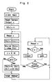
- Figs. 1 to 3 show a first embodiment.
- indicated at 2 is a suitable power supply for giving an output Vcc to the entire system, and at 4 a gas sensor comprising an SnO2 metal-oxide semiconductor 6 and a heater 8 for heating the semiconductor.
- the resistance value of the metal-oxide semiconductor 6 decreases with an increase in the concentration of a combustible gas, carbon monoxide or like toxic gas, water vapor or the like in the ambient atmosphere.
- the resistance value of the semiconductor 6 further increases with an increase in the concentration of oxygen, NO x or ozone in the atmosphere.
- These gases are detected by the gas sensor 4.
- Indicated at 10 is a loading resistor for the gas sensor 4,and the voltage v applied thereto serves as the sensor output.
- the gas sensor 4 can be optional in its type, material and construction.
- antimonic acid or like proton conductor may be used for the gas sensor for detecting hydrogen, carbon monoxide, water vapor or the like.
- the sensor may be of the catalytic combustion type including an oxidizing catalyst for burning a combustible gas by contact therewith and a Pt coil or like temperature measuring resistor for detecting the resulting heat of combustion.
- the sensor is used for detecting methane, hydrogen, propane or like combustible gas, or carbon monoxide or like toxic gas.
- the gas sensor can of course be a ZrO2 or like oxygen sensor, controlled potential electrolytic sensor or the like.
- Indicated at 12 is a signal processing microcomputer, at 14 an A/D converter for subjecting the sensor output v to A/D conversion, at 16 an arithmetic and logic unit, at 18 a clock signal generator, and at 20 a ROM having an operation program stored therein.
- a RAM 22 has a timer for determining a sampling interval for preparing histograms, memory means for storing the values D(v) of the histogram, etc.
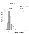
- the histogram shows, for example, sensor output values v as classified at an interval of ⁇ v into groups each with a frequency D(v).
- the memory required for preparing the histogram is relatively small.
- 100 signals in the past are to be stored.
- the memory required is of 10 x 5, i.e., 50 bits.
- 100 x 3 use of 3-bit signals corresponding to 10% accuracy
- 300-bit memory is required.
- the RAM 22 also stores the modal sensor output M of the histogram, a detection threshold value J obtained by multiplying the mode M by a constant K, a gas detection signal, etc.
- the constant K is made variable and can be entered from outside with a switch 24.
- the modal output M may be converted to the threshold value J by a desired method, for example, by adding a constant to M.
- the RAM 22 also stores therein flag signals including the gas detection signal. In response to the gas detection signal, an external load 26, such as an air conditioner, gas leak alarm buzzer or the like, is controlled.
- a histogram of initial distribution is prepared by plotting a frequency D(v) of n at a point for the initial sensor output v and a frequency of 0 at the other points.
- the histogram of initial distribution may be prepared, for example, by plotting the frequency of n for v, a frequency of n/2 on each side thereof, and further a grequency of 3/n for the next adjacent group on each side.
- the histogram of initial distribution only may be plotted without conducting any gas detecting operation for a suitable period of time following the energization of the system. A desired initial distribution may be plotted on the histogram.
- the current sensor output v is read, and 1 is added to the frequency D(v) corresponding to the value v.
- the sensor output v for which the frequency is maximum is thereafter taken as a reference value M.
- the sensor output v at the maximum frequency D(v) of L is taken as M.
- the reference value M is multiplied by a constant K to obtain a detection threshold value J.
- the median of the distribution or the mean sensour output determined from the distribution may alternatively be used.
- the histogram can also be so modified that the tail of the histogram at one side thereof where the sensour output is higher is cut off at a suitable position, assuming that a gas is evolved at higher outputs beyond this position.
- a sensor output is determined from the histogram beyond which the ouput occurrence frequency is not greater than a predetermined value.
- the output is used as the detection threshold value.
- the reference value M may be converted to the detection threshold value J, for example, by adding a predetermined value to M.
- the histogram can be prepared with the saturation of the memory avoided by the foregoing steps.
- the sensor output is sampled, for example, at a specified time interval using a timer. More specifically, every time an interval of time set on the timer elapses, the sensor output v is sampled, and the value is plotted on the histogram.
- the number of sampled values times the sampling interval means a range, in terms of time, of sensor output values in the past which are represented by the histogram.
- This time range, i.e. period of time is determined, for example, as follows. For detecting gas leakage, the period is about 1 day to about 3 months. For controlling the introduction of outside air into motor vehicles, the period is about 10 minutes to about 4 hours. For controlling the air conditioners in living rooms, the period is about 30 minutes to about 12 hours.
- the histogram For controlling the interior humidity, it is, for example, about 1 hour to about 48 hours.
- the histogram is to be prepared over a long period of time and to be modified from season to season so as to obtain a reliable detection threshold value.
- the histogram In controlling the introduction of outside air into motor vehicles, the histogram is to be renewed upon every change in the background atmosphere. For example, there is a difference between the urban area and the suburban area in the concentration of pollutant gases contained in the background. Accordingly, the time to be taken for the preparation of the histogram is so determined that different detection threshold values are used for the urban area and the suburban area during driving.
- the histogram for use in interior air conditioning is to be prepared over a period of time not exceeding the work time per day.
- the current sensor output v is compared with the detection threshold value J, such that the output v, when not smaller than J, is to be interpreted as indicating presence of a gas.
- the system is in use for controlling an air conditioner and that the pollution of the atmosphere is to be detected from the sensor output v, for example, for ventilation.
- the modal sensor ouput affords an ouput corresponding to clean air. Seemingly, the minimum sensor output value corresponds to clean air, whereas the minimum generally reflects a temporary decrease in the sensor output and is irrelevant to the purification of the atmosphere. For example, the sensor output temporarily drops when the sensor 4 is temporarily cooled with a flow of air or when the power source voltage varies. It is then very likely that the reduced output will be sampled as a minimum.
- the concentration of the gas pollutant is rarely constant.
- a histogram of the sensor ouput is plotted over a long period of time, a histogram for clean air is obtained as superposed on a histogram for polluted atmosphere.
- the histogram for the polluted atmosphere has a large width and is not noticeably affected by the maximum frequency on the histogram, whereas the mean or median of sensor output values is altered by the pollution of the ambient atmosphere. Accordingly, with attention directed to the maximum frequency, it is possible to sample the sensor output corresponding to an atmosphere closest to a clean atmosphere.
- the sensor output for the clean atmosphere is sampled as the reference value M, from which the detection threshold value J is determined.
- the current sensor output is compared with the threshold value J to detect the pollution of the atmosphere and drive the load 26 such as a ventilation fan.
- the sensor output responsive to a leak of gas is measured before the alarm is delivered from the factory, and the alarm is so adjusted as to indicate leakage when the sensor output exceeds the measured value.
- this adjusting procedure requires considerable skill. Further unless the sensor 4 is used under an appropriate condition or if the sensor 4 deteriorates with time, the alarm will not operate reliably, as in the case where the alarm is not adjusted properly. Even in such a case, the sensor output responsive to clean air nevertheless differs greatly from the output responsive to a gas leak. Accordingly the sensor ouput value for clean air is sampled from the histogram to prepare a fail-safe output with the influence of deterioration or the like compensated for.
- the sensor output increases owing to a cause, such as use of an organic solvent, irrelevant to gas leakage.
- An output corresponding to clean air can be sampled free of the influence of such an incidental increase in the output if the histogram is prepared, for example, over a period of about 1 day to about 3 months. With attention directed to the maximum frequency on the histogram, an output more accurately corresponding to clean air can be sampled.
- the sensor output is likely to markedly decrease temporarily, for example, owing to a decrease in the ambient temperature or humidity, whereas the influence of the incidental decrease in the sensor output can be offset if the histogram is prepared over a long period of time.
- Humidity control can be effected, primarily using the detection threshold value determined from the histogram with use of the modal output, for humidity feedback control.
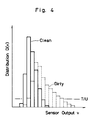
- Figs. 4 and 5 show a second embodiment wherein the detection threshold value is modified with use of the distribution width of a histogram.
- a histogram of sensor output for a clean atmosphere is shown in solid lines, and a histogram of sensor output for a polluted atmosphere in broken lines. These histograms are schematic.
- the feature of the polluted atmosphere is that the histogram has an increased distribution width because the atmosphere is rarely polluted to a constant concentration at all times and because the variations in the concentration of pollutant spread as a wider distribution on the histogram.
- a more accurate detection threshold value can be obtained by modifying the threshold value determined from the modal output, using the distribution width of the histogram.
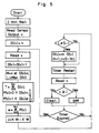
- Fig. 5 shows an operation algorism so adapted.
- the total number of output values, T, on the histogram is calculated, 1 is taken as P(v) when the frequencey D(v) is not smaller than T/U (U is constant), and 0 is taken for P(v) when the frequency is less than T/U.
- the sum w of the values P(v) approximately corresponds to the distribution width of the histogram. Accordingly, the sum w times a constant of X is subtracted from the value K ⁇ M (wherein M is the mode) to obtain a detection threshold value J. In this way, the increase in the threshold value due to the background pollution can be compensated for.
- Fig. 6 shows a circuit diagram of the second embodiment.
- the circuit is substantially the same as the one shown in Fig. 1 except that a different microcomputer 13 is used which comprises a ROM 21 having the constants U and X stored therein, and a RAM 23 for storing the variable T, P(v) and W.
Landscapes
- Chemical & Material Sciences (AREA)
- Life Sciences & Earth Sciences (AREA)
- Engineering & Computer Science (AREA)
- Health & Medical Sciences (AREA)
- Analytical Chemistry (AREA)
- General Physics & Mathematics (AREA)
- Medicinal Chemistry (AREA)
- Physics & Mathematics (AREA)
- Combustion & Propulsion (AREA)
- Biochemistry (AREA)
- General Health & Medical Sciences (AREA)
- Food Science & Technology (AREA)
- Immunology (AREA)
- Pathology (AREA)
- Investigating Or Analyzing Materials By The Use Of Fluid Adsorption Or Reactions (AREA)
- Medicinal Preparation (AREA)
- Orthopedics, Nursing, And Contraception (AREA)
- Investigating Or Analyzing Materials By The Use Of Electric Means (AREA)
Applications Claiming Priority (2)
| Application Number | Priority Date | Filing Date | Title |
|---|---|---|---|
| JP122734/88 | 1988-05-19 | ||
| JP63122734A JP2628341B2 (ja) | 1988-05-19 | 1988-05-19 | ガス検出方法及びその装置 |
Publications (3)
| Publication Number | Publication Date |
|---|---|
| EP0342513A2 EP0342513A2 (en) | 1989-11-23 |
| EP0342513A3 EP0342513A3 (en) | 1990-07-18 |
| EP0342513B1 true EP0342513B1 (en) | 1994-07-06 |
Family
ID=14843267
Family Applications (1)
| Application Number | Title | Priority Date | Filing Date |
|---|---|---|---|
| EP89108443A Expired - Lifetime EP0342513B1 (en) | 1988-05-19 | 1989-05-10 | Gas detecting method and system |
Country Status (4)
| Country | Link |
|---|---|
| US (1) | US5088314A (enExample) |
| EP (1) | EP0342513B1 (enExample) |
| JP (2) | JPS6452461A (enExample) |
| DE (1) | DE68916588T2 (enExample) |
Families Citing this family (31)
| Publication number | Priority date | Publication date | Assignee | Title |
|---|---|---|---|---|
| DE4030516A1 (de) * | 1990-09-27 | 1992-04-02 | Draegerwerk Ag | Verfahren zur konzentrationsueberwachung eines gasfoermigen bestandteils in einem abgeschlossenen raum |
| US5255556A (en) * | 1991-10-15 | 1993-10-26 | Tec-Way Air Quality Products, Inc. | Air quality indicator and control for air quality machine |
| JP2553790B2 (ja) * | 1991-10-18 | 1996-11-13 | 松下精工株式会社 | 換気扇の制御装置 |
| KR930010479A (ko) * | 1991-11-12 | 1993-06-22 | 이헌조 | 자동환기 기능을 갖는 냉/난방 장치 및 그 제어방법 |
| DE4319282C1 (de) * | 1993-06-10 | 1994-09-01 | Daimler Benz Ag | Verfahren zur Erfassung und Auswertung von Abgasen |
| US5386373A (en) * | 1993-08-05 | 1995-01-31 | Pavilion Technologies, Inc. | Virtual continuous emission monitoring system with sensor validation |
| US5428964A (en) * | 1994-01-10 | 1995-07-04 | Tec-Way Air Quality Products Inc. | Control for air quality machine |
| US5394934A (en) * | 1994-04-15 | 1995-03-07 | American Standard Inc. | Indoor air quality sensor and method |
| JPH08313468A (ja) * | 1995-05-24 | 1996-11-29 | Taiyo Toyo Sanso Co Ltd | 過酸化水素蒸気の濃度検出方法及びその装置 |
| US5970426A (en) * | 1995-09-22 | 1999-10-19 | Rosemount Analytical Inc. | Emission monitoring system |
| JPH10340909A (ja) | 1997-06-06 | 1998-12-22 | Hitachi Ltd | 半導体集積回路装置の製造方法 |
| JP3483432B2 (ja) * | 1997-06-18 | 2004-01-06 | 株式会社山武 | 基準値の発生装置 |
| US6273854B1 (en) * | 1998-05-05 | 2001-08-14 | Body Bio Corporation | Medical diagnostic analysis method and system |
| WO2002095740A2 (en) * | 2001-01-09 | 2002-11-28 | Burstein Technologies, Inc. | Methods and apparatus for analyzing operational and nonoperational data acquired from optical discs |
| JPWO2002073697A1 (ja) * | 2001-03-12 | 2004-07-08 | 株式会社ルネサステクノロジ | 半導体集積回路装置およびその製造方法 |
| CN1290197C (zh) * | 2001-03-12 | 2006-12-13 | 株式会社日立制作所 | 用于制造半导体集成电路器件的方法 |
| US20030127105A1 (en) * | 2002-01-05 | 2003-07-10 | Fontana Richard Remo | Complete compact |
| US20040084308A1 (en) * | 2002-11-01 | 2004-05-06 | Cole Barrett E. | Gas sensor |
| US7313966B2 (en) * | 2004-12-14 | 2008-01-01 | Brooks Automation, Inc. | Method and apparatus for storing vacuum gauge calibration parameters and measurement data on a vacuum gauge structure |
| US7421348B2 (en) * | 2005-03-18 | 2008-09-02 | Swanson Brian G | Predictive emissions monitoring method |
| US8768664B2 (en) * | 2005-03-18 | 2014-07-01 | CMC Solutions, LLC. | Predictive emissions monitoring using a statistical hybrid model |
| US20090107157A1 (en) * | 2007-10-25 | 2009-04-30 | Serge Dube | Refrigerant leak-detection systems |
| JP5155027B2 (ja) * | 2008-06-09 | 2013-02-27 | 矢崎エナジーシステム株式会社 | ガス漏れ警報器 |
| JP5185700B2 (ja) * | 2008-06-09 | 2013-04-17 | 矢崎エナジーシステム株式会社 | ガス漏れ警報器 |
| JP5184221B2 (ja) * | 2008-06-09 | 2013-04-17 | 矢崎エナジーシステム株式会社 | ガス漏れ警報器 |
| JP5155026B2 (ja) * | 2008-06-09 | 2013-02-27 | 矢崎エナジーシステム株式会社 | ガス漏れ警報器 |
| DE102012014584A1 (de) * | 2012-07-23 | 2014-01-23 | Hottinger Baldwin Messtechnik Gmbh | Messgrößenaufnehmer mit internem Datenspeicher |
| WO2015048981A1 (en) * | 2013-10-04 | 2015-04-09 | Volvo Truck Corporation | A method for monitoring the operation of a sensor |
| US9879871B2 (en) * | 2014-06-13 | 2018-01-30 | Lennox Industries Inc. | HVAC systems and methods with refrigerant leak detection |
| US10928372B2 (en) * | 2016-01-29 | 2021-02-23 | Ams Sensors Uk Limited | Electronic device |
| US11162928B2 (en) * | 2019-11-04 | 2021-11-02 | Invensense, Inc. | Humidity correction method in thermistor based gas sensing platform |
Family Cites Families (6)
| Publication number | Priority date | Publication date | Assignee | Title |
|---|---|---|---|---|
| DE2924367A1 (de) * | 1979-06-16 | 1980-12-18 | Bayer Ag | Verfahren und vorrichtung zur individuellen ueberwachung der belastung von personen durch schaedliche gase |
| JPS5943327B2 (ja) * | 1980-12-02 | 1984-10-22 | 株式会社デンソー | 車両用空調制御装置 |
| FR2598524B1 (fr) * | 1986-05-07 | 1988-12-02 | Berruyer Yves | Procede de surveillance pour anticiper le declenchement d'une alarme. |
| CH672938A5 (enExample) * | 1986-06-25 | 1990-01-15 | Regez Ag Ofenbau | |
| JPS6383900A (ja) * | 1986-09-29 | 1988-04-14 | ニツタン株式会社 | 環境異常検出器 |
| JP2741381B2 (ja) * | 1988-02-04 | 1998-04-15 | フィガロ技研株式会社 | ガス検出装置 |
-
1988
- 1988-05-19 JP JP63122428A patent/JPS6452461A/ja active Granted
- 1988-05-19 JP JP63122734A patent/JP2628341B2/ja not_active Expired - Fee Related
-
1989
- 1989-05-10 EP EP89108443A patent/EP0342513B1/en not_active Expired - Lifetime
- 1989-05-10 DE DE68916588T patent/DE68916588T2/de not_active Expired - Fee Related
- 1989-05-19 US US07/354,206 patent/US5088314A/en not_active Expired - Fee Related
Also Published As
| Publication number | Publication date |
|---|---|
| JPH01292242A (ja) | 1989-11-24 |
| JP2628341B2 (ja) | 1997-07-09 |
| EP0342513A2 (en) | 1989-11-23 |
| DE68916588D1 (de) | 1994-08-11 |
| JPH0525497B2 (enExample) | 1993-04-13 |
| DE68916588T2 (de) | 1994-10-27 |
| EP0342513A3 (en) | 1990-07-18 |
| JPS6452461A (en) | 1989-02-28 |
| US5088314A (en) | 1992-02-18 |
Similar Documents
| Publication | Publication Date | Title |
|---|---|---|
| EP0342513B1 (en) | Gas detecting method and system | |
| US4532013A (en) | Method for monitoring operation of a current-limiting type gas sensor | |
| JPH0738844Y2 (ja) | 酸素センサ用ヒータ制御装置 | |
| US6649041B2 (en) | Deterioration detector for exhaust gas sensor and method of detecting deterioration | |
| US5517182A (en) | Method for CO detection and its apparatus | |
| US4801211A (en) | Humidity and dew point detector | |
| US4958513A (en) | Gas detecting device | |
| JP2005036743A5 (enExample) | ||
| JP2010086199A (ja) | 警報器 | |
| JP2001349864A (ja) | 排気ガスセンサ用温度検出装置 | |
| KR970022306A (ko) | A/f 센서의 자기진단 방법 및 장치 | |
| US6082177A (en) | Nitric oxide enhanced response circuit for gas analyzer | |
| JP2805048B2 (ja) | ガス検出装置 | |
| US4250737A (en) | Battery powered gas level indicator | |
| JPH11160267A (ja) | 感応膜アレイ型ガス検出器 | |
| KR100363576B1 (ko) | 가스감지방법및이를이용한가스감지장치 | |
| JPH04147048A (ja) | ガス検知装置 | |
| US5672806A (en) | Method and apparatus for calibrating a gas detector sensor | |
| JP2791476B2 (ja) | ガス検出装置 | |
| JP3196943B2 (ja) | ガス検出装置 | |
| JP4094795B2 (ja) | ガス検出器の感度劣化を診断する方法、及び感度劣化診断機能を備えたガス検出器 | |
| JP4294633B2 (ja) | ガス検出装置 | |
| JP2546395B2 (ja) | 酸素センサのヒータ制御故障診断装置 | |
| JPS5839219Y2 (ja) | 自動車用空調制御装置 | |
| CA2247745C (en) | Nitric oxide enhanced response circuit for gas analyzer |
Legal Events
| Date | Code | Title | Description |
|---|---|---|---|
| PUAI | Public reference made under article 153(3) epc to a published international application that has entered the european phase |
Free format text: ORIGINAL CODE: 0009012 |
|
| AK | Designated contracting states |
Kind code of ref document: A2 Designated state(s): AT BE CH DE ES FR GB GR IT LI LU NL SE |
|
| RBV | Designated contracting states (corrected) |
Designated state(s): DE FR GB IT |
|
| PUAL | Search report despatched |
Free format text: ORIGINAL CODE: 0009013 |
|
| AK | Designated contracting states |
Kind code of ref document: A3 Designated state(s): DE FR GB IT |
|
| 17P | Request for examination filed |
Effective date: 19900713 |
|
| 17Q | First examination report despatched |
Effective date: 19920313 |
|
| GRAA | (expected) grant |
Free format text: ORIGINAL CODE: 0009210 |
|
| AK | Designated contracting states |
Kind code of ref document: B1 Designated state(s): DE FR GB IT |
|
| PG25 | Lapsed in a contracting state [announced via postgrant information from national office to epo] |
Ref country code: IT Free format text: LAPSE BECAUSE OF FAILURE TO SUBMIT A TRANSLATION OF THE DESCRIPTION OR TO PAY THE FEE WITHIN THE PRE;WARNING: LAPSES OF ITALIAN PATENTS WITH EFFECTIVE DATE BEFORE 2007 MAY HAVE OCCURRED AT ANY TIME BEFORE 2007. THE CORRECT EFFECTIVE DATE MAY BE DIFFERENT FROM THE ONE RECORDED.SCRIBED TIME-LIMIT Effective date: 19940706 Ref country code: FR Effective date: 19940706 |
|
| REF | Corresponds to: |
Ref document number: 68916588 Country of ref document: DE Date of ref document: 19940811 |
|
| EN | Fr: translation not filed | ||
| PG25 | Lapsed in a contracting state [announced via postgrant information from national office to epo] |
Ref country code: GB Effective date: 19950510 |
|
| PLBE | No opposition filed within time limit |
Free format text: ORIGINAL CODE: 0009261 |
|
| STAA | Information on the status of an ep patent application or granted ep patent |
Free format text: STATUS: NO OPPOSITION FILED WITHIN TIME LIMIT |
|
| 26N | No opposition filed | ||
| GBPC | Gb: european patent ceased through non-payment of renewal fee |
Effective date: 19950510 |
|
| PGFP | Annual fee paid to national office [announced via postgrant information from national office to epo] |
Ref country code: DE Payment date: 20000420 Year of fee payment: 12 |
|
| PG25 | Lapsed in a contracting state [announced via postgrant information from national office to epo] |
Ref country code: DE Free format text: LAPSE BECAUSE OF NON-PAYMENT OF DUE FEES Effective date: 20020301 |