US4250737A - Battery powered gas level indicator - Google Patents
Battery powered gas level indicator Download PDFInfo
- Publication number
- US4250737A US4250737A US06/058,900 US5890079A US4250737A US 4250737 A US4250737 A US 4250737A US 5890079 A US5890079 A US 5890079A US 4250737 A US4250737 A US 4250737A
- Authority
- US
- United States
- Prior art keywords
- indicator
- sensing elements
- sampled
- level indicator
- elements
- Prior art date
- Legal status (The legal status is an assumption and is not a legal conclusion. Google has not performed a legal analysis and makes no representation as to the accuracy of the status listed.)
- Expired - Lifetime
Links
- 239000000523 sample Substances 0.000 claims abstract description 6
- 238000010792 warming Methods 0.000 claims 1
- 239000007789 gas Substances 0.000 description 10
- 239000003990 capacitor Substances 0.000 description 4
- 238000010586 diagram Methods 0.000 description 2
- 231100000572 poisoning Toxicity 0.000 description 2
- 230000000607 poisoning effect Effects 0.000 description 2
- 230000000694 effects Effects 0.000 description 1
- 239000003517 fume Substances 0.000 description 1
Images
Classifications
-
- G—PHYSICS
- G01—MEASURING; TESTING
- G01N—INVESTIGATING OR ANALYSING MATERIALS BY DETERMINING THEIR CHEMICAL OR PHYSICAL PROPERTIES
- G01N27/00—Investigating or analysing materials by the use of electric, electrochemical, or magnetic means
- G01N27/02—Investigating or analysing materials by the use of electric, electrochemical, or magnetic means by investigating impedance
- G01N27/04—Investigating or analysing materials by the use of electric, electrochemical, or magnetic means by investigating impedance by investigating resistance
- G01N27/12—Investigating or analysing materials by the use of electric, electrochemical, or magnetic means by investigating impedance by investigating resistance of a solid body in dependence upon absorption of a fluid; of a solid body in dependence upon reaction with a fluid, for detecting components in the fluid
- G01N27/122—Circuits particularly adapted therefor, e.g. linearising circuits
-
- G—PHYSICS
- G01—MEASURING; TESTING
- G01N—INVESTIGATING OR ANALYSING MATERIALS BY DETERMINING THEIR CHEMICAL OR PHYSICAL PROPERTIES
- G01N33/00—Investigating or analysing materials by specific methods not covered by groups G01N1/00 - G01N31/00
- G01N33/0004—Gaseous mixtures, e.g. polluted air
- G01N33/0009—General constructional details of gas analysers, e.g. portable test equipment
- G01N33/0027—General constructional details of gas analysers, e.g. portable test equipment concerning the detector
- G01N33/0031—General constructional details of gas analysers, e.g. portable test equipment concerning the detector comprising two or more sensors, e.g. a sensor array
Definitions
- This invention relates to a gas level indicator.
- indicators known which are fixed in position to indicate a dangerous increase in gas level in the ambient atmosphere.
- portable quantitative indicators used, for example, to test for leaks on site.
- the present invention relates to the latter type of indicator or detector.
- Such indicators as are known are both expensive and tend to be short-lived.
- existing indicators employ an element which is subject to poisoning and falsification by other gaseous media, for example lead-carrying petrol fumes.
- the invention provides a gas level indicator incorporating two Taguchi-type gas sensing elements, one of which is to receive air to be sampled and the other of which is insulated therefrom, a comparator circuit receiving signals derived from the two elements, and an indicator actuated by the output of the circuit.
- Such an indicator does not suffer the disadvantages of the known portable types, can be battery powered, and provides an accurate reading which eliminates the variables such as ambient pressure, temperature and atmospheric pollution which can otherwise lead to false readings.
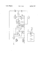
- FIG. 1 shows the circuit diagram of a battery operated gas level indicator
- FIG. 2 is a schematic diagram of a housing for two sensing elements of the indicator.
- a 12 volt battery supply feeds the circuit.
- a regulator 10 is employed. This directly feeds the heaters of two Taguchi-type gas sensing elements 12 and 13. The sensors themselves are in series respectively with resistors 12A, 13A. Two amplifiers 14, 15 receive a fixed proportion of this constant voltage supply, as determined by the voltage divider 16, 17.
- each element 12, 13 the voltage across it is maintained constant by varying the total voltage output by the amplifiers across it and the series resistance 12A, 13A. These outputs are fed by resistors to a third amplifier 18.
- the resultant voltage from the two sensing elements is differentially amplified by this amplifier 18.
- the gain is conveniently set at unity by adjustment of the values of the resistors 20, 21, 22, 23.
- the output of the amplifier drives an analogue meter 25 to indicate gas concentration.
- One of the Taguchi-type gas sensing elements 12, 13 is used to monitor the ambient conditions, while the other element is positioned in air at or from a particular location to be tested, for example, a joint of a gas main.
- the said other element may be housed in a single casing with the rest of the parts of the indicator and supplied with a draught of air through a probe tube.
- FIG. 2 shows such an arrangement with two Taguchi-type sensing elements 12, 13 in a single casing or housing.
- Element 13 is suppied with air to be sampled by means of an elongated pipe 41 and a fan or aspirator element 40.
- the element may be itself housed at the end of a long probe so that it can be introduced into the location to be tested. However, this is a less advantageous arrangement since it carries the risk of a spark from the electrical connections which must be made along the probe to the element.
- the circuit includes a further section designed to prevent a non-zero meter reading until the unit is ready for action, i.e., until the sensor heaters have warmed up.
- a capacitor 31 is charged via a resistor 32 and discharged via a diode 33 when the unit is switched off.
- the level of voltage across the capacitor is monitored relative to a voltage divider 34, 35 by a further amplifier 36.
- the output of this amplifier is high when the voltage across the capacitor is low. This high voltage is applied via a diode 37 to the amplifier 18, and thus keeps its output voltage low.
- the output of the amplifier 36 changes from high to low. This reverse biases the diode 37, allowing the amplifier 18 to operate normally, and at the same time provides an indication that the meter reading can be trusted by illuminating a light emitting diode 38.
- the analogue meter may if required be replaced by a simple on/off indicator.
Landscapes
- Chemical & Material Sciences (AREA)
- Health & Medical Sciences (AREA)
- Life Sciences & Earth Sciences (AREA)
- General Health & Medical Sciences (AREA)
- Immunology (AREA)
- Engineering & Computer Science (AREA)
- Analytical Chemistry (AREA)
- Biochemistry (AREA)
- Pathology (AREA)
- General Physics & Mathematics (AREA)
- Physics & Mathematics (AREA)
- Chemical Kinetics & Catalysis (AREA)
- Electrochemistry (AREA)
- Combustion & Propulsion (AREA)
- Food Science & Technology (AREA)
- Medicinal Chemistry (AREA)
- Sampling And Sample Adjustment (AREA)
- Investigating Or Analyzing Materials By The Use Of Electric Means (AREA)
Abstract
A gas level indicator incorporates two Taguchi-type sensing elements, one of which is to receive air to be sampled and the other of which is insulated therefrom. A comparator circuit receives the outputs of the two elements, and an indicator actuated by the output of the circuit announces the result of the comparison. Preferably, both sensing elements are mounted in a single housing, and an elongated pipe and a fan or aspirator provided to form a probe for drawing air to be sampled from a remote position to the one element.
Description
This invention relates to a gas level indicator. There are indicators known which are fixed in position to indicate a dangerous increase in gas level in the ambient atmosphere. There are also portable quantitative indicators used, for example, to test for leaks on site. The present invention relates to the latter type of indicator or detector.
Such indicators as are known are both expensive and tend to be short-lived. In particular, existing indicators employ an element which is subject to poisoning and falsification by other gaseous media, for example lead-carrying petrol fumes.
It is an object of the invention to provide a portable indicator, preferably battery-powered, which is cheap, has a relatively long life, and is not subject to poisoning of the detector element.
Accordingly, the invention provides a gas level indicator incorporating two Taguchi-type gas sensing elements, one of which is to receive air to be sampled and the other of which is insulated therefrom, a comparator circuit receiving signals derived from the two elements, and an indicator actuated by the output of the circuit.
Such an indicator does not suffer the disadvantages of the known portable types, can be battery powered, and provides an accurate reading which eliminates the variables such as ambient pressure, temperature and atmospheric pollution which can otherwise lead to false readings.
In order that the invention shall be clearly understood, an exemplary embodiment thereof will now be described with reference to the accompanying drawings, of which:
FIG. 1 shows the circuit diagram of a battery operated gas level indicator; and
FIG. 2 is a schematic diagram of a housing for two sensing elements of the indicator.
Referring now to the drawings, in the embodiment of FIG. 1 a 12 volt battery supply feeds the circuit. In order to provide a stable voltage for the detector circuits, a regulator 10 is employed. This directly feeds the heaters of two Taguchi-type gas sensing elements 12 and 13. The sensors themselves are in series respectively with resistors 12A, 13A. Two amplifiers 14, 15 receive a fixed proportion of this constant voltage supply, as determined by the voltage divider 16, 17.
Despite the changing resistance of each element 12, 13 the voltage across it is maintained constant by varying the total voltage output by the amplifiers across it and the series resistance 12A, 13A. These outputs are fed by resistors to a third amplifier 18. The resultant voltage from the two sensing elements is differentially amplified by this amplifier 18. The gain is conveniently set at unity by adjustment of the values of the resistors 20, 21, 22, 23. The output of the amplifier drives an analogue meter 25 to indicate gas concentration.
One of the Taguchi-type gas sensing elements 12, 13 is used to monitor the ambient conditions, while the other element is positioned in air at or from a particular location to be tested, for example, a joint of a gas main. The said other element may be housed in a single casing with the rest of the parts of the indicator and supplied with a draught of air through a probe tube. FIG. 2 shows such an arrangement with two Taguchi- type sensing elements 12, 13 in a single casing or housing. Element 13 is suppied with air to be sampled by means of an elongated pipe 41 and a fan or aspirator element 40. Alternatively, the element may be itself housed at the end of a long probe so that it can be introduced into the location to be tested. However, this is a less advantageous arrangement since it carries the risk of a spark from the electrical connections which must be made along the probe to the element.
In either case, the effects of temperature, of humidity and of other gas contaminents are equalised for both probes, and a comparison can be made between the ambient situation and that at a particular narrow location required to be tested.
The circuit includes a further section designed to prevent a non-zero meter reading until the unit is ready for action, i.e., until the sensor heaters have warmed up. A capacitor 31 is charged via a resistor 32 and discharged via a diode 33 when the unit is switched off. The level of voltage across the capacitor is monitored relative to a voltage divider 34, 35 by a further amplifier 36. The output of this amplifier is high when the voltage across the capacitor is low. This high voltage is applied via a diode 37 to the amplifier 18, and thus keeps its output voltage low.
When the voltage across the capacitor 31 exceeds the voltage tapped, the output of the amplifier 36 changes from high to low. This reverse biases the diode 37, allowing the amplifier 18 to operate normally, and at the same time provides an indication that the meter reading can be trusted by illuminating a light emitting diode 38.
The analogue meter may if required be replaced by a simple on/off indicator.
Claims (4)
1. A gas level indicator incorporating two Taguchi-type gas sensing elements, one of which is to receive air to be sampled and the other of which is insulated therefrom, a comparator circuit receiving signals derived from the two elements, and an indicator actuated by the output of the circuit, wherein each sensing element is connected in series with a resistor, two amplifiers respectively supply a voltage across the element and its series resistor, and said voltage is in each case varied to maintain constant the partial voltage across the element alone, said voltage forming said signal in each case.
2. A gas level indicator incorporating two Taguchi-type gas sensing elements, one of which is to receive air to be sampled and the other of which is insulated therefrom, a comparator circuit receiving signals derived from the two elements, and an indicator actuated by the output of the circuit, wherein both sensing elements are mounted in a single housing, and an elongated pipe and a fan or aspirator are provided to form a probe for drawing air to be sampled to the one element.
3. A gas level indicator incorporating two Taguchi-type gas sensing elements, one of which is to receive air to be sampled and the other of which is insulated therefrom, a comparator circuit receiving signals derived from the two elements, and an indicator actuated by the output of the circuit, wherein a delay circuit is connected so as to block the output of the comparator circuit for an initial period after switching on matched to the warming up period of the sensing elements.
4. A gas level indicator as claimed in claim 3 wherein an indicator is included in the delay circuit which shows when said initial period has elapsed.
Applications Claiming Priority (2)
| Application Number | Priority Date | Filing Date | Title |
|---|---|---|---|
| GB30325/78 | 1978-07-19 | ||
| GB7830325A GB2048487A (en) | 1978-07-19 | 1978-07-19 | Battery powered gas level indicator |
Publications (1)
| Publication Number | Publication Date |
|---|---|
| US4250737A true US4250737A (en) | 1981-02-17 |
Family
ID=10498510
Family Applications (1)
| Application Number | Title | Priority Date | Filing Date |
|---|---|---|---|
| US06/058,900 Expired - Lifetime US4250737A (en) | 1978-07-19 | 1979-07-19 | Battery powered gas level indicator |
Country Status (3)
| Country | Link |
|---|---|
| US (1) | US4250737A (en) |
| GB (1) | GB2048487A (en) |
| ZA (1) | ZA793685B (en) |
Cited By (9)
| Publication number | Priority date | Publication date | Assignee | Title |
|---|---|---|---|---|
| FR2514898A1 (en) * | 1981-10-16 | 1983-04-22 | Armines | METHOD, SENSOR AND DEVICE FOR DETECTING TRACES OR GASEOUS IMPURITIES |
| US4414839A (en) * | 1979-04-12 | 1983-11-15 | Board Of Trustees, A Constitutional Corporation Operating Michigan State University | Gas sensing apparatus and method |
| US4644333A (en) * | 1983-10-14 | 1987-02-17 | Statt der Nederlanden (Stattsbedrijf der Rosterijen, Telegrafie en Telefonie) | Gas sensor and detection system comprising such a sensor |
| US4868546A (en) * | 1984-10-03 | 1989-09-19 | Dumbeck Robert F | Radon detector |
| US5447054A (en) * | 1990-03-02 | 1995-09-05 | Eniricerche S.P.A. | Gas sensors formed of thin tin oxide films, for gaseous hydro-carbon determination |
| WO1995032422A1 (en) * | 1994-05-23 | 1995-11-30 | Aromascan Plc | Sensor |
| US5780715A (en) * | 1996-10-23 | 1998-07-14 | Mine Safety Appliances Company | Combustible gas measuring sensor circuit |
| US20050223774A1 (en) * | 2004-04-07 | 2005-10-13 | Drager Safety Ag & Co. Kgaa | Breath alcohol measuring device |
| WO2018169996A1 (en) * | 2017-03-13 | 2018-09-20 | University Of Houston System | A method for directly measuring so2 and other trace gases by electrochemical cell (ecc) sonde |
Citations (2)
| Publication number | Priority date | Publication date | Assignee | Title |
|---|---|---|---|---|
| DE2313413A1 (en) * | 1973-03-17 | 1974-09-26 | Westfaelische Berggewerkschaft | Carbon monoxide detection using semiconductors - with temp variation giving long term stability and methane detection |
| US4147513A (en) * | 1977-09-26 | 1979-04-03 | Bendix Autolite Corporation | Method and apparatus for measuring the O2 content of a gas |
-
1978
- 1978-07-19 GB GB7830325A patent/GB2048487A/en not_active Withdrawn
-
1979
- 1979-07-19 US US06/058,900 patent/US4250737A/en not_active Expired - Lifetime
- 1979-07-19 ZA ZA00793685A patent/ZA793685B/en unknown
Patent Citations (2)
| Publication number | Priority date | Publication date | Assignee | Title |
|---|---|---|---|---|
| DE2313413A1 (en) * | 1973-03-17 | 1974-09-26 | Westfaelische Berggewerkschaft | Carbon monoxide detection using semiconductors - with temp variation giving long term stability and methane detection |
| US4147513A (en) * | 1977-09-26 | 1979-04-03 | Bendix Autolite Corporation | Method and apparatus for measuring the O2 content of a gas |
Cited By (13)
| Publication number | Priority date | Publication date | Assignee | Title |
|---|---|---|---|---|
| US4414839A (en) * | 1979-04-12 | 1983-11-15 | Board Of Trustees, A Constitutional Corporation Operating Michigan State University | Gas sensing apparatus and method |
| FR2514898A1 (en) * | 1981-10-16 | 1983-04-22 | Armines | METHOD, SENSOR AND DEVICE FOR DETECTING TRACES OR GASEOUS IMPURITIES |
| EP0077724A1 (en) * | 1981-10-16 | 1983-04-27 | Association Pour La Recherche Et Le Developpement Des Methodes Et Processus Industriels (Armines) | Method, sensor and apparatus for detecting traces of gas in a gaseous medium |
| US4485667A (en) * | 1981-10-16 | 1984-12-04 | Association pour la Recherche et la Developpement des Methodes et Processus Industriels (Armines) | Method, sensor and device for detecting trace quantities of gases in a gaseous medium |
| US4644333A (en) * | 1983-10-14 | 1987-02-17 | Statt der Nederlanden (Stattsbedrijf der Rosterijen, Telegrafie en Telefonie) | Gas sensor and detection system comprising such a sensor |
| US4868546A (en) * | 1984-10-03 | 1989-09-19 | Dumbeck Robert F | Radon detector |
| US5447054A (en) * | 1990-03-02 | 1995-09-05 | Eniricerche S.P.A. | Gas sensors formed of thin tin oxide films, for gaseous hydro-carbon determination |
| WO1995032422A1 (en) * | 1994-05-23 | 1995-11-30 | Aromascan Plc | Sensor |
| US5780715A (en) * | 1996-10-23 | 1998-07-14 | Mine Safety Appliances Company | Combustible gas measuring sensor circuit |
| US20050223774A1 (en) * | 2004-04-07 | 2005-10-13 | Drager Safety Ag & Co. Kgaa | Breath alcohol measuring device |
| US7171842B2 (en) * | 2004-04-07 | 2007-02-06 | Dräger Safety AG & Co., KGaA | Breath alcohol measuring device |
| WO2018169996A1 (en) * | 2017-03-13 | 2018-09-20 | University Of Houston System | A method for directly measuring so2 and other trace gases by electrochemical cell (ecc) sonde |
| US11150217B2 (en) | 2017-03-13 | 2021-10-19 | University Of Houston System | Method for directly measuring SO2 and other trace gases by electrochemical cell (ECC) sonde |
Also Published As
| Publication number | Publication date |
|---|---|
| ZA793685B (en) | 1980-07-30 |
| GB2048487A (en) | 1980-12-10 |
Similar Documents
| Publication | Publication Date | Title |
|---|---|---|
| US4443791A (en) | Self-compensating gas detection apparatus | |
| US6489787B1 (en) | Gas detection circuit | |
| US4537068A (en) | Thermal anemometer | |
| US8590363B2 (en) | Personal breathalyzer having digital circuitry | |
| US3950739A (en) | Detector for detecting and locating the source of a contaminating gas or smoke in the atmosphere | |
| US4817414A (en) | Measuring arrangement for detecting the level of combustible gases mixed with air | |
| US4028057A (en) | Gas analyzer | |
| US5218347A (en) | Apparatus for detecting hazardous gases | |
| US4250737A (en) | Battery powered gas level indicator | |
| EP0314919B1 (en) | Combustible gas detector having temperature stabilization capability | |
| WO2007134042A1 (en) | Personal breathalyzer | |
| US5305231A (en) | Multiple K factor, selectable gas detector | |
| US4166380A (en) | Quantitative measuring system for combustible gas with audible tick rate | |
| US3375700A (en) | Portable gas analyzer for testing subterranean ambient air samples | |
| US5744938A (en) | Method and apparatus for testing a vehicle charge storage system | |
| EP0432962B1 (en) | Flammable gas detection | |
| US4476096A (en) | Circuit arrangement for an apparatus for measuring and indicating the concentration of combustible gases and vapors contained in air | |
| GB1581401A (en) | Apparatus for measuring the alcohol percentage in the breath of an examiner | |
| KR940022073A (en) | Gas sensor characteristic measuring device | |
| US4078179A (en) | Movable instrument with light emitting position indicator | |
| US4155245A (en) | Dewpointmeters | |
| EP0268649A1 (en) | Breath alcohol or drug detecting device | |
| WO1983004101A1 (en) | Oxygen analyzer | |
| FR2462704A1 (en) | GAS SENSOR POWERED BY A BATTERY | |
| US3370457A (en) | Gas detector |