US6489787B1 - Gas detection circuit - Google Patents
Gas detection circuit Download PDFInfo
- Publication number
- US6489787B1 US6489787B1 US09/689,990 US68999000A US6489787B1 US 6489787 B1 US6489787 B1 US 6489787B1 US 68999000 A US68999000 A US 68999000A US 6489787 B1 US6489787 B1 US 6489787B1
- Authority
- US
- United States
- Prior art keywords
- wheatstone bridge
- bridge circuit
- fixed resistor
- natural gas
- output signal
- Prior art date
- Legal status (The legal status is an assumption and is not a legal conclusion. Google has not performed a legal analysis and makes no representation as to the accuracy of the status listed.)
- Expired - Lifetime, expires
Links
Images


Classifications
-
- G—PHYSICS
- G01—MEASURING; TESTING
- G01N—INVESTIGATING OR ANALYSING MATERIALS BY DETERMINING THEIR CHEMICAL OR PHYSICAL PROPERTIES
- G01N27/00—Investigating or analysing materials by the use of electric, electrochemical, or magnetic means
- G01N27/02—Investigating or analysing materials by the use of electric, electrochemical, or magnetic means by investigating impedance
- G01N27/04—Investigating or analysing materials by the use of electric, electrochemical, or magnetic means by investigating impedance by investigating resistance
- G01N27/14—Investigating or analysing materials by the use of electric, electrochemical, or magnetic means by investigating impedance by investigating resistance of an electrically-heated body in dependence upon change of temperature
- G01N27/18—Investigating or analysing materials by the use of electric, electrochemical, or magnetic means by investigating impedance by investigating resistance of an electrically-heated body in dependence upon change of temperature caused by changes in the thermal conductivity of a surrounding material to be tested
- G01N27/185—Investigating or analysing materials by the use of electric, electrochemical, or magnetic means by investigating impedance by investigating resistance of an electrically-heated body in dependence upon change of temperature caused by changes in the thermal conductivity of a surrounding material to be tested using a catharometer
-
- G—PHYSICS
- G01—MEASURING; TESTING
- G01N—INVESTIGATING OR ANALYSING MATERIALS BY DETERMINING THEIR CHEMICAL OR PHYSICAL PROPERTIES
- G01N27/00—Investigating or analysing materials by the use of electric, electrochemical, or magnetic means
- G01N27/02—Investigating or analysing materials by the use of electric, electrochemical, or magnetic means by investigating impedance
- G01N27/04—Investigating or analysing materials by the use of electric, electrochemical, or magnetic means by investigating impedance by investigating resistance
- G01N27/14—Investigating or analysing materials by the use of electric, electrochemical, or magnetic means by investigating impedance by investigating resistance of an electrically-heated body in dependence upon change of temperature
- G01N27/16—Investigating or analysing materials by the use of electric, electrochemical, or magnetic means by investigating impedance by investigating resistance of an electrically-heated body in dependence upon change of temperature caused by burning or catalytic oxidation of surrounding material to be tested, e.g. of gas
Definitions
- the present invention relates to a method for detecting gas leaks. More particularly, the present invention is directed to an electronic circuit that can detect natural gas at any level.
- Natural gas detection at part per million concentrations is required to locate leaks in piping and around equipment connections. Higher levels of natural gas can lead to explosive reaction. The concentration of natural gas can build to such levels over time if a leak occurs in an enclosed area. For this reason, it is necessary to measure natural gas in enclosed areas where leakage can occur and concentrations may build to levels capable of explosive reaction in order to provide warning of an explosive hazard. Natural gas concentrations beyond the explosive range can be caused by leakage into small closed volumes, such as around a buried gas pipe or in regulator pits. Natural gas concentration readings in these instances may be used to precisely locate leaks, thereby reducing the cost to repair lines by limiting the excavation necessary to expose the leaking section.
- the preferred natural gas detection method can vary depending on the concentration of natural gas anticipated. For example, if part per million or explosive concentrations of natural gas are anticipated, a catalytic detector can be used. For natural gas concentrations beyond the explosive range, a detector based on thermal conductivity methods of measurement may be used.
- catalytic gas detectors examples include U.S. Pat. No. 3,678,489 to Scherban et al.; U.S. Pat. No. 4,164,699 to Timoshenko et al.; U.S. Pat. No. 4,375,353 to Nicholas et al.; and U.S. Pat. No. 5,563,578 to Isenstein.
- U.S. Pat. No. 5,586,050 to Makel et al. discloses the use of a catalytic gas detector from Det-Tronics, Minneapolis, Minnesota. Examples of Det-Tronics detectors are Det-Tronics Model 226530-01 and CGS Detector.
- Catalytic detectors typically react to a combustible gas which may come from a variety of sources with oxygen from the surrounding air.
- the reaction between combustible vapors and air is promoted by the catalytic material on the surface of one of two elements.
- the elements are electrically and thermally matched, temperature sensitive, resistive elements.
- the combustion reaction on the catalytically-coated element releases heat, raising the temperature of that element and, therefore, its resistance, with respect to the matching element which is not catalytically coated.
- This resistive imbalance is measured in a Wheatstone bridge circuit with the signal output derived being connected to additional electrical components to perform a variety of functions.
- U.S. Pat. No. 5,055,269 to Palumbo et al. discloses this type of detector.
- Another type of gas leak detector used to detect high concentration gas leaks is based on an acoustic detection system where microphones are used to “listen” for the sound of gas leaking from a pipe, fitting, or valve.
- acoustic methods are disclosed in U.S. Pat. No. 5,117,676 to Chang; U.S. Pat. No. 5,416,724 to Savic; and U.S. Pat. No. 5,650,943 to Powell et al. These methods have a drawback in that in order for a leak to be audible, it must be significant. Therefore, early detection is not provided.
- Still another method for detecting natural gas is described in U.S. Pat. No. 4,013,943 to Chou et al.
- This method involves a solid state electrolytic cell sensor that causes the dissociation of the gas into charged species, such as ions and complex ions.
- This method also utilizes a heater, which can be dangerous and is limited as to how low the detection limit for natural gas can be.
- the present invention is directed to a unique circuit capable of detecting natural gas at a wide range of concentrations.
- the gas detection circuit includes a catalytic Wheatstone bridge circuit and an analyzing Wheatstone bridge circuit.
- the catalytic Wheatstone bridge circuit includes an active element and a reference element on a first half of the catalytic Wheatstone bridge circuit and a first fixed resistor and a second fixed resistor on a second half of the catalytic Wheatstone bridge circuit.
- the analyzing Wheatstone bridge circuit includes the active element and the reference element in series, acting as a single element in series with a third fixed resistor on a first half of the analyzing Wheatstone bridge circuit.
- a second half of the analyzing Wheatstone bridge circuit includes a fourth fixed resistor and a fifth fixed resistor, which balance the first half of the analyzing Wheatstone bridge circuit.
- the catalytic Wheatstone bridge circuit and analyzing Wheatstone bridge circuit are powered by maintaining a fixed voltage difference across the respective Wheatstone bridge circuits.
- An output signal is taken from the midpoint of the half bridge at the juncture of the active element and the reference element for comparison to the voltage at the midpoint of the two matched balancing resistors, which are the first fixed resistor and the second fixed resistor.
- the intensity of the signal is proportional to the concentration of natural gas.
- the present invention is also directed to a method of detecting natural gas.
- the method includes placing a device containing the circuit described above in an area in which the air has a potential of containing natural gas and monitoring the output signal for indications of the presence of natural gas.
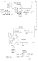
- FIG. 1 is a schematic diagram of the gas detection circuit of the present invention.
- FIGS. 2 a, 2 b, and 2 c are a schematic diagram of an embodiment of the gas detection circuit of the present invention.
- a gas detection circuit 8 of the present invention includes a catalytic Wheatstone bridge circuit 10 and an analyzing Wheatstone bridge circuit 12 .
- the catalytic Wheatstone bridge circuit 10 includes an active element 14 and a reference element 16 on a first half 18 of the catalytic Wheatstone bridge circuit 10 and a first fixed resistor 20 and a second fixed resistor 22 on a second half 24 of the catalytic Wheatstone bridge circuit 10 .
- the analyzing Wheatstone bridge circuit 12 includes the active element 14 and the reference element 16 in series, acting as a single element in series with a third fixed resistor 26 on a first half 28 of the analyzing Wheatstone bridge circuit 12 .
- a second half 30 of the analyzing Wheatstone bridge circuit 12 includes a fourth fixed resistor 34 and a fifth fixed resistor 36 , which balance the first half 28 of the analyzing Wheatstone bridge circuit 12 .
- the catalytic Wheatstone bridge circuit 10 is powered by a fixed voltage regulator 42 , which maintains a fixed voltage difference across catalytic Wheatstone bridge circuit 10 .
- a first output signal 38 is taken from the midpoint of a first half 18 of catalytic Wheatstone bridge circuit 10 at a first juncture 44 of active element 14 and reference element 16 for comparison to the voltage at the midpoint of a second half 24 of catalytic Wheatstone bridge circuit 10 taken from the midpoint of the two matched balancing resistors, which is a second juncture 46 located between first fixed resistor 20 and second fixed resistor 22 .
- analyzing Wheatstone bridge circuit 12 which acts as a thermal conductivity Wheatstone bridge circuit, is used.
- Fixed voltage regulator 42 provides power, which is regulated voltage controlled to maintain a fixed voltage difference across the matched elements of analyzing Wheatstone bridge circuit 12 .
- the voltage is applied to third fixed resistor 26 connected in series with active element 14 and reference element 16 and to series connected fourth fixed resistor 34 and fifth fixed resistor 36 .
- Fourth fixed resistor 34 and fifth fixed resistor 36 are connected in parallel with third fixed resistor 26 , active element 14 , and reference element 16 .
- Third fixed resistor 26 becomes a current-sensing resistor in conjunction with the fixed voltage maintained across sensing elements, active element 14 , and reference element 16 , allowing determination of the resistance of active element 14 and reference element 16 .
- a second signal output 45 is taken from a third juncture 48 located between third fixed resistor 26 and active element 14 and from a fourth juncture 50 located between fourth fixed resistor 34 and fifth fixed resistor 36 .
- the thermal conductivity detector analyzing Wheatstone bridge circuit 12 , operates on the well-recognized principle that a heated element exposed to gasses with different thermal conductivities will vary in resistance with the relative concentrations of the gas mixture to which it is exposed. By measuring the resistance of the two matched elements in comparison to the series fixed resistor, a signal may be derived which is proportional to the concentration of methane (natural gas is 90% or higher methane) in air over the full range of concentration from 0 to 100% by volume.
- the power requirement is determined by a regulator and switching circuit 55 , which is external to analyzing Wheatstone bridge circuit 12 and catalytic Wheatstone bridge circuit 10 .
- Regulator and switching circuit 55 includes the fixed voltage regulator 42 , which controls voltage V out , a voltage sensing circuit 56 , a first range control switch 58 , and a second range control switch 60 .
- Voltage sensing circuit 56 includes a sixth fixed resistor 52 and a seventh fixed resistor 54 connected in parallel with the catalytic detector elements, active element 14 and reference element 16 .
- First range control switch 58 is externally controlled and capable of shorting out sixth fixed resistor 52 in the high gas concentration range. This increases the sensed voltage applied to catalytic Wheatstone bridge circuit 10 when the sensed voltage is reduced by the ratio of the resistance of sixth fixed resistor 52 to the resistance of seventh fixed resistor 54 .
- Second range control switch 60 controls selection of the point to which the voltage is applied, bypassing third fixed resistor 26 for the catalytic Wheatstone bridge circuit 10 , and including third fixed resistor 26 in the circuit for the thermal conductivity bridge circuit, analyzing Wheatstone bridge circuit 12 .
- LEL lower explosive limit
- the catalytic detector voltage is about one-half of the voltage supplied for catalytic operation. The change in detector voltage prevents the detector from catalytically-reacting methane, which requires a high operating voltage in comparison to most other hydrocarbon vapors for catalytic reaction.
- the power supplied by fixed voltage regulator 42 maintains a fixed voltage across the catalytic detector elements, active element 14 and reference element 16 , using current sensing third fixed resistor 26 to measure changes in resistance of the catalytic detector elements.
- This method of power control results in second output signal 45 , which is much more linear than either voltage or current regulation of analyzing Wheatstone bridge circuit 12 .
- voltage or current regulation of analyzing Wheatstone bridge circuit 12 could also be used within the scope of the present invention to provide a similar operation if suitable correction for linearity were made by other devices.
- reference element 16 and active element 14 are cooled by increasing concentrations of methane, lowering their resistance.
- the output signal 44 used to determine concentration is the total resistance (voltage) of elements 14 and 16 in series, providing an enhanced signal level for improved accuracy. Since elements 14 and 16 of the catalytic detector are temperature sensitive, and the current sensing resistor (third fixed resistor 26 ) is not, it is necessary to correct the offset (zero) using the temperature of the block in which the elements are mounted. The temperature is measured by thermocouple 62 , which provides a temperature output signal 63 . A microprocessor (not shown) is used to combine both output signals 38 and 45 with temperature output signal 63 to calculate temperature-adjusted output signals. It is possible to thermally match third fixed resistor 26 to the detector characteristics in order to eliminate the offset correction, however, this would result in a more expensive and complex detector assembly.
- the concept of the thermal conductivity analysis is to reduce the catalyst temperature on the detector to below the temperature at which a methane/air reaction will occur. Measurement at such a temperature is possible since methane is the most stable hydrocarbon and the most difficult to react requiring a high catalyst temperature. Propane is more easily reacted by the catalyst, allowing reaction at a lower temperature or detection voltage.
- active (catalyzed) element 14 and reference (non-catalyzed) element 16 separately, it is possible to detect a difference in element temperature which would not exist if propane were not present.
- This first output signal 38 provides a fault indication, improving the reliability of the test method.
- One embodiment of the gas detection circuit of the present invention uses a detector assembly part number 4P-100 from City Technology Ltd., Portsmouth, England, which includes both the active element 14 as well as balancing reference element 16 in a sealed assembly.
- the circuit with appropriate choice of related elements, will work with any compensated, matched catalytic detector. Normal operating voltage for this detector, when operating in the catalytic detection mode, is 3.0 Volts. The electrical current is approximately 90 ma resulting in a resistance of 30 Ohms at this voltage.
- Elements first fixed resistor 20 and second fixed resistor 22 are fixed, metal film resistors reasonably matched to allow the output to be balanced by the electronic circuits (for example, 1% resistors).
- the resistors would usually be chosen to have as high a value as possible for reduced operating power, they must be of low enough value not to load the output device, in this case an operational amplifier.
- Voltage is regulated by a solid state circuit, which could be, for example, an operational amplifier driving a power transistor to control output voltage. Equally acceptable is an integrated circuit adjustable linear regulator, or a switching regulator circuit, for reduced power loss.
- the regulated voltage must pass through second range control switch 60 , which, in the embodiment chosen, is a field effect transistor (FET) chosen for low on resistance.
- FET field effect transistor
- the FET is turned off (second range control switch 60 opened) so power flows through third fixed resistor 26 , to active element 14 and reference element 16 and first fixed resistor 20 , and second fixed resistor 22 to ground.
- Active element 14 , reference element 16 , first fixed resistor 20 and second fixed resistor 22 act as a single, temperature sensitive resistance matched by third fixed resistor 26 to form one-half of a Wheatstone bridge circuit.
- the balancing resistors in the bridge are fourth fixed resistor 34 and fifth fixed resistor 36 .
- Third fixed resistor 26 is sized to match the resistance of the four elements, active element 14 , reference element 16 , first fixed resistor 20 , and second fixed resistor 22 , operating at a voltage nominally one-half of the voltage used for catalytic operation (1.5 Volts in this case).
- the resistance of the detector elements at the reduced voltage is approximately 20 Ohms, and third fixed resistor 26 was chosen to meet this value.
- the scheme used in this embodiment is a pulse width modulated signal from the microprocessor, which is fed to the reference input of an operational amplifier whose output is applied to the inputs of the signal amplifiers through a suitable resistor network.
- This scheme allows a variable offset which can be varied, by varying the pulse width at the startup of the instrument, until the bridge offset is within allowable limits, which allows proper operation of the A/D converter.
- the detection circuit operates in two distinctly different modes: (1) a lower range mode going to but not exceeding 100% of the lower explosive limit (LEL) of methane or 5% by volume, depending on how the display is chosen and (2) a higher concentration range going to 100% by volume of methane starting at any concentration up to 5% by volume.
- LEL lower explosive limit
- the lower range (1) operates on the catalytic detection method, which is well known in the art and uses standard design catalytic detectors readily available from a variety of sources.
- the higher concentration range (2) uses the basic thermal conductivity method of detection employing a novel method of using a standard catalytic detector as the sensing element. The range is selected automatically by the microprocessor. The higher range is less accurate at lower concentrations of natural gas than the lower range.
- the catalytic detector In the lower range, the catalytic detector is used with fixed resistors in a Wheatstone bridge configuration with a regulated voltage excitation.
- the outputs are caused as the catalytic element reacts with methane, increasing the temperature and resistance with respect to the reference element.
- the bridge circuit as a result, becomes unbalanced, which provides an output that is linear with respect to the percentage of the LEL up to 100% of the LEL.
- This electrical signal may be applied to the input to an operational amplifier whose output feeds into an A/D converter, which is subsequently sent in digital format to the microprocessor.
- the output would go to a display device, such as a liquid crystal display (LCD), and to alarm indicators, such as a light emitting diode (LED), and/or audible devices, relays, etc.
- a display device such as a liquid crystal display (LCD)
- alarm indicators such as a light emitting diode (LED), and/or audible devices, relays, etc.
- Information on detector gain and alarm levels is stored in microprocessor memory.
- the high range would be selected automatically by the microprocessor when the low range has been exceeded. Again, the output signal is applied as an input to an operational amplifier and then to an A/D converter and the microprocessor input. The information is again applied to a digital display as a convenience. A bar graph may be used to track the concentration levels and also to retain the highest reading. Alarms are not usually used in the high gas range.
- a standard catalytic detector bridge 100 with an active element 104 and a reference element 102 , is used for detection, and a first balancing resistor R 10 and a second balancing resistor R 11 are balancing resistors in a standard Wheatstone bridge configuration.
- Power is supplied as an excitation voltage CAT_EXCIT, via a low drop out adjustable voltage regulator U 19 .
- Adjustable voltage regulator U 19 is programmed via a resistor digital-to-analog converter (DAC) U 5 using an analog output signal CAT_REF.
- DAC digital-to-analog converter
- Resistor DAC U 5 is controlled by a first digital input P 17 S from first microprocessor port P 17 and a second digital input P 31 S from second microprocessor port P 31 , which provides a command to control the value of the resistance of resistor DAC U 5 .
- the resistance of resistor DAC U 5 provides an analog output signal CAT_REF.
- the excitation current to catalytic detector bridge 100 passes through a current sensing resistor R 2 .
- Catalytic detector bridge 100 provides a first bridge signal CAT_MIDLO+ and a second bridge signal CAT_MIDLO ⁇ , which are sent to a digital multiplexer U 2 .
- Digital multiplexer U 2 sequentially sends the input signals to an A/D CONVERTER U 4 , which digitizes the analog signals and transfers them to a third microprocessor port P 30 as a third input signal P 30 S.
- the third input signal could be transmitted to a microcomputer, minicomputer, or a computer.
- Digital multiplexer U 2 also receives a first input signal CAT_HI+, which is the input to current sensing resistor R 2 and second input signal CAT_HI ⁇ , which is the output from current sensing resistor R 2 . Digital multiplexer U 2 also receives a voltage signal TEMP, which is proportional to the temperature of catalytic detector bridge 100 and is referenced to ground.
- a voltage is applied to catalytic detector bridge 100 , which is sufficient to cause a reaction between air and methane gas, releasing heat, which raises the temperature of active element 104 of catalytic detector bridge 100 , resulting in an unbalance between first input signal CAT_MIDLO+ and second input signal CAT_MIDLO ⁇ , which is proportional to the concentration of methane at low-volume concentrations.
- first input signal CAT_MIDLO+ and second input signal CAT_MIDLO ⁇ which is proportional to the concentration of methane at low-volume concentrations.
- the determination of methane concentration based on first input signal CAT_HI+ and second input signal CAT_HI ⁇ may become unreliable. Exposure above the LEL may damage the detector.
- excitation voltage CAT_EXCITE is reduced by changing analog output signal CAT_REF.
- the excitation voltage CAT_EXCITE is reduced sufficiently in that catalytic detection bridge 100 will no longer react to methane and air.
- digital multiplexer U 2 sends first input signal CAT_HI+ and second input signal CAT_HI ⁇ from current sensing resistor R 2 to A/D CONVERTER U 4 , rather than first bridge signal CAT_MIDLO+ and second bridge signal CAT_MIDLO ⁇ from catalytic detector bridge 100 .
- the current sensing resistor circuit allows a direct measurement of the resistance of the sensor bridge circuit, which changes in direct proportion to the concentration of methane, since methane has a higher thermal conductivity than air.
- an initial resistance In order to use the change in resistance of the detector bridge to measure high concentrations of methane, an initial resistance must be determined and stored by a microprocessor at start up, using air without methane as a basis. A similar activity is performed on the low-range methane reading. When the detector switches to the high range, this stored value is used as a baseline or zero value.
- the high range detection relies on the fact that the higher thermal conductivity of methane will cool the detector, lowering the resistance with increasing concentration, since the detector element is constructed of a material, normally platinum, which has a significant temperature coefficient of resistance. This results in an error with changes in ambient temperature unless compensated.
- the use of a device providing a predictable voltage output versus temperature allows an initial value to be determined at startup and later compared by a microprocessor to real-time values to correct the inherent change in catalytic detector resistance with ambient temperature.
- the present invention is also directed to a method of detecting natural gas.
- the method includes placing a device containing the gas detection circuit of the present invention in an area in which the air has a potential of containing natural gas and monitoring the output signal for indications of the presence of natural gas.
- the method includes using a hand-held device, wherein the gas detection circuit of the present invention is used for determining the amount and location of natural gas leaks.
- the hand-held device is moved along or next to tanks, pipes, or other structures, which contain natural gas. If natural gas should be leaking from the structures, the hand-held detection device will signal the presence of natural gas. More specifically, when either method is used, active element 14 is exposed to the air in the area to be sampled.
- first output signal 38 , second output signal 44 , and temperature output signal 63 are generated and transmitted for monitoring.
- First output signal 38 , second output signal 44 , and temperature output signal 63 can be transmitted by hard wiring, radio transmission, or fiber-optic link through the use of appropriate transmitter/receiver modules known in the art.
- First output signal 38 , second output signal 44 , and temperature output signal 63 are received by a computer or microprocessor system incorporating an A/D and a digital display or by a radio receiver.
- the concentration of natural gas is determined by comparing the output signal to that of a known concentration of natural gas (a standard) by the use of a computer, microcomputer, or microprocessor of the appropriate circuitry.
- the circuit can then display the natural gas concentration on a digital or analog display, transmit the value to another computer, activate a visual or audio alarm, display the concentration on a display, such as a bar graph display, or produce an audio signal whose frequency or “click” rate is proportional to the gas concentration.
- one standard natural gas mixture is used to calibrate analyzing Wheatstone bridge circuit 12 and another is used to calibrate the catalytic Wheatstone bridge circuit 10 .
Abstract
Description
Claims (19)
Priority Applications (1)
| Application Number | Priority Date | Filing Date | Title |
|---|---|---|---|
| US09/689,990 US6489787B1 (en) | 2000-01-11 | 2000-10-13 | Gas detection circuit |
Applications Claiming Priority (2)
| Application Number | Priority Date | Filing Date | Title |
|---|---|---|---|
| US17562400P | 2000-01-11 | 2000-01-11 | |
| US09/689,990 US6489787B1 (en) | 2000-01-11 | 2000-10-13 | Gas detection circuit |
Publications (1)
| Publication Number | Publication Date |
|---|---|
| US6489787B1 true US6489787B1 (en) | 2002-12-03 |
Family
ID=26871402
Family Applications (1)
| Application Number | Title | Priority Date | Filing Date |
|---|---|---|---|
| US09/689,990 Expired - Lifetime US6489787B1 (en) | 2000-01-11 | 2000-10-13 | Gas detection circuit |
Country Status (1)
| Country | Link |
|---|---|
| US (1) | US6489787B1 (en) |
Cited By (25)
| Publication number | Priority date | Publication date | Assignee | Title |
|---|---|---|---|---|
| US20030130049A1 (en) * | 2002-01-10 | 2003-07-10 | Nelson Webb T. | Amusement device that senses odorous gases in a bathroom |
| US6646446B2 (en) * | 2000-09-20 | 2003-11-11 | Texas Instruments Incorporated | Method and apparatus for fault detection in a resistive bridge sensor |
| US20050073290A1 (en) * | 2003-10-07 | 2005-04-07 | Stefan Marinca | Method and apparatus for compensating for temperature drift in semiconductor processes and circuitry |
| US20050264305A1 (en) * | 2004-05-31 | 2005-12-01 | Kenji Seto | Physical quantity sensing device with bridge circuit and zero point adjusting method |
| US20060112460A1 (en) * | 2006-01-31 | 2006-05-25 | Pioneer Hi-Bred International , Inc. | Soybean variety XB29N06 |
| US20060188934A1 (en) * | 2005-02-22 | 2006-08-24 | Ying-Lan Chang | System and method for implementing a high-sensitivity sensor with improved stability |
| US20080074172A1 (en) * | 2006-09-25 | 2008-03-27 | Analog Devices, Inc. | Bandgap voltage reference and method for providing same |
| US20080224759A1 (en) * | 2007-03-13 | 2008-09-18 | Analog Devices, Inc. | Low noise voltage reference circuit |
| US20080265860A1 (en) * | 2007-04-30 | 2008-10-30 | Analog Devices, Inc. | Low voltage bandgap reference source |
| US20090160537A1 (en) * | 2007-12-21 | 2009-06-25 | Analog Devices, Inc. | Bandgap voltage reference circuit |
| US20090160538A1 (en) * | 2007-12-21 | 2009-06-25 | Analog Devices, Inc. | Low voltage current and voltage generator |
| US20090243713A1 (en) * | 2008-03-25 | 2009-10-01 | Analog Devices, Inc. | Reference voltage circuit |
| US20090243708A1 (en) * | 2008-03-25 | 2009-10-01 | Analog Devices, Inc. | Bandgap voltage reference circuit |
| US7605578B2 (en) | 2007-07-23 | 2009-10-20 | Analog Devices, Inc. | Low noise bandgap voltage reference |
| US20100187218A1 (en) * | 2007-07-26 | 2010-07-29 | Volodia Naydenov | Method for heating at least one component of an SCR system using resistive heating elements |
| US20100237977A1 (en) * | 2009-03-19 | 2010-09-23 | Tdk Corporation | Coil component, transformer, switching power supply unit, and method for manufacturing coil component |
| US7902912B2 (en) | 2008-03-25 | 2011-03-08 | Analog Devices, Inc. | Bias current generator |
| US8102201B2 (en) | 2006-09-25 | 2012-01-24 | Analog Devices, Inc. | Reference circuit and method for providing a reference |
| RU2488812C2 (en) * | 2011-07-29 | 2013-07-27 | Елена Евгеньевна Карпова | Home methane alarm |
| US8545580B2 (en) | 2006-07-18 | 2013-10-01 | Honeywell International Inc. | Chemically-modified mixed fuels, methods of production and uses thereof |
| US20160178589A1 (en) * | 2014-12-23 | 2016-06-23 | Honeywell International Inc. | System and method of displaying gas concentrations |
| CN106488360A (en) * | 2015-09-01 | 2017-03-08 | 安桥株式会社 | Music player |
| RU2623828C2 (en) * | 2015-05-28 | 2017-06-29 | Федеральное государственное бюджетное образовательное учреждение высшего профессионального образования "Московский авиационный институт (национальный исследовательский университет) | Method for measuring concentration of combustible gases and vapors in air by diffusion-type thermocatalytic sensor |
| US20170370863A1 (en) * | 2016-06-23 | 2017-12-28 | Winbond Electronics Corp. | Gas sensor |
| US10890548B2 (en) | 2017-11-23 | 2021-01-12 | Industrial Technology Research Institute | Resistive gas sensor and gas sensing method therefor |
Citations (29)
| Publication number | Priority date | Publication date | Assignee | Title |
|---|---|---|---|---|
| US3678489A (en) | 1971-02-08 | 1972-07-18 | Alexandr Nazarievich Scherban | Apparatus for determining the concentration of combustible gases and vapors |
| US4013943A (en) | 1974-09-13 | 1977-03-22 | Jack Chou | Solid state electrolytic cell gas sensor head |
| US4164699A (en) | 1976-02-09 | 1979-08-14 | Nauchno-Issledovatelsky Institut Po Bezopasnosti Rabot V Gornoi Promyshlennosti | Thermochemical combustible gas detector |
| US4166380A (en) | 1978-02-23 | 1979-09-04 | Northern Illinois Gas Company | Quantitative measuring system for combustible gas with audible tick rate |
| US4305724A (en) * | 1980-08-04 | 1981-12-15 | Delphian Partners | Combustible gas detection system |
| US4315210A (en) * | 1980-01-07 | 1982-02-09 | Santek, Inc. | Bridge-balancing system for measuring extremely low currents |
| US4375353A (en) | 1980-10-14 | 1983-03-01 | Honeywell Inc. | Heater for catalytic type propane or organic gas detector |
| US4404843A (en) | 1981-07-20 | 1983-09-20 | Marathon Oil Company | Cryogenic storage tank leak detection system |
| US4476706A (en) * | 1982-01-18 | 1984-10-16 | Delphian Partners | Remote calibration system |
| US4507558A (en) | 1983-02-22 | 1985-03-26 | Honeywell Inc. | Selective leak-detector for natural gas |
| US4736193A (en) | 1986-12-22 | 1988-04-05 | Emhart Industries, Inc. | Programmable fluid detector |
| US4740777A (en) | 1986-12-22 | 1988-04-26 | Emhart Industries, Inc. | Programmable fluid detector |
| US4818977A (en) * | 1987-11-03 | 1989-04-04 | Mine Safety Appliances Company | Combustible gas detector having temperature stabilization capability |
| US4835522A (en) | 1987-11-05 | 1989-05-30 | Emhart Industries, Inc. | Tank inventory and leak detection system |
| US4847783A (en) * | 1987-05-27 | 1989-07-11 | Richard Grace | Gas sensing instrument |
| US4958076A (en) | 1989-02-10 | 1990-09-18 | Gas Research Institute | Selective natural gas detecting apparatus |
| US5055269A (en) * | 1989-03-06 | 1991-10-08 | Bacharach, Inc | Temperature limited catalytic gas detector apparatus |
| US5117676A (en) | 1991-02-25 | 1992-06-02 | Hughes Aircraft Company | Leak detector for natural gas pipelines |
| US5159277A (en) * | 1990-10-24 | 1992-10-27 | The Perkin Elmer Corporation | Precision bridge circuit using a temperature sensor |
| US5189362A (en) * | 1990-01-09 | 1993-02-23 | Doble Richard G V | High frequency signal measurement circuits utilizing temperature-sensitive devices |
| US5305231A (en) * | 1992-02-13 | 1994-04-19 | Bacharach, Inc. | Multiple K factor, selectable gas detector |
| US5416724A (en) | 1992-10-09 | 1995-05-16 | Rensselaer Polytechnic Institute | Detection of leaks in pipelines |
| US5528225A (en) * | 1993-11-08 | 1996-06-18 | New Cosmos Electric Co., Ltd. | Gas detecting method and apparatus |
| US5563578A (en) | 1993-07-26 | 1996-10-08 | Isenstein; Robert J. | Detection of hazardous gas leakage |
| US5586050A (en) | 1994-08-10 | 1996-12-17 | Aerojet General Corp. | Remotely controllable LNG field station management system and method |
| US5650943A (en) | 1995-04-10 | 1997-07-22 | Leak Detection Services, Inc. | Apparatus and method for testing for valve leaks by differential signature method |
| US5918260A (en) * | 1997-06-11 | 1999-06-29 | Cts Corporation | Gas sensor with multi-level sensitivity circuitry |
| US5991707A (en) * | 1998-03-09 | 1999-11-23 | Hydrotec Systems Company, Inc. | Method and system for predictive diagnosing of system reliability problems and/or system failure in a physical system |
| US6373056B1 (en) * | 1997-12-04 | 2002-04-16 | Ion Optics, Inc. | Gas detection apparatus using a combined infrared source and high temperature bolometer |
-
2000
- 2000-10-13 US US09/689,990 patent/US6489787B1/en not_active Expired - Lifetime
Patent Citations (29)
| Publication number | Priority date | Publication date | Assignee | Title |
|---|---|---|---|---|
| US3678489A (en) | 1971-02-08 | 1972-07-18 | Alexandr Nazarievich Scherban | Apparatus for determining the concentration of combustible gases and vapors |
| US4013943A (en) | 1974-09-13 | 1977-03-22 | Jack Chou | Solid state electrolytic cell gas sensor head |
| US4164699A (en) | 1976-02-09 | 1979-08-14 | Nauchno-Issledovatelsky Institut Po Bezopasnosti Rabot V Gornoi Promyshlennosti | Thermochemical combustible gas detector |
| US4166380A (en) | 1978-02-23 | 1979-09-04 | Northern Illinois Gas Company | Quantitative measuring system for combustible gas with audible tick rate |
| US4315210A (en) * | 1980-01-07 | 1982-02-09 | Santek, Inc. | Bridge-balancing system for measuring extremely low currents |
| US4305724A (en) * | 1980-08-04 | 1981-12-15 | Delphian Partners | Combustible gas detection system |
| US4375353A (en) | 1980-10-14 | 1983-03-01 | Honeywell Inc. | Heater for catalytic type propane or organic gas detector |
| US4404843A (en) | 1981-07-20 | 1983-09-20 | Marathon Oil Company | Cryogenic storage tank leak detection system |
| US4476706A (en) * | 1982-01-18 | 1984-10-16 | Delphian Partners | Remote calibration system |
| US4507558A (en) | 1983-02-22 | 1985-03-26 | Honeywell Inc. | Selective leak-detector for natural gas |
| US4736193A (en) | 1986-12-22 | 1988-04-05 | Emhart Industries, Inc. | Programmable fluid detector |
| US4740777A (en) | 1986-12-22 | 1988-04-26 | Emhart Industries, Inc. | Programmable fluid detector |
| US4847783A (en) * | 1987-05-27 | 1989-07-11 | Richard Grace | Gas sensing instrument |
| US4818977A (en) * | 1987-11-03 | 1989-04-04 | Mine Safety Appliances Company | Combustible gas detector having temperature stabilization capability |
| US4835522A (en) | 1987-11-05 | 1989-05-30 | Emhart Industries, Inc. | Tank inventory and leak detection system |
| US4958076A (en) | 1989-02-10 | 1990-09-18 | Gas Research Institute | Selective natural gas detecting apparatus |
| US5055269A (en) * | 1989-03-06 | 1991-10-08 | Bacharach, Inc | Temperature limited catalytic gas detector apparatus |
| US5189362A (en) * | 1990-01-09 | 1993-02-23 | Doble Richard G V | High frequency signal measurement circuits utilizing temperature-sensitive devices |
| US5159277A (en) * | 1990-10-24 | 1992-10-27 | The Perkin Elmer Corporation | Precision bridge circuit using a temperature sensor |
| US5117676A (en) | 1991-02-25 | 1992-06-02 | Hughes Aircraft Company | Leak detector for natural gas pipelines |
| US5305231A (en) * | 1992-02-13 | 1994-04-19 | Bacharach, Inc. | Multiple K factor, selectable gas detector |
| US5416724A (en) | 1992-10-09 | 1995-05-16 | Rensselaer Polytechnic Institute | Detection of leaks in pipelines |
| US5563578A (en) | 1993-07-26 | 1996-10-08 | Isenstein; Robert J. | Detection of hazardous gas leakage |
| US5528225A (en) * | 1993-11-08 | 1996-06-18 | New Cosmos Electric Co., Ltd. | Gas detecting method and apparatus |
| US5586050A (en) | 1994-08-10 | 1996-12-17 | Aerojet General Corp. | Remotely controllable LNG field station management system and method |
| US5650943A (en) | 1995-04-10 | 1997-07-22 | Leak Detection Services, Inc. | Apparatus and method for testing for valve leaks by differential signature method |
| US5918260A (en) * | 1997-06-11 | 1999-06-29 | Cts Corporation | Gas sensor with multi-level sensitivity circuitry |
| US6373056B1 (en) * | 1997-12-04 | 2002-04-16 | Ion Optics, Inc. | Gas detection apparatus using a combined infrared source and high temperature bolometer |
| US5991707A (en) * | 1998-03-09 | 1999-11-23 | Hydrotec Systems Company, Inc. | Method and system for predictive diagnosing of system reliability problems and/or system failure in a physical system |
Cited By (38)
| Publication number | Priority date | Publication date | Assignee | Title |
|---|---|---|---|---|
| US6646446B2 (en) * | 2000-09-20 | 2003-11-11 | Texas Instruments Incorporated | Method and apparatus for fault detection in a resistive bridge sensor |
| US6966840B2 (en) * | 2002-01-10 | 2005-11-22 | Nelson Webb T | Amusement device that senses odorous gases in a bathroom |
| US20030130049A1 (en) * | 2002-01-10 | 2003-07-10 | Nelson Webb T. | Amusement device that senses odorous gases in a bathroom |
| US7543253B2 (en) * | 2003-10-07 | 2009-06-02 | Analog Devices, Inc. | Method and apparatus for compensating for temperature drift in semiconductor processes and circuitry |
| US20050073290A1 (en) * | 2003-10-07 | 2005-04-07 | Stefan Marinca | Method and apparatus for compensating for temperature drift in semiconductor processes and circuitry |
| US20050264305A1 (en) * | 2004-05-31 | 2005-12-01 | Kenji Seto | Physical quantity sensing device with bridge circuit and zero point adjusting method |
| US7180311B2 (en) * | 2004-05-31 | 2007-02-20 | Yamaha Hatsudoki Kabushiki Kaisha | Physical quantity sensing device with bridge circuit and zero point adjusting method |
| US20060188934A1 (en) * | 2005-02-22 | 2006-08-24 | Ying-Lan Chang | System and method for implementing a high-sensitivity sensor with improved stability |
| US20060112460A1 (en) * | 2006-01-31 | 2006-05-25 | Pioneer Hi-Bred International , Inc. | Soybean variety XB29N06 |
| US8980802B2 (en) | 2006-07-18 | 2015-03-17 | Honeywell International Inc. | Chemically-modified mixed fuels, methods of production and uses thereof |
| US8545580B2 (en) | 2006-07-18 | 2013-10-01 | Honeywell International Inc. | Chemically-modified mixed fuels, methods of production and uses thereof |
| US20080074172A1 (en) * | 2006-09-25 | 2008-03-27 | Analog Devices, Inc. | Bandgap voltage reference and method for providing same |
| US7576598B2 (en) | 2006-09-25 | 2009-08-18 | Analog Devices, Inc. | Bandgap voltage reference and method for providing same |
| US8102201B2 (en) | 2006-09-25 | 2012-01-24 | Analog Devices, Inc. | Reference circuit and method for providing a reference |
| US20080224759A1 (en) * | 2007-03-13 | 2008-09-18 | Analog Devices, Inc. | Low noise voltage reference circuit |
| US7714563B2 (en) | 2007-03-13 | 2010-05-11 | Analog Devices, Inc. | Low noise voltage reference circuit |
| US20080265860A1 (en) * | 2007-04-30 | 2008-10-30 | Analog Devices, Inc. | Low voltage bandgap reference source |
| US7605578B2 (en) | 2007-07-23 | 2009-10-20 | Analog Devices, Inc. | Low noise bandgap voltage reference |
| US20100187218A1 (en) * | 2007-07-26 | 2010-07-29 | Volodia Naydenov | Method for heating at least one component of an SCR system using resistive heating elements |
| US8283608B2 (en) * | 2007-07-26 | 2012-10-09 | Inergy Automotive Systems Research (Societe Anonyme) | Method for heating at least one component of an SCR system using resistive heating elements |
| US20090160538A1 (en) * | 2007-12-21 | 2009-06-25 | Analog Devices, Inc. | Low voltage current and voltage generator |
| US7612606B2 (en) | 2007-12-21 | 2009-11-03 | Analog Devices, Inc. | Low voltage current and voltage generator |
| US7598799B2 (en) | 2007-12-21 | 2009-10-06 | Analog Devices, Inc. | Bandgap voltage reference circuit |
| US20090160537A1 (en) * | 2007-12-21 | 2009-06-25 | Analog Devices, Inc. | Bandgap voltage reference circuit |
| US20090243708A1 (en) * | 2008-03-25 | 2009-10-01 | Analog Devices, Inc. | Bandgap voltage reference circuit |
| US7750728B2 (en) | 2008-03-25 | 2010-07-06 | Analog Devices, Inc. | Reference voltage circuit |
| US7880533B2 (en) | 2008-03-25 | 2011-02-01 | Analog Devices, Inc. | Bandgap voltage reference circuit |
| US7902912B2 (en) | 2008-03-25 | 2011-03-08 | Analog Devices, Inc. | Bias current generator |
| US20090243713A1 (en) * | 2008-03-25 | 2009-10-01 | Analog Devices, Inc. | Reference voltage circuit |
| US20100237977A1 (en) * | 2009-03-19 | 2010-09-23 | Tdk Corporation | Coil component, transformer, switching power supply unit, and method for manufacturing coil component |
| US8217749B2 (en) * | 2009-03-19 | 2012-07-10 | Tdk Corporation | Coil component, transformer, switching power supply unit, and method for manufacturing coil component |
| RU2488812C2 (en) * | 2011-07-29 | 2013-07-27 | Елена Евгеньевна Карпова | Home methane alarm |
| US20160178589A1 (en) * | 2014-12-23 | 2016-06-23 | Honeywell International Inc. | System and method of displaying gas concentrations |
| RU2623828C2 (en) * | 2015-05-28 | 2017-06-29 | Федеральное государственное бюджетное образовательное учреждение высшего профессионального образования "Московский авиационный институт (национальный исследовательский университет) | Method for measuring concentration of combustible gases and vapors in air by diffusion-type thermocatalytic sensor |
| CN106488360A (en) * | 2015-09-01 | 2017-03-08 | 安桥株式会社 | Music player |
| US20170370863A1 (en) * | 2016-06-23 | 2017-12-28 | Winbond Electronics Corp. | Gas sensor |
| US10222344B2 (en) * | 2016-06-23 | 2019-03-05 | Winbond Electronics Corp. | Gas sensor |
| US10890548B2 (en) | 2017-11-23 | 2021-01-12 | Industrial Technology Research Institute | Resistive gas sensor and gas sensing method therefor |
Similar Documents
| Publication | Publication Date | Title |
|---|---|---|
| US6489787B1 (en) | Gas detection circuit | |
| US4443791A (en) | Self-compensating gas detection apparatus | |
| US5780715A (en) | Combustible gas measuring sensor circuit | |
| US7937984B2 (en) | Gas sensor test system and methods related thereto | |
| US4804632A (en) | Method for detecting combustible gases and device therefor | |
| US20080078232A1 (en) | Personal breathalyzer having digital circuitry | |
| AU2003240513B2 (en) | Combustible-gas measuring instrument | |
| CA1316710C (en) | Combustible gas detector having temperature stabilization capability | |
| CA2129113C (en) | Multiple k factor, selectable gas detector | |
| US4419211A (en) | Gas analysis sensor for measuring concentration of gas constituent | |
| US5218347A (en) | Apparatus for detecting hazardous gases | |
| US3933433A (en) | Method and apparatus for gas detection | |
| EP0432962B1 (en) | Flammable gas detection | |
| US4166380A (en) | Quantitative measuring system for combustible gas with audible tick rate | |
| US6442994B1 (en) | Instrument for combustible gas detection | |
| US4250737A (en) | Battery powered gas level indicator | |
| US4476096A (en) | Circuit arrangement for an apparatus for measuring and indicating the concentration of combustible gases and vapors contained in air | |
| EP0407491B1 (en) | Method and apparatus for measuring the concentration of a paramagnetic gas | |
| US3453891A (en) | Apparatus for determining density of a sample liquid | |
| EP0599645B1 (en) | Zero shift compensation circuit and method | |
| JPH0547066B2 (en) | ||
| WO1983004101A1 (en) | Oxygen analyzer | |
| US20240053286A1 (en) | Gas measuring device and gas measuring device for measuring of a target gas concentration and an ambient humidity | |
| JPH09229891A (en) | Method for detecting life of sensor | |
| EP0460029A1 (en) | Environmental monitoring device and method |
Legal Events
| Date | Code | Title | Description |
|---|---|---|---|
| AS | Assignment |
Owner name: BACHARACH, INC., PENNSYLVANIA Free format text: ASSIGNMENT OF ASSIGNORS INTEREST;ASSIGNOR:MCFADDEN, EDWARD F.;REEL/FRAME:011251/0083 Effective date: 20000915 |
|
| STCF | Information on status: patent grant |
Free format text: PATENTED CASE |
|
| FPAY | Fee payment |
Year of fee payment: 4 |
|
| AS | Assignment |
Owner name: CITIZENS BANK OF PENNSYLVANIA, PENNSYLVANIA Free format text: ASSIGNMENT FOR SECURITY;ASSIGNOR:BACHARACH, INC.;REEL/FRAME:018132/0265 Effective date: 20060809 |
|
| AS | Assignment |
Owner name: SKY BANK, PENNSYLVANIA Free format text: SECURITY AGREEMENT;ASSIGNORS:BACHARACH, INC.;BACHARACH HOLDINGS, INC.;REEL/FRAME:019280/0412 Effective date: 20070509 |
|
| AS | Assignment |
Owner name: CITIZENS BANK OF PENNSYLVANIA, PENNSYLVANIA Free format text: RELEASE OF SECURITY INTEREST IN PATENTS AND TRADEMARKS;ASSIGNOR:BACHARACH, INC.;REEL/FRAME:019323/0070 Effective date: 20070509 |
|
| AS | Assignment |
Owner name: BACHARACH HOLDINGS, INC., PENNSYLVANIA Free format text: RELEASE BY SECURED PARTY;ASSIGNOR:SKY BANK;REEL/FRAME:019817/0643 Effective date: 20070911 Owner name: BACHARACH, INC., PENNSYLVANIA Free format text: RELEASE BY SECURED PARTY;ASSIGNOR:SKY BANK;REEL/FRAME:019817/0643 Effective date: 20070911 |
|
| AS | Assignment |
Owner name: BACHARACH ACQUISITION CORP., PENNSYLVANIA Free format text: ASSIGNMENT OF ASSIGNORS INTEREST;ASSIGNOR:BACHARACH, INC.;REEL/FRAME:019834/0582 Effective date: 20070911 Owner name: BACHARACH, INC., PENNSYLVANIA Free format text: CHANGE OF NAME;ASSIGNOR:BACHARACH ACQUISITION CORP.;REEL/FRAME:019834/0635 Effective date: 20070911 |
|
| AS | Assignment |
Owner name: MADISON CAPITAL FUNDING LLC, ILLINOIS Free format text: SECURITY AGREEMENT;ASSIGNOR:BACHARACH ACQUISITION CORP.;REEL/FRAME:020072/0046 Effective date: 20070911 |
|
| FPAY | Fee payment |
Year of fee payment: 8 |
|
| FPAY | Fee payment |
Year of fee payment: 12 |
|
| AS | Assignment |
Owner name: BACHARACH, INC., PENNSYLVANIA Free format text: RELEASE BY SECURED PARTY;ASSIGNOR:MADISON CAPITAL FUNDING LLC;REEL/FRAME:038194/0785 Effective date: 20160404 Owner name: TWIN BROOK CAPITAL PARTNERS, LLC, ILLINOIS Free format text: PATENT SECURITY AGREEMENT;ASSIGNOR:BACHARACH, INC.;REEL/FRAME:038361/0214 Effective date: 20160404 |
|
| AS | Assignment |
Owner name: ANTARES CAPITAL LP, AS ADMINISTRATIVE AGENT, ILLIN Free format text: SECURITY INTEREST;ASSIGNOR:BACHARACH, INC.;REEL/FRAME:043391/0414 Effective date: 20170824 |
|
| AS | Assignment |
Owner name: BACHARACH, INC., PENNSYLVANIA Free format text: RELEASE BY SECURED PARTY;ASSIGNOR:TWIN BROOK CAPITAL PARTNERS, LLC;REEL/FRAME:043408/0312 Effective date: 20170824 |
|
| AS | Assignment |
Owner name: AEA MEZZANINE FUND IV LP, NEW YORK Free format text: NOTICE OF GRANT OF SECURITY INTEREST IN PATENTS;ASSIGNOR:BACHARACH, INC.;REEL/FRAME:046682/0340 Effective date: 20180703 |
|
| AS | Assignment |
Owner name: BACHARACH, INC., PENNSYLVANIA Free format text: RELEASE BY SECURED PARTY;ASSIGNOR:ANTARES CAPITAL LP;REEL/FRAME:056782/0867 Effective date: 20210701 Owner name: BACHARACH, INC., PENNSYLVANIA Free format text: RELEASE BY SECURED PARTY;ASSIGNOR:AEA MEZZANINE FUND IV LP;REEL/FRAME:056782/0872 Effective date: 20210701 |