EP0342372A2 - Spule, Kassette und Methode zur Befestigung eines photographischen Films - Google Patents
Spule, Kassette und Methode zur Befestigung eines photographischen Films Download PDFInfo
- Publication number
- EP0342372A2 EP0342372A2 EP89107012A EP89107012A EP0342372A2 EP 0342372 A2 EP0342372 A2 EP 0342372A2 EP 89107012 A EP89107012 A EP 89107012A EP 89107012 A EP89107012 A EP 89107012A EP 0342372 A2 EP0342372 A2 EP 0342372A2
- Authority
- EP
- European Patent Office
- Prior art keywords
- spool
- slit
- film
- leader portion
- hooking
- Prior art date
- Legal status (The legal status is an assumption and is not a legal conclusion. Google has not performed a legal analysis and makes no representation as to the accuracy of the status listed.)
- Granted
Links
- 238000000034 method Methods 0.000 title claims abstract description 13
- 238000004804 winding Methods 0.000 claims abstract description 5
- 238000005452 bending Methods 0.000 claims description 6
- 238000003780 insertion Methods 0.000 claims description 3
- 230000037431 insertion Effects 0.000 claims description 3
- 206010003549 asthenia Diseases 0.000 claims description 2
- 229910052729 chemical element Inorganic materials 0.000 claims description 2
- 208000016258 weakness Diseases 0.000 claims description 2
- 229940090045 cartridge Drugs 0.000 description 21
- 230000008093 supporting effect Effects 0.000 description 10
- 239000002390 adhesive tape Substances 0.000 description 3
- 229920000136 polysorbate Polymers 0.000 description 3
- 230000015572 biosynthetic process Effects 0.000 description 2
- 230000004075 alteration Effects 0.000 description 1
- 230000006835 compression Effects 0.000 description 1
- 238000007906 compression Methods 0.000 description 1
- 230000003247 decreasing effect Effects 0.000 description 1
Images


Classifications
-
- G—PHYSICS
- G03—PHOTOGRAPHY; CINEMATOGRAPHY; ANALOGOUS TECHNIQUES USING WAVES OTHER THAN OPTICAL WAVES; ELECTROGRAPHY; HOLOGRAPHY
- G03B—APPARATUS OR ARRANGEMENTS FOR TAKING PHOTOGRAPHS OR FOR PROJECTING OR VIEWING THEM; APPARATUS OR ARRANGEMENTS EMPLOYING ANALOGOUS TECHNIQUES USING WAVES OTHER THAN OPTICAL WAVES; ACCESSORIES THEREFOR
- G03B17/00—Details of cameras or camera bodies; Accessories therefor
- G03B17/28—Locating light-sensitive material within camera
- G03B17/30—Locating spools or other rotatable holders of coiled film
-
- G—PHYSICS
- G03—PHOTOGRAPHY; CINEMATOGRAPHY; ANALOGOUS TECHNIQUES USING WAVES OTHER THAN OPTICAL WAVES; ELECTROGRAPHY; HOLOGRAPHY
- G03B—APPARATUS OR ARRANGEMENTS FOR TAKING PHOTOGRAPHS OR FOR PROJECTING OR VIEWING THEM; APPARATUS OR ARRANGEMENTS EMPLOYING ANALOGOUS TECHNIQUES USING WAVES OTHER THAN OPTICAL WAVES; ACCESSORIES THEREFOR
- G03B2217/00—Details of cameras or camera bodies; Accessories therefor
- G03B2217/26—Holders for containing light-sensitive material and adapted to be inserted within the camera
- G03B2217/261—Details of spools
Definitions
- the present invention refers to a method for fastening a photographic film on a winding-up spool in a cartridge and to a cartridge and a winding-up spool made according to said method.
- a photographic film is normally fastened to the winding-up spool inside a photographic cartridge in two ways: either by applying a strip of adhesive tape or by hooking.
- the former way is widely used due to the firm fastening obtained therewith, but has the disadvantage of being rather complicated to be realized.
- the first drawback prevents the film from being re-wound in the photographic camera thus causing the whole camera to be taken into a dark room to recover the exposed film.
- the apparatus does not stop automatically.
- the film is therefore all the same spliced to the other film by the apparatus and the leader portion, remained attached to the film, is folded on itself. This causes a remarkable irregularity in the spliced films as a whole and such irregularity causes alterations in the reproduction of images near the splicing point and even breakings or clogging, thus unavoidably stopping the processing and damaging the films.
- unification standards (ANSI PH1.14M-1983) give a minimum value of tensile strength, to be measured according to a particular procedure, for fastening the film to the spool; precisely, the film must support a load of 89 N (newton) without unfastening from the spool.
- European patent application S.N. 77,972 teaches how to improve the tensile strength by combining hooking with compression and gripping of the film, obtained with a very complicated spool having reciprocally moving parts.
- European patent application S.N. 95,148 teaches how to improve the tensile strength by accurately designing the hooking means (teeth) in the slit and the holes in the film leader portion corresponding thereto.
- European patent application S.N. 186,824 teaches how to improve the tensile strength by rounding as much as possible the inlet mouth of the slit where the film is supported at the beginning of winding.
- a weakness region in the film leader portion has been thought to be useful for delimiting a possible breaking in a given region such as to avoid or at least limit the drawbacks of the breaking itself.
- the present invention refers therefore to a method for fastening, on a winding-up spool in a cartridge, a photographic film including a full-width main portion and a reduced-width leader portion formed at one end of the film itself, comprising the steps of: - introducing the leader portion into a longitudinal slit formed in the spool, - making an end region of the leader portion provided with hooking holes to hook to hooking means provided in the slit, - winding up the film on the spool, characterized by the fact of producing a transversal region of relative weakness in the leader portion, near the main portion of the film.
- the function of the relative weakness region is that of providing a preferential breaking region near the full-width main portion of the film in case an accidental breaking occurs in the splicing apparatus. It is therefore anyhow possible to make a splicing correctly since breaking does not occur in the hooking holes region, but in the relative weakness region, thus avoiding a leader portion remaining attached to the main portion of the film and hindering the splicing.
- the tensile strength in the relative weakness region is preferably lower than that in the region provided with hooking holes, at a room temperature between -25° and -15°C.
- the leader portion is advantageously stretched and folded on a knife formed on an inlet mouth of the slit in the spool.
- the knife comprises a folding portion having a bending radius in the range from 0.10 to 1.00 mm, preferably from 0.15 to 0.50 mm, on which the leader portion is folded. Still more preferably, such radius is about 0.20 mm.
- the present invention regards a photographic cartridge realized according to the above said method, i.e. a photographic cartridge including a casing element, a spool and a photographic film fastened and wound-up on the spool, comprising: - a full-width main portion of the film, a reduced-width leader portion formed at one end of the film, - hooking holes formed in an end portion of the leader portion, - a longitudinal slit provided in the spool having the leader portion inserted therein, - an inlet mouth of the slit, hooking means formed in the slit and hooked at the hooking holes of the leader portion, - guide means formed in the slit, having guided the leader portion in the insertion thereof into the slit characterized by comprising a transversal region of relative weakness in the leader portion near the main portion of the film.
- the present invention refers to a photographic cartridge including a casing element, a spool and a photographic film hooked and wound-up on said spool, wherein said film comprises a full-width main portion and a reduced-width leader portion formed at one end of the film and provided with hooking holes, and said spool comprises a longitudinal slit provided with an inlet mouth and hooking means and guide means formed in the slit, characterized by said leader portion of the film including a transversal region of relative weakness near the full-width main portion of the film.
- the guide means in the slit are used in the cartridge assembling step to guide the film leader portion, when this is introduced into the slit to be hooked.
- Such means gradually fold such leader portion while being introduced from the inlet mouth till it is hooked to the hooking means.
- the cartridge comprises the means which have formed said relative weakness region; such means preferably comprise a knife formed on the inlet mouth of the slit in the spool, on which knife the leader portion is folded upon winding-up the film on the spool.
- the knife comprises a folding portion having in cross section a bending radius in the range from 0.10 to 1.00 mm, preferably from 0.15 to 0.50 mm (more preferably equal to about 0.20 mm), on which the leader portion is folded.
- the spool also comprises means to keep the end region of the leader portion, which is provided with hooking holes, flat once hooked.
- the spool comprises: - three identical teeth, of which two lateral ones are placed on a slit wall and a central one on the opposite wall, each tooth having a guiding back surface tapered towards the inlet mouth of the slit and a hooking throat in correspondence with a single hooking plane for the three teeth, said teeth constituting at the same time both the hooking means and the guiding means, - at least three flat support elements, placed beneath the three teeth, tapered towards the inlet mouth of the slit and having a total axial extension equal to at least 60% the slit extension, said support elements constituting the means to keep flat the leader portion provided with hooking holes.
- the spool comprises two further flat support elements, formed on the wall where there is the central tooth, in an external position with respect to the lateral teeth, the total axial extension of the support elements being in the range from 75 to 85% the slit extension (better if it is equal to about 80%).
- the distance between the flat support elements on one wall and those on the other wall is in the range from 120 to 180% (better if it is equal to about 160%) the thickness of the photographic film.
- the present invention regards a spool for winding up a film in a cartridge, including a full-width main portion and a reduced-width leader portion formed at one end of the film, comprising a longitudinal slit made therein to introduce the leader portion, an inlet mouth of the slit, hooking means formed in the slit to hook an end portion of the leader portion provided with hooking holes, guide means formed in the slit to guide the leader portion while being introduced into the slit, characterized by comprising means for the formation of a transversal relative weakness region in the leader portion, near the main portion of the film.
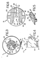
- 1 indicates a photographic cartridge as a whole, comprising a casing element 2 , a spool 3 introduced into casing element 2 and a photographic film 4 wound up on spool 3.
- Film 4 comprises a full-width main portion 5, provided with two sets 6 and 7 of lateral holes and a central portion 8 for image recording. Film 4 comprises then a leader portion 9 , having a reduced width with respect to the main portion 5, formed at one end of film 4.
- Leader 9 is provided with an end portion 10 , in the opposite position with respect to the main portion 5, having three equal round hooking holes 11, circular or preferably elliptical or oval-shaped.
- Casing element 2 is substantially cylindrical in shape, enlarged in correspondence with one of its generating lines, where it is provided with an opening 12 for the passage of the film.
- a light-tight gasket e.g. a couple of black felts 13 and 14 , to prevent light from entering the inside of cartridge 1 thus exposing film 4.
- Spool 3 is free to rotate inside the casing element 2 around its longitudinal axis 15 , following the unwinding and winding-up of film 4 on spool 3 itself.
- Spool 3 comprises a substantially cylindrical winding-up core 16 in axial direction delimited by two circular flanges 17 and 18 .
- Two hollow tangs 19 and 20 protrude from flanges 17 and 18, thus substantially prolongating core 16, and are to engage with an external apparatus (such as a photographic camera) to guide and rotate spool 3; the bigger tang 19 is internally provided with a couple of projecting drive ridges 21 .
- the winding-up core 16 has a central portion 22 with a diameter slightly shorter than that of two lateral portions 23 and 24 , which actually support film 4 when it is wound-up.
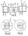
- slit 25 In spool 3 there is a slit 25 , lengthwise extending in the direction of axis 15 for a tract slightly shorter than that of central portion 22 of core 16. Slit 25 passes right through winding-up core 16 and is delimited by two opposite walls 26 and 27 diverging towards an inlet mouth 28 of slit 25.
- a knife 29 On inlet mouth 28, on the side of its wall 26 and as a substantial prolongation thereof, there is formed a knife 29 , i.e. a substantially flat and elongated element extending in the direction of axis 15, comprising a folding portion 30 , in cross section, having a very small bending radius, in particular comprised in the range from 0.10 to 1.00 mm, preferably from 0.15 to 0.50 mm, more preferably equal to about 0.20 mm; on folding portion 30 leader portion 9 is stretched and folded while winding-up film 4 on spool 3.
- a knife 29 i.e. a substantially flat and elongated element extending in the direction of axis 15, comprising a folding portion 30 , in cross section, having a very small bending radius, in particular comprised in the range from 0.10 to 1.00 mm, preferably from 0.15 to 0.50 mm, more preferably equal to about 0.20 mm; on folding portion 30 leader portion 9 is stretched and folded while winding-
- slit 25 there are formed five wide flat supporting elements 31 , 32 , 33 , 34 and 35 , alternatively placed on walls 26 and 27, elements 31, 32 and 33 on wall 26 and elements 34 and 35 on wall 27.
- Supporting elements from 31 to 35 are all provided with respective inclined portions, all indicated with 36 , tapered towards inlet mouth 28.
- the supporting element 32 is in the central position in the direction of axis 15, elements 34 and 35 are lateral, symmetrical with respect to element 32, while elements 31 and 33 are at the extremity and symmetrical with respect to element 32.
- Supporting elements 31, 32 and 33 are reciprocally coplanar along a plane 37
- elements 34 and 35 terminal portions 36 and 21a excluded
- the whole extension in axial direction of the five supporting elements is at least equal to 60% the extension of slit 25, preferably between 75 and 85% (better if equal to about 80%).
- Supporting elements 31 and 33, placed at the ends of slit 25, may also be absent, in a simplified embodiment of the present invention.
- teeth 39 , 40 and 41 respectively on supporting elements 32, 34 and 35; tooth 39, in the central or intermediate position with respect to teeth 40 and 41, results to be formed on wall 26, while teeth 40 and 41, which are lateral with respect to tooth 39, are formed on wall 27.
- Each of teeth 39, 40 and 41 is provided with a hooking throat, indicated with 42 for all teeth, and a tapered back surface, indicated with 43 again for all teeth.
- Throat 42 of each tooth is shaped so as to have a width decreasing towards a rounded bottom 44 of throat 42 itself; the minimum width of throat 42, in correspondence of bottom 44, is slightly higher than the thickness of the photographic film 4, more precisely in the range from 100% to 120% of such thickness, preferably 105%.
- teeth 39, 40 and 41 form both hooking means, to hook leader portion 9 of film 4, and guiding means, to fold and guide leader portion 9 to be hooked.
- Supporting means from 31 to 35 form means to keep flat the end portion 10 provided with hooking holes 11, once hooked to teeth 39, 40 and 41, as it can be better seen hereinafter.
- Spool 3 of cartridge 1 is furthermore provided with means for recognizing the position of spool 3 itself with respect to casing element 2 to allow the inlet mouth 28 of slit 25 to be correctly positioned with respect to opening 12 in casing element 2, thus allowing film 4 to be introduced and hooked when cartridge 1 is closed.
- Such means comprise two regions 45 and 46 having a different depth inside tang 19, in particular two semicircular halves of a circular bottom.
- Film 4 is fastened and wound-up on spool 3 in the following way.
- Film 4 is introduced with its leader portion 9 into inlet mouth 28 of slit 25.
- Film 4 is pushed into slit 25 such that leader portion 9 is guided and progressively (elastically) deformed by supporting planes from 31 to 35 and back surface of teeth 39, 40 and 41, thus taking a wave-like shape with three bends in correspondence of the three teeth 39, 40 and 41.
- leader portion 9 has been hooked, spool 2 is made to rotate to wind-up on itself the film 4 itself.
- leader portion 9 While film 4 is wound-up, leader portion 9 is stretched and folded on knife 29 thus resulting permanently deformed in a cross region 47 , near the main portion 5 of film 4, in particular at a distance therefrom of no more than 5 mm, preferably than 2 mm.
- Region 47 of leader portion 9 results to be weakened by the folding on knife 29 and for this reason it will be called region of relative weakness, this term meaning a region where the natural tensile strength has been reduced in a predetermined way such as to obtain (as better explained hereinafter) a region of preferential breaking under tension.
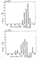
- the hooking between film 4 and spool 3 has been seen to have a very high tensile strength, higher not only than the 89 N breaking point provided for by the already cited ANSI standards, but even than the 110 N point which assures the unoccurrence of such inconveniencies in any type of splicing machines.
- Figure 12 is a histogram showing the breaking frequency, checked at a room temperature of about +20°C. The most frequent value was seen to be 135 N, with a minimum point of 120 N. In all cases, breaking occurred in leader portion 9 in region 10 provided with holes 11, i.e. the weakness region provided in region 47 did not lower the breaking point.
- leader portion 9 The high tensile strength is due to the fact that region 10 in leader portion 9 is kept flat once hooked by elements from 31 to 35. In this way leader portion 9 itself is rendered capable of resisting tension in a way as much uniform as possible; in fact, if leader portion 9 bends under tension, stress concentrations occur thus lowering the total tensile strength.
- Figure 13 is a histogram showing the breaking frequency, checked at a room temperature of about -20°C. The most frequent value was seen to be 125 N with a minimum point of 100 N. In all cases, breaking occurred in leader portion 9 in the relative weakness region 47. In this way, even the films which may break in the splicing machine do not give rise to any practical inconvenience (with the exception perhaps of an alarm signal), since the film which breaks spontaneously appears like a cut film, the leader portion 9 which remains attached thereto being very small. There is therefore no problem in the subsequent splicing with another film.
- region 47 of relative weakness makes somehow acceptable the any way undesired occurrence of the film breaking in the splicing machine.
- the concept of forming a preferential breaking region in the film to avoid or at least limit the drawbacks due to a possible accidental breaking of the film itself in splicing machines is particularly advantageous if the film is fastened to the spool by hooking it thereto, since in this case the tensile strength is lower and therefore breaking more probable.
- the present invention can be advantageously used also with any type of fastening, such as that made by means of adhesive tapes.
Landscapes
- Physics & Mathematics (AREA)
- General Physics & Mathematics (AREA)
- Photographic Developing Apparatuses (AREA)
- Replacement Of Web Rolls (AREA)
Applications Claiming Priority (2)
| Application Number | Priority Date | Filing Date | Title |
|---|---|---|---|
| IT20633/88A IT1217643B (it) | 1988-05-19 | 1988-05-19 | Bobina,caricatore e metodo per il fissaggio di una pellicola fotografica |
| IT2063388 | 1988-05-19 |
Publications (3)
| Publication Number | Publication Date |
|---|---|
| EP0342372A2 true EP0342372A2 (de) | 1989-11-23 |
| EP0342372A3 EP0342372A3 (en) | 1990-07-25 |
| EP0342372B1 EP0342372B1 (de) | 1994-06-08 |
Family
ID=11169827
Family Applications (1)
| Application Number | Title | Priority Date | Filing Date |
|---|---|---|---|
| EP89107012A Expired - Lifetime EP0342372B1 (de) | 1988-05-19 | 1989-04-19 | Spule, Kassette und Methode zur Befestigung eines photographischen Films |
Country Status (5)
| Country | Link |
|---|---|
| EP (1) | EP0342372B1 (de) |
| JP (1) | JPH0219841A (de) |
| CA (1) | CA1319291C (de) |
| DE (1) | DE68915857T2 (de) |
| IT (1) | IT1217643B (de) |
Cited By (3)
| Publication number | Priority date | Publication date | Assignee | Title |
|---|---|---|---|---|
| US5295634A (en) * | 1991-11-18 | 1994-03-22 | Eastman Kodak Company | Film cassette with spool core having fastening hook |
| EP0636924A1 (de) * | 1993-07-27 | 1995-02-01 | Eastman Kodak Company | Gerät und Verfahren zum Entfernen des hinteren Endes eines Filmstreifens von zumindest einem auf einer Filmspule befindlichen Hakens |
| EP0763768A3 (de) * | 1995-09-13 | 1997-08-06 | Fuji Photo Film Co Ltd | Photographische Filmrolle |
Family Cites Families (3)
| Publication number | Priority date | Publication date | Assignee | Title |
|---|---|---|---|---|
| DE3029022A1 (de) * | 1980-07-31 | 1982-02-25 | Agfa-Gevaert Ag, 5090 Leverkusen | Aussenhaken- und fangspule zum rotativen an- und aufwickeln |
| JPS58203436A (ja) * | 1982-05-21 | 1983-11-26 | Konishiroku Photo Ind Co Ltd | 写真フイルム用スプ−ル |
| DE3447215A1 (de) * | 1984-12-22 | 1986-09-18 | Agfa-Gevaert Ag, 5090 Leverkusen | Spule fuer bandfoermige aufzeichnungstraeger, insbesondere fuer fotografische filme |
-
1988
- 1988-05-19 IT IT20633/88A patent/IT1217643B/it active
-
1989
- 1989-04-19 EP EP89107012A patent/EP0342372B1/de not_active Expired - Lifetime
- 1989-04-19 DE DE68915857T patent/DE68915857T2/de not_active Expired - Fee Related
- 1989-05-17 CA CA000599915A patent/CA1319291C/en not_active Expired - Fee Related
- 1989-05-18 JP JP1125485A patent/JPH0219841A/ja active Pending
Cited By (6)
| Publication number | Priority date | Publication date | Assignee | Title |
|---|---|---|---|---|
| US5295634A (en) * | 1991-11-18 | 1994-03-22 | Eastman Kodak Company | Film cassette with spool core having fastening hook |
| EP0636924A1 (de) * | 1993-07-27 | 1995-02-01 | Eastman Kodak Company | Gerät und Verfahren zum Entfernen des hinteren Endes eines Filmstreifens von zumindest einem auf einer Filmspule befindlichen Hakens |
| US5465920A (en) * | 1993-07-27 | 1995-11-14 | Eastman Kodak Company | Tool and method for detaching a trailing end portion of a filmstrip from at least one hook atop a ramp on a film spool inside a film cartridge |
| EP0763768A3 (de) * | 1995-09-13 | 1997-08-06 | Fuji Photo Film Co Ltd | Photographische Filmrolle |
| US5845869A (en) * | 1995-09-13 | 1998-12-08 | Fuji Photo Film Co., Ltd. | Photographic roll film |
| US5934592A (en) * | 1995-09-13 | 1999-08-10 | Fuji Photo Film Co., Ltd. | Photographic roll film |
Also Published As
| Publication number | Publication date |
|---|---|
| CA1319291C (en) | 1993-06-22 |
| EP0342372B1 (de) | 1994-06-08 |
| EP0342372A3 (en) | 1990-07-25 |
| JPH0219841A (ja) | 1990-01-23 |
| DE68915857D1 (de) | 1994-07-14 |
| DE68915857T2 (de) | 1994-11-03 |
| IT8820633A0 (it) | 1988-05-19 |
| IT1217643B (it) | 1990-03-30 |
Similar Documents
| Publication | Publication Date | Title |
|---|---|---|
| EP0378170A2 (de) | Filmkassette | |
| JP2833828B2 (ja) | フィルムカセット | |
| US4335948A (en) | Film retriever | |
| EP0421097B1 (de) | Filmkassette | |
| JPH03168731A (ja) | 写真カメラ | |
| US4074870A (en) | Film retrieval device | |
| US4955555A (en) | Leader-retracting film magazine and method for enclosing film | |
| EP0342372A2 (de) | Spule, Kassette und Methode zur Befestigung eines photographischen Films | |
| EP0445669A2 (de) | Filmkassette | |
| EP0386624A1 (de) | Filmkassette | |
| EP0378169A2 (de) | Filmkassette | |
| US4027832A (en) | Leader-pin | |
| JPH08171181A (ja) | フィルム一体型カメラの製造方法 | |
| CA1191730A (en) | Photographic film assemblage | |
| EP0499203B1 (de) | Filmkassette | |
| US5048770A (en) | Film cassette with exposure status indicator | |
| JP2839403B2 (ja) | 金属線材巻取り用スプール | |
| US5046681A (en) | Film cassette | |
| EP0436785A1 (de) | Filmkassette | |
| US5083720A (en) | Film cassette with cooperating stripper and light-lock | |
| US5102062A (en) | Film cassette with stripper | |
| EP0670511A1 (de) | Filmpatronenladevorrichtung einer photographischen Kamera | |
| US5305042A (en) | Film cassette | |
| EP0786693B1 (de) | Photographischer Film | |
| JPH06332119A (ja) | 写真フィルム巻込み装置 |
Legal Events
| Date | Code | Title | Description |
|---|---|---|---|
| PUAI | Public reference made under article 153(3) epc to a published international application that has entered the european phase |
Free format text: ORIGINAL CODE: 0009012 |
|
| AK | Designated contracting states |
Kind code of ref document: A2 Designated state(s): BE DE FR GB |
|
| PUAL | Search report despatched |
Free format text: ORIGINAL CODE: 0009013 |
|
| AK | Designated contracting states |
Kind code of ref document: A3 Designated state(s): BE DE FR GB |
|
| 17P | Request for examination filed |
Effective date: 19901212 |
|
| 17Q | First examination report despatched |
Effective date: 19921216 |
|
| GRAA | (expected) grant |
Free format text: ORIGINAL CODE: 0009210 |
|
| AK | Designated contracting states |
Kind code of ref document: B1 Designated state(s): BE DE FR GB |
|
| REF | Corresponds to: |
Ref document number: 68915857 Country of ref document: DE Date of ref document: 19940714 |
|
| ET | Fr: translation filed | ||
| PLBE | No opposition filed within time limit |
Free format text: ORIGINAL CODE: 0009261 |
|
| STAA | Information on the status of an ep patent application or granted ep patent |
Free format text: STATUS: NO OPPOSITION FILED WITHIN TIME LIMIT |
|
| 26N | No opposition filed | ||
| PGFP | Annual fee paid to national office [announced via postgrant information from national office to epo] |
Ref country code: BE Payment date: 19970410 Year of fee payment: 9 |
|
| PG25 | Lapsed in a contracting state [announced via postgrant information from national office to epo] |
Ref country code: BE Free format text: LAPSE BECAUSE OF NON-PAYMENT OF DUE FEES Effective date: 19980430 |
|
| BERE | Be: lapsed |
Owner name: MINNESOTA MINING AND MFG CY Effective date: 19980430 |
|
| REG | Reference to a national code |
Ref country code: FR Ref legal event code: TP |
|
| REG | Reference to a national code |
Ref country code: GB Ref legal event code: 732E |
|
| REG | Reference to a national code |
Ref country code: GB Ref legal event code: IF02 |
|
| PGFP | Annual fee paid to national office [announced via postgrant information from national office to epo] |
Ref country code: DE Payment date: 20020430 Year of fee payment: 14 |
|
| PGFP | Annual fee paid to national office [announced via postgrant information from national office to epo] |
Ref country code: FR Payment date: 20030403 Year of fee payment: 15 |
|
| REG | Reference to a national code |
Ref country code: GB Ref legal event code: 732E |
|
| PG25 | Lapsed in a contracting state [announced via postgrant information from national office to epo] |
Ref country code: DE Free format text: LAPSE BECAUSE OF NON-PAYMENT OF DUE FEES Effective date: 20031101 |
|
| REG | Reference to a national code |
Ref country code: FR Ref legal event code: TP |
|
| PGFP | Annual fee paid to national office [announced via postgrant information from national office to epo] |
Ref country code: GB Payment date: 20040312 Year of fee payment: 16 |
|
| PG25 | Lapsed in a contracting state [announced via postgrant information from national office to epo] |
Ref country code: FR Free format text: LAPSE BECAUSE OF NON-PAYMENT OF DUE FEES Effective date: 20041231 |
|
| REG | Reference to a national code |
Ref country code: FR Ref legal event code: ST |
|
| PG25 | Lapsed in a contracting state [announced via postgrant information from national office to epo] |
Ref country code: GB Free format text: LAPSE BECAUSE OF NON-PAYMENT OF DUE FEES Effective date: 20050419 |
|
| GBPC | Gb: european patent ceased through non-payment of renewal fee |
Effective date: 20050419 |