EP0342253B1 - Montage d'un capteur de force dans une plate-forme de mesure - Google Patents
Montage d'un capteur de force dans une plate-forme de mesure Download PDFInfo
- Publication number
- EP0342253B1 EP0342253B1 EP88107939A EP88107939A EP0342253B1 EP 0342253 B1 EP0342253 B1 EP 0342253B1 EP 88107939 A EP88107939 A EP 88107939A EP 88107939 A EP88107939 A EP 88107939A EP 0342253 B1 EP0342253 B1 EP 0342253B1
- Authority
- EP
- European Patent Office
- Prior art keywords
- base plate
- force transducer
- mounting
- measuring platform
- platform according
- Prior art date
- Legal status (The legal status is an assumption and is not a legal conclusion. Google has not performed a legal analysis and makes no representation as to the accuracy of the status listed.)
- Expired - Lifetime
Links
- 239000007787 solid Substances 0.000 claims 1
- 239000000758 substrate Substances 0.000 claims 1
- 238000003466 welding Methods 0.000 abstract description 5
- 238000005476 soldering Methods 0.000 abstract description 3
- 238000005260 corrosion Methods 0.000 abstract description 2
- 230000007797 corrosion Effects 0.000 abstract description 2
- 238000005219 brazing Methods 0.000 abstract 1
- 230000002708 enhancing effect Effects 0.000 abstract 1
- 239000011347 resin Substances 0.000 abstract 1
- 229920005989 resin Polymers 0.000 abstract 1
- 230000035939 shock Effects 0.000 abstract 1
- 238000005259 measurement Methods 0.000 description 12
- 238000003754 machining Methods 0.000 description 10
- 230000036316 preload Effects 0.000 description 6
- 238000005516 engineering process Methods 0.000 description 4
- 238000003780 insertion Methods 0.000 description 4
- 230000037431 insertion Effects 0.000 description 4
- 238000013461 design Methods 0.000 description 3
- 238000010276 construction Methods 0.000 description 2
- 238000011161 development Methods 0.000 description 2
- 230000018109 developmental process Effects 0.000 description 2
- 230000007613 environmental effect Effects 0.000 description 2
- 239000007789 gas Substances 0.000 description 2
- 238000009434 installation Methods 0.000 description 2
- 230000010354 integration Effects 0.000 description 2
- 239000007788 liquid Substances 0.000 description 2
- 238000004519 manufacturing process Methods 0.000 description 2
- 238000000034 method Methods 0.000 description 2
- 206010040925 Skin striae Diseases 0.000 description 1
- 208000031439 Striae Distensae Diseases 0.000 description 1
- 238000004458 analytical method Methods 0.000 description 1
- 239000004568 cement Substances 0.000 description 1
- 238000011109 contamination Methods 0.000 description 1
- 230000007547 defect Effects 0.000 description 1
- 230000002939 deleterious effect Effects 0.000 description 1
- 238000003745 diagnosis Methods 0.000 description 1
- 238000003825 pressing Methods 0.000 description 1
- 229910000679 solder Inorganic materials 0.000 description 1
Images

Classifications
-
- G—PHYSICS
- G01—MEASURING; TESTING
- G01L—MEASURING FORCE, STRESS, TORQUE, WORK, MECHANICAL POWER, MECHANICAL EFFICIENCY, OR FLUID PRESSURE
- G01L1/00—Measuring force or stress, in general
- G01L1/26—Auxiliary measures taken, or devices used, in connection with the measurement of force, e.g. for preventing influence of transverse components of force, for preventing overload
-
- A—HUMAN NECESSITIES
- A61—MEDICAL OR VETERINARY SCIENCE; HYGIENE
- A61B—DIAGNOSIS; SURGERY; IDENTIFICATION
- A61B5/00—Measuring for diagnostic purposes; Identification of persons
- A61B5/103—Detecting, measuring or recording devices for testing the shape, pattern, colour, size or movement of the body or parts thereof, for diagnostic purposes
- A61B5/1036—Measuring load distribution, e.g. podologic studies
-
- B—PERFORMING OPERATIONS; TRANSPORTING
- B23—MACHINE TOOLS; METAL-WORKING NOT OTHERWISE PROVIDED FOR
- B23Q—DETAILS, COMPONENTS, OR ACCESSORIES FOR MACHINE TOOLS, e.g. ARRANGEMENTS FOR COPYING OR CONTROLLING; MACHINE TOOLS IN GENERAL CHARACTERISED BY THE CONSTRUCTION OF PARTICULAR DETAILS OR COMPONENTS; COMBINATIONS OR ASSOCIATIONS OF METAL-WORKING MACHINES, NOT DIRECTED TO A PARTICULAR RESULT
- B23Q17/00—Arrangements for observing, indicating or measuring on machine tools
- B23Q17/09—Arrangements for observing, indicating or measuring on machine tools for indicating or measuring cutting pressure or for determining cutting-tool condition, e.g. cutting ability, load on tool
- B23Q17/0952—Arrangements for observing, indicating or measuring on machine tools for indicating or measuring cutting pressure or for determining cutting-tool condition, e.g. cutting ability, load on tool during machining
- B23Q17/0966—Arrangements for observing, indicating or measuring on machine tools for indicating or measuring cutting pressure or for determining cutting-tool condition, e.g. cutting ability, load on tool during machining by measuring a force on parts of the machine other than a motor
-
- G—PHYSICS
- G01—MEASURING; TESTING
- G01G—WEIGHING
- G01G19/00—Weighing apparatus or methods adapted for special purposes not provided for in the preceding groups
- G01G19/44—Weighing apparatus or methods adapted for special purposes not provided for in the preceding groups for weighing persons
-
- G—PHYSICS
- G01—MEASURING; TESTING
- G01L—MEASURING FORCE, STRESS, TORQUE, WORK, MECHANICAL POWER, MECHANICAL EFFICIENCY, OR FLUID PRESSURE
- G01L5/00—Apparatus for, or methods of, measuring force, work, mechanical power, or torque, specially adapted for specific purposes
- G01L5/16—Apparatus for, or methods of, measuring force, work, mechanical power, or torque, specially adapted for specific purposes for measuring several components of force
- G01L5/167—Apparatus for, or methods of, measuring force, work, mechanical power, or torque, specially adapted for specific purposes for measuring several components of force using piezoelectric means
Definitions
- the invention relates to a measuring platform with at least one electromechanical force transducer according to claim 1.
- Measuring platforms are used in particular in machining technology and biomechanics to measure forces in one or more directions, and possibly also to measure torques.
- the machining process can be dynamically analyzed, which means that the machining parameters can be optimized.
- the sequence of movements e.g. when walking, be analyzed, which enables a diagnosis of defects.
- Such measuring platforms are e.g. in DE-A-19 52 522, DE-A-33 13 960 and CH-A-595 623.
- the measuring platforms used in biomechanics or machining technology mostly consist of a cover plate and a base plate or a base frame with one or more force transducers arranged in between.
- a measuring platform is described in FR-A-2 325 916.
- the force transducer has a flange provided with screw holes on the end face, which is seated flush on the base plate of the measuring platform.
- the connection between the force transducer and the base plate is made through the screw holes in the flange Threaded holes of the base plate, screwed fastening screws.
- the force transducers of the known arrangement are therefore only imperfectly or not at all protected or sealed against external environmental influences.
- Another consequence of the known design of the measuring platform is a greater overall height and a loss of rigidity of the measuring system.
- the invention is based on the object of creating a measuring platform of the type mentioned at the outset, in which the aforementioned disadvantages are essentially eliminated.
- the invention is intended to enable a tight, essentially shielded mounting of the force transducers in such measuring platforms.
- the mounting flange which is provided in the area of at least one axial end of the force transducer, is received in a correspondingly designed mounting hole in the base plate of the measuring platform and is thus permanently sealed by welding, soldering or putty.
- the differently dimensioned axial end areas of the force transducer allow the transducer to be pushed in from outside through the mounting hole until the mounting flange comes to rest in the mounting hole. After the permanent connection with the mounting hole, the force transducer becomes an integral part of the base plate, which is essentially shielded from external influences.
- the force transducer has radial signal lines at an intermediate point between its axial ends, which come to lie within the base plate in suitable recesses provided therein and are therefore also shielded against external influences.
- An arrangement with a force transducer is known from FR-A-2 285 603, which, in broad accordance with the feature a) of claim 1, has a radial mounting flange by means of which the force transducer can be supported on a shoulder surface of a shoulder bore in a component .
- the known arrangement is designed for measuring the pressures in liquids and gases, so that the force transducer is exposed to these environmental influences.
- signal can only be derived by the transducer itself and the associated assembly aids.
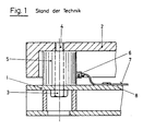
- Fig. 1 shows a partial longitudinal section through a conventional measuring platform, such as is used for example in biomechanics (prior art). It is composed of a base plate 1, a cover plate 2 and an intermediate force transducer 5, which receives its pretension via a pretensioning screw 3 which is screwed into a thread 4 in the cover plate.
- the force transducer is drilled centrally to receive the preload screw 3, as is the upper part of the base plate 1 shown here in box form.
- the tightening of the preload screw 3 can be done by means of a wrench, which is shown in FIG. 1, but not designated, in the lower part of the bore the base plate 1 can be performed.
- the measurement package consisting, for example, of piezoelectric disks is not visible.
- the signals are transmitted via a plug 6 and a signal line 7, which is fixed, for example, to the base plate 1 by means of a fastening element 8. 1 shows that the measuring platform according to the prior art is not tightly closed. Dirty, aggressive liquids and gases can penetrate to the sensitive transducers, plugs and signal lines. In addition, the measuring platform has considerable expansion in the thickness direction.
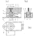
- Fig. 2 shows a partial longitudinal section of a force transducer 5, installed on the one hand in a box-shaped base plate 1, on the other hand in the force-introducing cover plate 2.
- the numbers have the same meaning as in Fig. 1.
- the force transducer 5 is visible here in its individual elements.
- 14 means the front part of the transducer, which is received by a non-continuous bore in the lower part of the base plate 1, 15 the base part, which carries a flange 10.
- a conventionally constructed piezoelectric measuring package 16 for force measurement with lateral connections for signal lines 7.
- the cylindrical force introduction part 9 of the force transducer 5 tapers to an extension (not shown) with a screw-shaped end part, which is received through a hole in the cover plate 2.
- a clamping nut 11 carries the corresponding internal thread and lies on a shoulder in the perforated cover plate 1. By tightening the screw nut 11, the cover plate 2 is pressed against the force introduction part 9 of the force transducer 5, as a result of which the measuring platform is held together and the forces acting on it from the outside can be transmitted to the measuring package 16.
- FIG. 2 The force transducer 5, together with the side signal lines 7, is fully integrated in the box-shaped base plate 1.
- the front mounting flange 10 is firmly connected to the base plate, for example by welding, soldering or putty.
- the connections 13 of the box are tight against the outside.
- the box is completely sealed against external influences, which could have a deleterious effect on the sensitive force transducers 5 (contamination, corrosion).
- it In order to achieve this seal and the integration of the transducer 5 in the base plate 1, it must be inserted as a finished component, together with the side signal lines 7, into the box-shaped base plate 1 and can be fixed after this process.
- this is done in a simple manner such that the base part 15 of the force transducer 5 is provided with a mounting flange 10, the diameter of which is larger than the diameter of the front part 14 of the transducer 5.
- the flange 10 fits into a corresponding hole in the upper part of the base plate 1.
- FIG. 3 and 4 show the same measuring platform as FIG. 2, FIG. 3 shows it in cross-section, FIG. 4 in plan. In the following, the digits always have the same meaning as before.
- Fig. 3 the electrical connection 17 between the front part 14 and base part 15 of the force transducer 5 is still visible (both must be at the same potential, e.g. earth potential).
- 4 shows the frame-shaped and box-shaped welded construction of the illustrated base plate 1.
- the bore 18 is used to fasten the measuring platform to the floor, for example.
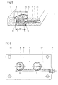
- FIG. 5 shows a section of a measuring platform, as is used, for example, when measuring forces and torques during machining processes.
- the force transducer 5 is integrated in a full base plate 1 here.
- a recess 23 is made in the base plate 1 only for receiving the signal lines 7.
- the transducer 5 contains a multi-part, conventional, piezoelectric measurement package 16, which is sensitive to pressure both in the z direction and in the y and / or x direction.
- the transducer 5 is preferably located in a two-stage through bore, not shown, and carries mounting flanges 10, 19 in the region of both axial ends.
- the base-side mounting flange 10 has a larger diameter D 1 than the front-side mounting flange 19 with the diameter D2.
- D 1 the diameter of the base plate 1.
- the finished transducer 5 and the signal lines 7 can be easily inserted into the through bore of the base plate 1 as a result of these design conditions, whereupon the two mounting flanges 10, 19 can be welded, soldered or cemented in (show as welds 12, 20).
- the base plate 1 shown in FIG. 5 can be used as a single plate for force measurements, for example in machining technology. It can be inserted into a suitable recess in a single machine part, but also between two machine parts.
- the mechanical prestressing of the force transducers 5 required for force measurements can be generated, for example, in such a way that they protrude on one or both sides by a certain, small amount over the surfaces of the base plate 1 that are not designated. In the application example mentioned, the connection surfaces of the cutout would then press against the force transducers 5 (possibly with the interposition of e.g. a film) and pre-tension them.
- FIG. 6 shows the floor plan of a complete base plate 1.
- one or more force transducers 5 can be used to measure a machining process. Shown here are two force transducers A and B, both of which are pressure-sensitive in the z-direction, and one (A) in the y- and the other (B) in the x-direction. However, both can also be sensitive in the same direction, or both can be sensitive to thrust in both the x and y directions. Also shown is the recess 23 for the signal lines 7 (not shown in this figure) and the sealed cable connection socket 24 for the connection of external cables, for example coaxial cables. With the tight welds of the force transducers 5 already shown in FIG. 5, the base plate 1 forms a dense, compact measuring unit with integrated force transducers 5, which also has a very high rigidity and thus a high cut-off frequency, and is therefore also suitable for the analysis of very rapid processes suitable, such as occur during machining processes.
- the illustrated base plate 1 can be attached as such, for example, between two machine parts (or, in the case of biomechanical applications, on the floor) and firmly screwed to one part (or the floor) with fastening screws through the bores 22.
- the base plate 1 can also lie between two force introduction plates (not shown here) and form a measuring platform with them.
- the necessary mechanical pretensioning of the force transducers can be achieved in such a way that their height is dimensioned such that they protrude by a certain amount on one or both sides of the base plate 1.
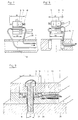
- FIG. 7 and 8 represent, in summary, again the most important types of installation of the force transducers according to the invention.
- the base plate 1 consists of a box, that is to say it is hollow, in FIG. 8 it is full except for recesses.
- the force transducer 5 in Fig. 7 carries only at its base end ("top" in the figure) a mounting flange 10 with the diameter D 1, the opposite front end with the diameter D 2 carries none.
- the base-side diameter D 1 is larger than the front-side D 2.
- the mounting flange 10 fits into the mounting hole 25 of the base plate 1, the front part 14 of the sensor 5 fits into the non-continuous mounting hole 26.
- the signal lines 7 are advantageously first led in and out laterally, whereupon the transducer 5 can be pushed.
- the essentially full base plate 1 in Fig. 8 (corresponding to the base plate in Fig. 5) contains a two-stage through-hole for the force transducer 5 provided with two mounting flanges 10, 19, the diameter D 1 of the base-side mounting flange 10 again being larger than the diameter D 2 of the front mounting flange 19. These two diameters correspond to the diameters of the two-stage through hole.
- the signal lines 7 are first inserted into the base-side bore in the base plate 1 and then the transducer 5 into the through bore inserted until it assumes the position shown in dotted lines in FIG. 8.
- Fig. 7 and Fig. 8 make it clear that the assembly of the force transducer in the base plate is considerably simplified in that the transducer has a larger diameter at its base end ("top" in the figure) than at its front end, and that the tightness of the measuring system in the case of a box-shaped base plate requires the welding in of a mounting flange, whereas in the case of a full base plate two mounting flanges are generally welded in.
- FIGS. 9 and 10 represent embodiments of measuring platforms with force transducers according to the invention.
- FIG. 9 shows a measuring platform, consisting of a base plate 1 and a cover plate 2, which is anchored to the base plate 36 by means of one or more fastening screws 33 (biomechanical application).
- the measuring platform can also be mounted between two machine parts or in a recess in a machine part.
- the base plate 1 corresponds essentially to that shown in FIG. 5.
- the main difference is that the force transducer 5 has a central bore 27.
- the base plate 1, although it essentially represents a full plate, is provided with a two-stage through-hole in which the sensor 5 provided with only one mounting flange 10 is accommodated.
- the likewise centrally pierced piezoelectric measurement package 16 lies between the base part 15 of the transducer 5 and the step of the through-hole in the base plate 1 which is not designated.
- the insertion of the transducer 5 into the base plate 1 takes place analogously to that shown in FIGS. 5, 6 or 7 Embodiments of the invention, which is made possible by the fact that the transducer 5 also has a larger diameter (D 1) at its base end than at its front end (D 2), which fits as a tubular extension 28 into the narrower section of the two-stage through hole.
- the base plate 1 shown in FIG. 9 carries a cover plate 2 with a bore (not designated) for the purpose of receiving the continuous fastening screw 33.
- the base plate 36 also contains a bore with an internal thread (not designated) for the purpose of receiving the threaded section of the fastening screw 33.
- an internal thread not designated
- the fastening screw 33 was tightened so tightly that the cover plate 2 touches the base plate 1 in a force-locking manner. This creates a force shunt, ie the force transducer (s) 5 no longer receives the full acting force. A part of it is transferred directly to the base plate 1. This can be an advantage for large forces.
- the force transducer 5 has no continuous central bore here, because the mechanical preload of the piezoelectric measuring package 16 is not generated by means of a central continuous, separate preload screw.
- the sensor 5 has at its front end a tubular mounting extension 28 which is received by an external thread through the internal thread of a clamping nut 31, which is not shown. This clamping nut 31 fits into a hole in a wall of the box-shaped base plate 1, on the inside of which the ring-shaped base 30 for the measuring package 16 is welded in such a way that it overlaps the hole mentioned.
- the base part 15 of the force transducer 5 is pressed against the piezoelectric measuring package 16, as a result of which this is mechanically preloaded.
- the base part 15 of the force transducer 5 contains a bore 32 with a thread for fastening a force-introducing cover plate (not shown). This cover plate is pierced at the points 5 opposite the transducers.
- the bores accommodate the fastening screws that match the threads of the bores 32.
- the base-side diameter D 1 is larger than the front-side D 2, so that the insertion ben the laterally leading signal lines 7 is possible, whereupon the transducer 5 is introduced.
- FIG. 11 shows a further development of the measurement platforms shown in FIGS. 9 and 10.
- the base plate 1 shown in FIG. 10 now carries a cover plate 2 which fits into the threaded bore 32 of the force transducer 5 (already shown in FIG. 10) Fastening screw 34 is screwed onto the force transducer 5.
- This measuring platform can also contain one or more force transducers.
- the base part 15 of the force transducer 5 projects over the base plate 1. It can thereby be achieved that a force acting on the cover plate 2 is fully absorbed by the force transducer (s) 5 because the base plate 1 and cover plate 2 do not touch (main force connection).
- the tubular extension 28 of the force transducer 5 has at its front end an external thread 37 which fits into an internal thread of a bore (not designated) in the base plate 1.
- the measurement package 16 can be pre-stressed.
- the aforementioned threaded hole in the base plate 1 merges at its front end into a smooth hole of smaller diameter, which creates a step which carries the head of a screw 35.
- the screw 35 can be received in the base plate 36 through a corresponding internal thread of a bore (not designated). By tightening the screw 35, which must be done before the cover plate 2 is fastened, the base plate 1 can be firmly anchored in the base plate 36.
- This type of fastening of the base plate 1 to the base plate 36 can be carried out by means of several screws 35 if the measuring platform contains several force transducers 5. This creates a stable, firmly anchored measuring system.
- the measuring platform shown represents an embodiment which is preferably used in biomechanics. However, the measuring platform can also lie between two machine parts or in a recess in a machine part.
- the base plate 36 then represents a wall surface of a machine part or the aforementioned recess.
- the present invention relates to measurement platforms or Base plates as used in machining technology and biomechanics. It enables the integration of force transducers in the base plate of a measuring platform or in a single base plate in a simple manner. So far, the force transducers have been mounted on the base plate. Due to the fact that the force transducers have a smaller diameter on the front than on the base side, whereby the transducers fit into the holes in the base plate, it is possible to sink the force transducers into the mounting bores after welding and to weld, solder or cement them. This creates a universally applicable base plate with a permanently mounted coaxial or multiple plug and fully protected and tightly inserted cable connections and signal lines.
- the cavities can be filled with a hardening gel after insertion of the signal lines so that they are better insulated and fixed in their position.
- intermediate amplifiers can be introduced into the cavities mentioned.
- the rigidity of the measurement platforms according to the invention is greater than that of the previous measurement platforms because of the more compact design and the smaller thickness.
- the embodiments of the invention shown in the figures contain piezoelectric pickup elements. However, other electromechanical pickup elements such as piezoresistive or with stretch marks can also be provided.
- the measuring platforms can contain one or more force transducers, wherein the force transducers can be sensitive to thrust in one or both directions (x, y), and possibly additionally sensitive to pressure in the z direction. However, it is also possible for the force transducer (s) to be pressure-sensitive only in the z direction.
Landscapes
- Physics & Mathematics (AREA)
- Health & Medical Sciences (AREA)
- Life Sciences & Earth Sciences (AREA)
- General Physics & Mathematics (AREA)
- Engineering & Computer Science (AREA)
- Biomedical Technology (AREA)
- Medical Informatics (AREA)
- Dentistry (AREA)
- Biophysics (AREA)
- Pathology (AREA)
- Mechanical Engineering (AREA)
- Heart & Thoracic Surgery (AREA)
- Oral & Maxillofacial Surgery (AREA)
- Molecular Biology (AREA)
- Surgery (AREA)
- Animal Behavior & Ethology (AREA)
- General Health & Medical Sciences (AREA)
- Public Health (AREA)
- Veterinary Medicine (AREA)
- Force Measurement Appropriate To Specific Purposes (AREA)
- Measurement Of Force In General (AREA)
Claims (12)
- Plate-forme de mesure avec au moins un capteur de force électromécanique présentant les caractéristiques suivantes :a) pour la fixation à une plaque de base (1) de la plate-forme de mesure le capteur de force présente, dans la zone de son extrémité axiale,un flasque de montage (10) essentiellement radial avec un diamètre extérieur plus grand que le diamètre extérieur du capteur de force dans la zone de son autre extrémité axiale,b) le flasque de montage (10) du capteur de force est logé dans un trou de montage de la plaque de base (1) et est fixé à celle-ci de manière étanche par soudage, brasage ou mastiquage, etc)des conducteurs de signaux (7) essentiellement radiaux, disposés dans la plaque de base (1), partent du capteur de force à un endroit intermédiaire entre ses extrémités axiales.
- Plate-forme de mesure selon la revendication 1, caractérisée en ce qu'un autre flasque de montage (19) ayant un diamètre extérieur (D2) plus petit que le diamètre extérieur (D1) du premier flasque de montage (10) essentiellement radial et prévu dans la zone de l'autre extrémité axiale du capteur de force peut être logé dans un autre trou de montage de la plaque de base (1) qui est orienté en direction essentiellement axiale par rapport au premier trou de montage.
- Plate-forme de mesure selon la revendication 1 ou 2, caractérisée en ce que la plaque de base (1) a un profil en caisson.
- Plate-forme de mesure selon l'une des revendications 1 à 3, caractérisée en ce que la plaque de base (1) est une plaque pleine.
- Plate-forme de mesure selon l'une des revendications précédentes, caractérisée en ce que le capteur de force présente au moins une embase de montage (28) axiale et s'étendant depuis l'une des extrémités axiales.
- Plate-forme de mesure selon la revendication 5, caractérisée en ce que l'embase de montage (28) est reprise dans un trou à double gradin de la plaque de base (1) et qu'une vis de fixation (35),destinée à fixer la plaque de base (1) sur un support, prend appui sur un redan du trou de montage à double gradin.
- Plate-forme de mesure selon la revendication 5, caractérisée en ce que l'embase de montage axiale (28) est prévue à l'extrémité axiale du capteur de force opposée au premier flasque de montage (10).
- Plate-forme de mesure selon la revendication 5, caractérisée en ce que l'embase de montage (28) présente un trou de passage central (27) destiné à recevoir une vis de précontrainte (33).
- Plate-forme de mesure selon la revendication 5, caractérisée en ce que l'embase de montage (28) est pourvue d'un filetage destiné à coopérer avec un écrou de serrage (31) prenant appui sur la plaque de base (1) afin de précontraindre le dispositif de mesure du capteur de force.
- Plate-forme de mesure selon l'une des revendications précédentes, caractérisée en ce qu'un trou fileté (32) est pratiqué dans l'extrémité axiale du capteur de force tournée vers le premier flasque de montage (10).
- Plate forme de mesure selon l'une des revendications précédentes, caractérisée en ce que les cavités de la plaque de base (1) recevant les conducteurs de signaux (7) du capteur de force sont renplies d'un gel isolant durcissable.
- Plate-forme de mesure selon l'une des revendications prcédentes, caractérisée en ce qu'un ou plusieurs amplificateurs intermédiaires sont disposés dans les cavités de la plaque de base (1).
Priority Applications (4)
| Application Number | Priority Date | Filing Date | Title |
|---|---|---|---|
| EP88107939A EP0342253B1 (fr) | 1988-05-18 | 1988-05-18 | Montage d'un capteur de force dans une plate-forme de mesure |
| AT88107939T ATE84612T1 (de) | 1988-05-18 | 1988-05-18 | Kraftaufnehmer zum einbau in messplattformen. |
| DE8888107939T DE3877563D1 (de) | 1988-05-18 | 1988-05-18 | Kraftaufnehmer zum einbau in messplattformen. |
| US07/340,706 US4974454A (en) | 1988-05-18 | 1989-04-20 | Force transducers for fitting in force plates |
Applications Claiming Priority (1)
| Application Number | Priority Date | Filing Date | Title |
|---|---|---|---|
| EP88107939A EP0342253B1 (fr) | 1988-05-18 | 1988-05-18 | Montage d'un capteur de force dans une plate-forme de mesure |
Publications (2)
| Publication Number | Publication Date |
|---|---|
| EP0342253A1 EP0342253A1 (fr) | 1989-11-23 |
| EP0342253B1 true EP0342253B1 (fr) | 1993-01-13 |
Family
ID=8198981
Family Applications (1)
| Application Number | Title | Priority Date | Filing Date |
|---|---|---|---|
| EP88107939A Expired - Lifetime EP0342253B1 (fr) | 1988-05-18 | 1988-05-18 | Montage d'un capteur de force dans une plate-forme de mesure |
Country Status (4)
| Country | Link |
|---|---|
| US (1) | US4974454A (fr) |
| EP (1) | EP0342253B1 (fr) |
| AT (1) | ATE84612T1 (fr) |
| DE (1) | DE3877563D1 (fr) |
Cited By (2)
| Publication number | Priority date | Publication date | Assignee | Title |
|---|---|---|---|---|
| CN106403866A (zh) * | 2015-07-31 | 2017-02-15 | 北京航天计量测试技术研究所 | 一种适用于无安装孔线位移传感器组件的安装夹具 |
| US11852545B2 (en) | 2018-01-24 | 2023-12-26 | Avl List Gmbh | Measuring device and method for determining a force and/or a torque on a torque-transmitting shaft |
Families Citing this family (13)
| Publication number | Priority date | Publication date | Assignee | Title |
|---|---|---|---|---|
| DK284790D0 (da) * | 1990-11-29 | 1990-11-29 | Lars Erik Brath | Fremgangsmaade og apparat til sammensmeltning af separate termoplastiske legemer |
| DE4402529A1 (de) * | 1993-02-17 | 1994-08-18 | Fischer Georg Verkehrstechnik | Anordnung von Meßmitteln an einem Sattelfahrzeug |
| DE4402525C2 (de) * | 1993-02-17 | 1998-10-29 | Fischer Georg Verkehrstechnik | Anordnung von Meßmitteln an einem eine Sattelzugmaschine und einen Sattelanhänger aufweisenden Sattelfahrzeug |
| US5991676A (en) * | 1996-11-22 | 1999-11-23 | Breed Automotive Technology, Inc. | Seat occupant sensing system |
| EP0866323A3 (fr) * | 1997-02-25 | 1999-02-17 | K.K. Holding AG | Platforme de mesure pour la surveillance du poids et du système de freinage |
| US6923068B2 (en) * | 2003-06-19 | 2005-08-02 | Dynisco, Inc. | Pressure transducer |
| ES2629101T3 (es) * | 2008-05-05 | 2017-08-07 | Kistler Holding Ag | Célula de carga |
| JP5880934B2 (ja) * | 2011-12-20 | 2016-03-09 | セイコーエプソン株式会社 | センサーデバイス、センサーモジュール、力検出装置、ロボット |
| DE102012005555B3 (de) * | 2012-03-21 | 2013-08-22 | Audi Ag | Messplatte mit Sensoren |
| TWI515632B (zh) | 2012-06-26 | 2016-01-01 | 緯創資通股份有限公司 | 隨觸即用輸入裝置以及操作方法 |
| US20150051514A1 (en) * | 2013-08-15 | 2015-02-19 | Safety in Motion, Inc. | Concussion/balance evaluation system and method |
| EP3526565A1 (fr) * | 2016-10-17 | 2019-08-21 | Kistler Holding AG | Capteur de force et de couple, module récepteur de force pour un tel capteur de force et de couple et robot comprenant un tel capteur de force et de couple |
| AT521702B1 (de) * | 2019-03-11 | 2020-04-15 | Piezocryst Advanced Sensorics | Messsystem, geeignet für den einbau zwischen moment- und/oder kraftübertragenden maschinenteilen |
Family Cites Families (14)
| Publication number | Priority date | Publication date | Assignee | Title |
|---|---|---|---|---|
| US3091961A (en) * | 1960-05-11 | 1963-06-04 | Piell Reinhart | Load-cell mounting for mill-roll chock |
| US3222628A (en) * | 1962-12-31 | 1965-12-07 | Baldwin Lima Hamilton Corp | Force measuring device |
| CH472668A (de) * | 1967-09-05 | 1969-05-15 | Kistler Instrumente Ag | Einrichtung mit einer Mehrkomponenten-Piezomesszelle |
| CH476990A (de) * | 1968-07-30 | 1969-08-15 | Kistler Instrumente Ag | Kraftaufnehmer mit mindestens einem zwischen zwei Kraftübertragungslagern angeordneten Piezoelement |
| US3788133A (en) * | 1972-08-25 | 1974-01-29 | Toroid Corp | Force sensing transducer |
| CH569961A5 (fr) * | 1974-09-17 | 1975-11-28 | Kistler Instrumente Ag | |
| SE404762B (sv) * | 1975-03-11 | 1978-10-30 | Asea Ab | Lastcellskonstruktion for metning av valskraft i valsverk |
| CH587475A5 (fr) * | 1975-09-26 | 1977-04-29 | Kistler Instrumente Ag | |
| CH595623A5 (fr) * | 1975-12-19 | 1978-02-15 | Kistler Instrumente Ag | |
| DE3019751C2 (de) * | 1980-05-23 | 1983-12-29 | J.G. Weisser Söhne, 7742 St Georgen | Einrichtung zur Messung der Schnittkraft von Schneidwerkzeugen eines Mehrfachwerkzeugträgers |
| CH656464A5 (de) * | 1982-04-20 | 1986-06-30 | Kistler Instrumente Ag | Kraftmessplattform mit adapterplatte. |
| US4493220A (en) * | 1982-11-23 | 1985-01-15 | Advanced Mechanical Technology, Inc. | Force measuring platform and load cell therefor using strain gages to measure shear forces |
| US4630490A (en) * | 1985-07-12 | 1986-12-23 | Carron & Company | Compression strain gauge transducer assembly |
| DE3763252D1 (de) * | 1986-02-13 | 1990-07-19 | Pfister Gmbh | Plattformwaage und methode zu ihrer herstellung. |
-
1988
- 1988-05-18 EP EP88107939A patent/EP0342253B1/fr not_active Expired - Lifetime
- 1988-05-18 AT AT88107939T patent/ATE84612T1/de not_active IP Right Cessation
- 1988-05-18 DE DE8888107939T patent/DE3877563D1/de not_active Expired - Fee Related
-
1989
- 1989-04-20 US US07/340,706 patent/US4974454A/en not_active Expired - Fee Related
Cited By (2)
| Publication number | Priority date | Publication date | Assignee | Title |
|---|---|---|---|---|
| CN106403866A (zh) * | 2015-07-31 | 2017-02-15 | 北京航天计量测试技术研究所 | 一种适用于无安装孔线位移传感器组件的安装夹具 |
| US11852545B2 (en) | 2018-01-24 | 2023-12-26 | Avl List Gmbh | Measuring device and method for determining a force and/or a torque on a torque-transmitting shaft |
Also Published As
| Publication number | Publication date |
|---|---|
| DE3877563D1 (de) | 1993-02-25 |
| ATE84612T1 (de) | 1993-01-15 |
| US4974454A (en) | 1990-12-04 |
| EP0342253A1 (fr) | 1989-11-23 |
Similar Documents
| Publication | Publication Date | Title |
|---|---|---|
| EP0342253B1 (fr) | Montage d'un capteur de force dans une plate-forme de mesure | |
| EP1327128B1 (fr) | Dispositif de mesure de pression | |
| DE69935896T2 (de) | Kompakte Struktur eines Gassensors und seine Produktionsmethode | |
| EP0927344B1 (fr) | Unite capteur de pression, destinee notamment au genie automobile | |
| DE102004030844B4 (de) | Verfahren zur Herstellung eines Sensors sowie Sensor | |
| DE19936300A1 (de) | Druckerkennungsvorrichtung, Verbindungsteil hierfür, sowie Verfahren zur Herstellung eines elektrischen Bauteileverbinders | |
| DE102018211471B3 (de) | Batteriegehäuse | |
| WO1994021992A1 (fr) | Convertisseur de mesure de pression differentielle | |
| DE3614198C2 (fr) | ||
| DE102012014407A1 (de) | Vorrichtung zur Erfassung und Verarbeitung von Sensormesswerten und/oder zur Steuerung von Aktuatoren | |
| WO1987000128A1 (fr) | Capteur de pression | |
| EP0615611A1 (fr) | Dispositif pour la fixation d'un boitier. | |
| DE19740363A1 (de) | Gassensor | |
| EP1471335A2 (fr) | Capteur avec filetage en arrière pour la fixation sur un récipient ainsi qu'un contact de soudure sous pression pour le blindage | |
| DE10033997B4 (de) | Druckerfassungsvorrichtung und Herstellungsverfahren dafür | |
| DE102004054763B4 (de) | Klopfsensor | |
| EP1693659A1 (fr) | Dispositif de mesure de forces à l'intérieur d'une vis de fixation | |
| EP1531323A2 (fr) | Fixation d'un capteur de pression | |
| EP1484590B1 (fr) | Arrangement pour assurer l'étanchéité d'un élément de mesure | |
| DE102005048450B4 (de) | Sensor mit einem auswechselbaren Sensorelement, insbesondere Drucksensor | |
| EP0260337A1 (fr) | Dispositif de mesure de force à transducteur électromagnétique | |
| EP1001493A2 (fr) | Ensemble comportant une pièce de fixation et une broche de connexion moulée dedans | |
| WO2004015408A1 (fr) | Procede pour produire des sondes ph | |
| DE8407659U1 (de) | Druck- oder druckdifferenzmessgeraet | |
| DE3834439A1 (de) | Klemmstueck fuer messtaster |
Legal Events
| Date | Code | Title | Description |
|---|---|---|---|
| PUAI | Public reference made under article 153(3) epc to a published international application that has entered the european phase |
Free format text: ORIGINAL CODE: 0009012 |
|
| AK | Designated contracting states |
Kind code of ref document: A1 Designated state(s): AT CH DE GB LI |
|
| 17P | Request for examination filed |
Effective date: 19900426 |
|
| 17Q | First examination report despatched |
Effective date: 19910510 |
|
| GRAA | (expected) grant |
Free format text: ORIGINAL CODE: 0009210 |
|
| AK | Designated contracting states |
Kind code of ref document: B1 Designated state(s): AT CH DE GB LI |
|
| REF | Corresponds to: |
Ref document number: 84612 Country of ref document: AT Date of ref document: 19930115 Kind code of ref document: T |
|
| REF | Corresponds to: |
Ref document number: 3877563 Country of ref document: DE Date of ref document: 19930225 |
|
| GBT | Gb: translation of ep patent filed (gb section 77(6)(a)/1977) |
Effective date: 19930128 |
|
| PG25 | Lapsed in a contracting state [announced via postgrant information from national office to epo] |
Ref country code: GB Effective date: 19930518 Ref country code: AT Effective date: 19930518 |
|
| PG25 | Lapsed in a contracting state [announced via postgrant information from national office to epo] |
Ref country code: LI Effective date: 19930531 Ref country code: CH Effective date: 19930531 |
|
| PLBE | No opposition filed within time limit |
Free format text: ORIGINAL CODE: 0009261 |
|
| STAA | Information on the status of an ep patent application or granted ep patent |
Free format text: STATUS: NO OPPOSITION FILED WITHIN TIME LIMIT |
|
| K2C2 | Correction of patent specification (partial reprint) published |
Effective date: 19930113 |
|
| 26N | No opposition filed | ||
| GBPC | Gb: european patent ceased through non-payment of renewal fee |
Effective date: 19930519 |
|
| REG | Reference to a national code |
Ref country code: CH Ref legal event code: PL |
|
| PGFP | Annual fee paid to national office [announced via postgrant information from national office to epo] |
Ref country code: DE Payment date: 19940527 Year of fee payment: 7 |
|
| PG25 | Lapsed in a contracting state [announced via postgrant information from national office to epo] |
Ref country code: DE Effective date: 19960201 |